Component Cause Action
Brake Drums Cracked or out of round Replace or check drum run out
Brake Shoes Shoe span out of spec Refer to OEM specs and replace if necessary
Uneven lining wear Check spider concentricity
Shoe pad missing Remove and replace shoes
Cracked shoes Remove and replace shoes
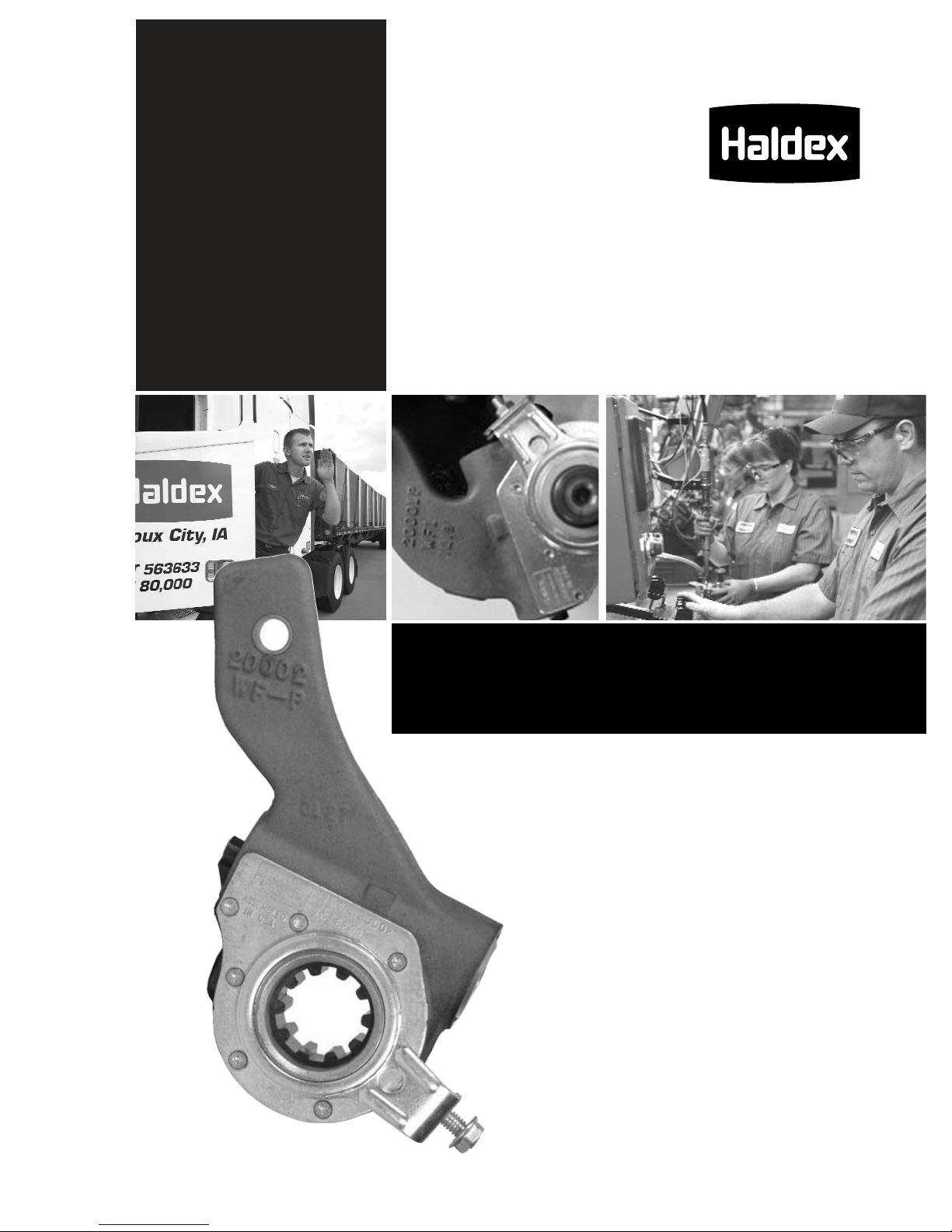
Camshaft Bushings Excessive movement Remove and replace cam bushings per OEM specs
Camshaft Flat spots on cam head Replace camshaft
Cracked/broken splines Replace camshaft
Worn bearing journals Replace camshaft
Chamber Bracket Broken/bent Replace bracket
Clevis Yoke and Pin Worn Remove and replace
Return Springs Broken/stretched or missing Remove and replace springs
Rollers Flat spots, grooved pin/worn Remove and replace roller and pin
Wrong size Remove and replace with correct parts
Spider Anchor Pins Grooved or scored/worn Replace spider or pins per OEM specs
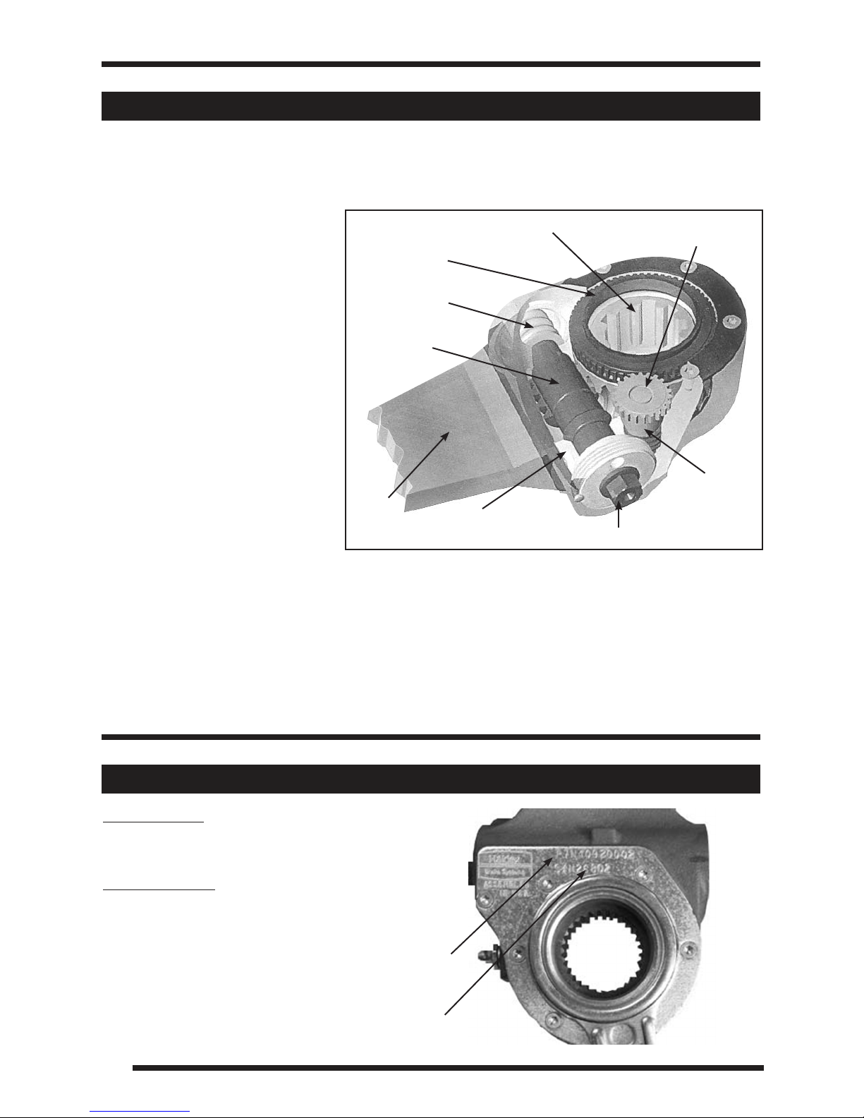
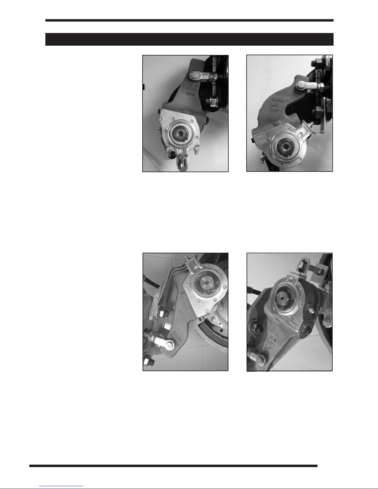
NOTE: Long stroke chambers are identified with
square air ports or port bosses and special trapezoid
ID tags.
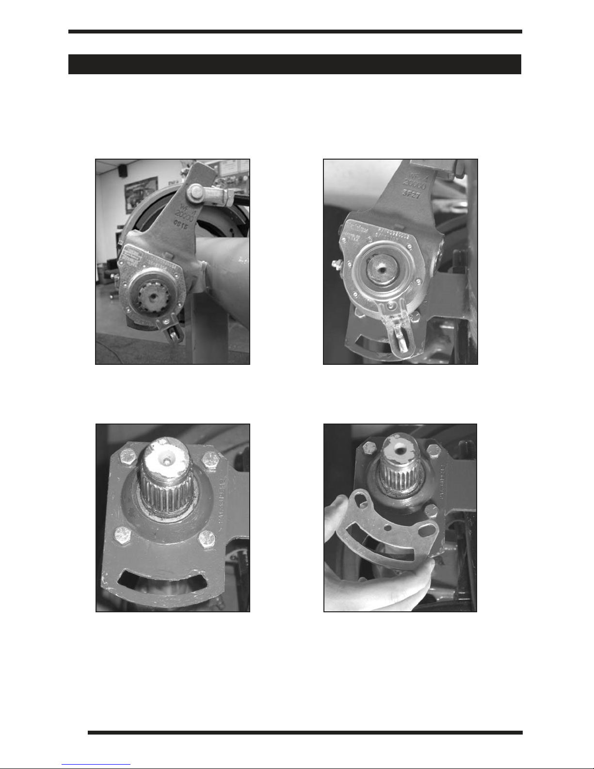
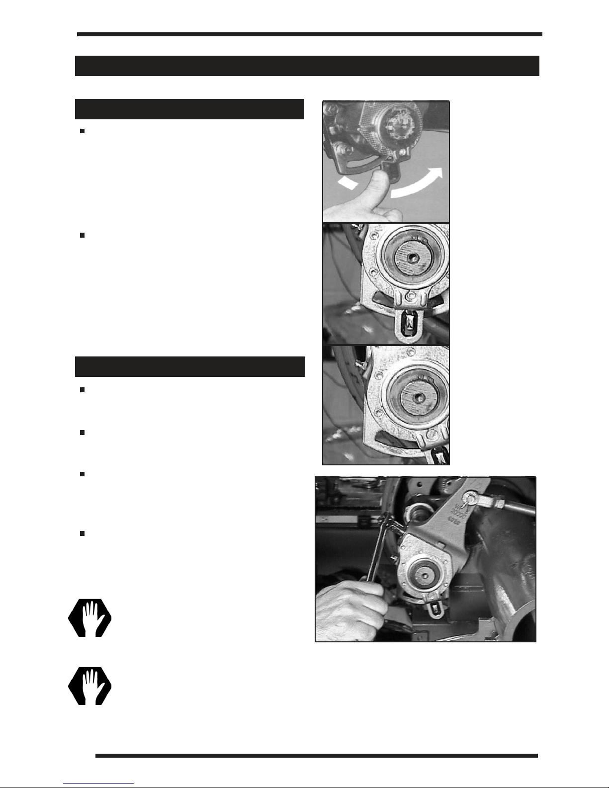
Measuring the Free Stroke
Free stroke is the amount of movement of the adjuster arm required to move the brake shoes
against the drum. With brakes released, measure from the face of the chamber to the center
of the clevis pin “A” (Figure 13). Use a lever to move the brake adjuster until the brake shoes
contact the drum “B” (Figure 13). The difference between the fully retracted and drum contact
measurement “B”–“A” (Figure 13), is the free stroke. The free stroke range should fall between
3/8”–3/4”.
Free Stroke Within The Range
If the free stroke is good, but the applied stroke is too long, there is probably a problem
with the foundation brake. Check the following and reference CVSA out-of-service criteria:
7
Foundation Brake Operational Check/Troubleshooting
Free Stroke
Standard Clamp Type Brake Chamber
Type Adjustment Limit Type Adjustment Limit
9 1-3/8” 24 1-3/4”
12 1-3/8” 30 2”
16 1-3/4” 36 2-1/4”
20 1-3/4”
Long Stroke Type Brake Chamber
Type Adjustment Limit Type Adjustment Limit
16L 2” 24LS 2-1/2”
20L 2” 30LS 2-1/2”
24L 2”
Note: Block wheels to prevent vehicle from rolling.
Ensure system reservoir pressure is at 90-100 psi.
Check that push rod is fully retracted; apply air to release spring brake.
North American Commercial Vehicle Safety Alliance (CVSA) Uniform Vehicle Inspection
Criteria: The applied stroke of the brake should be checked per CVSA guidelines at
90-100 psi reservoir pressure. Applied stroke should be at or less than the specified
readjustment limits as shown below.