PX-2 Installation and Operation Instructions
3. Select Multiple or Single TTL mode by moving the toggle switch on the rear of the light
source. You must also configure this mode in the operating software.
4. Download the latest version of OOIBase32, if necessary.
5. Configure OOIBase32 to operate the PX-2. Access the OOIBase32 setup. In the Configure
A/D dialog box, check the S2000 Strobe Enabled box.
Consult the OOIBase32 documentation for more information on system setup.
If properly configured, the lamp should flash and an audible “ping” sound should be heard.
TTL Mode Information
The PX-2 features a TTL switch that provides two modes of operation: Multiple mode and Single
mode.
Multiple Mode
In Multiple mode, the flash timing (pulse rate) is determined by the spectrometer:
• S2000 Spectrometer – Flash timing is determined by the JP3 jumper block setting. See
• All other OOI spectrometers – The Continuous strobe rate is either fixed or software
controlled. See
In either case, you must alter the spectrometer’s integration time so that a constant number of flashes
are observed during each integration period.
When using Multiple mode, you must ensure that a constant number of flashes occurs for each
integration cycle. This is accomplished by setting the pulse rate and integration time, which is
controlled by OOIBase32 operating software.
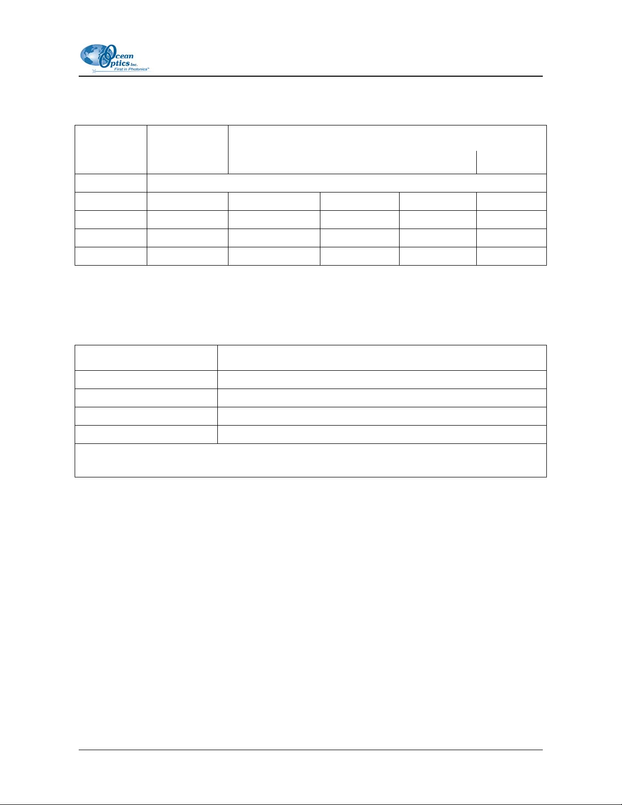
S2000 Spectrometer Strobe Rate Adjustments
To achieve a constant number of flashes per integration cycle, the integration time must be a multiple
of those shown in the following table.
Integration time must be a multiple of (in milliseconds)
S2000 JP3
Setting ADC500/SAD500 ADC1000 DAQ700 ADC2000-PCI
216 (factory
default) 128 64 512 32
214 32 16 128 8
212 8 4 32 2
210 N/A N/A
8
(with a minimum value
of 24 ms)
N/A
4 110-00000-000-01-1005