Contents
Introduction
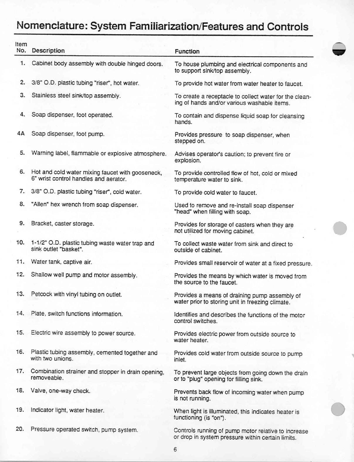
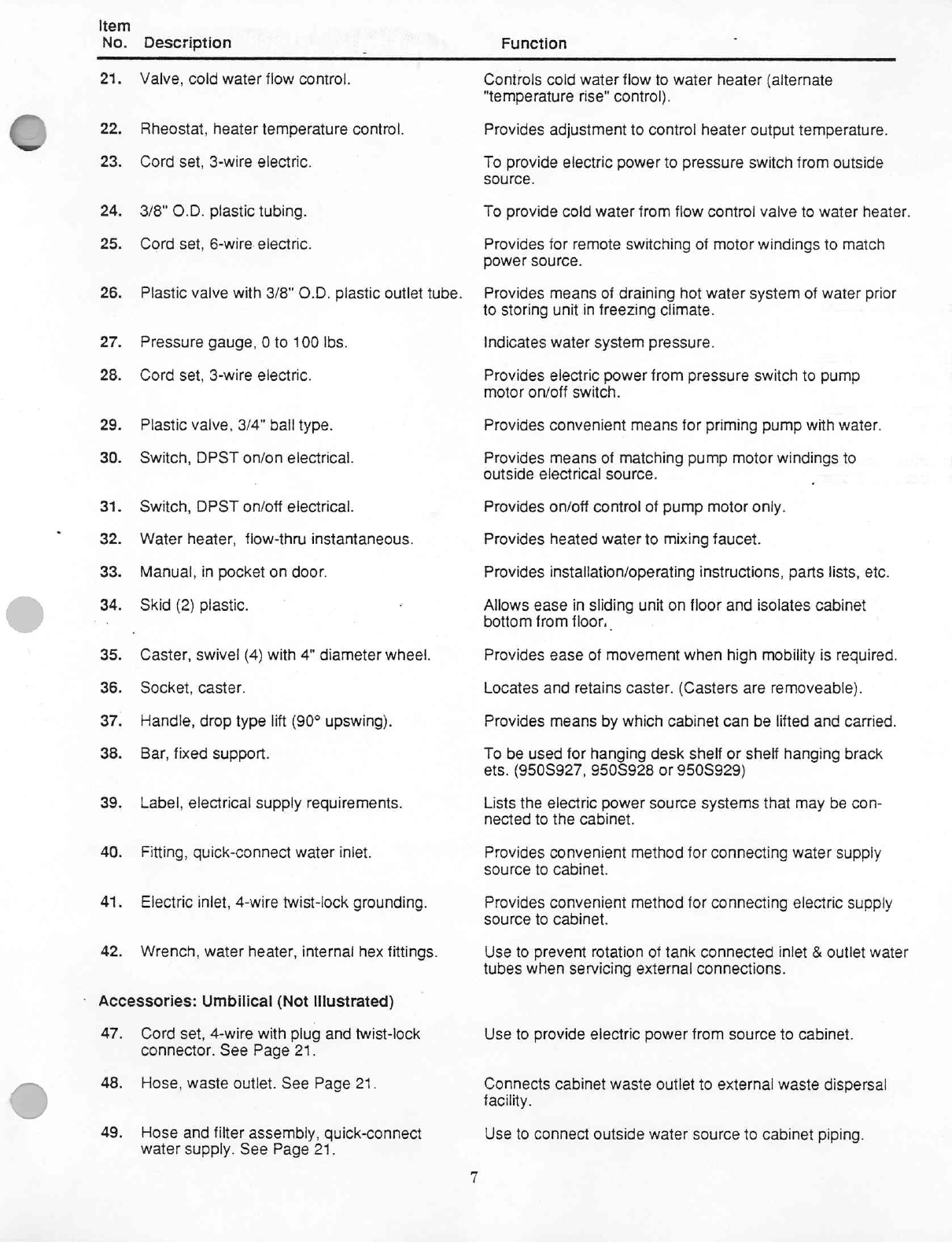
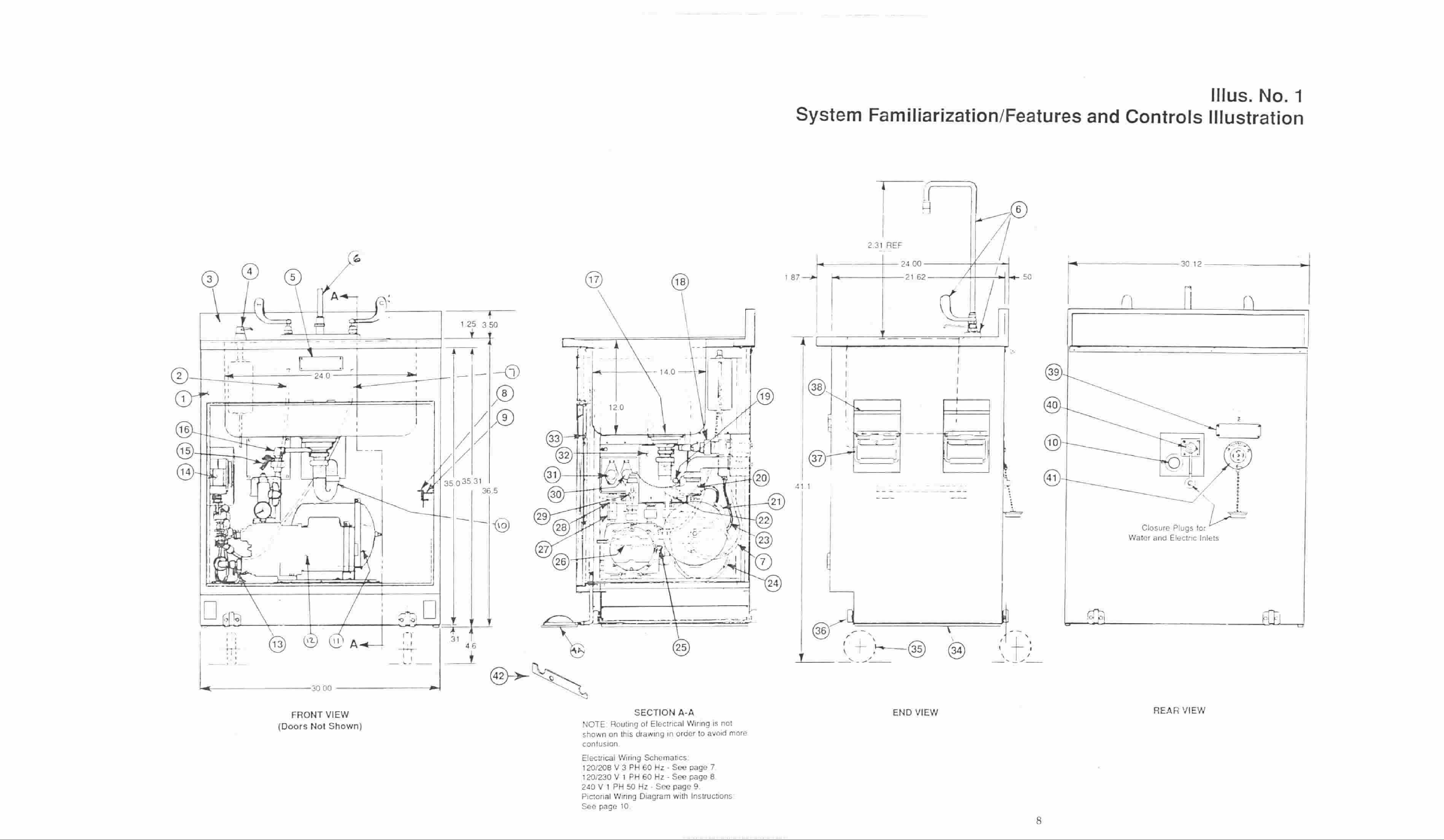
Nomenclature:
System
Familiarization/Features
and
Controls
..............................
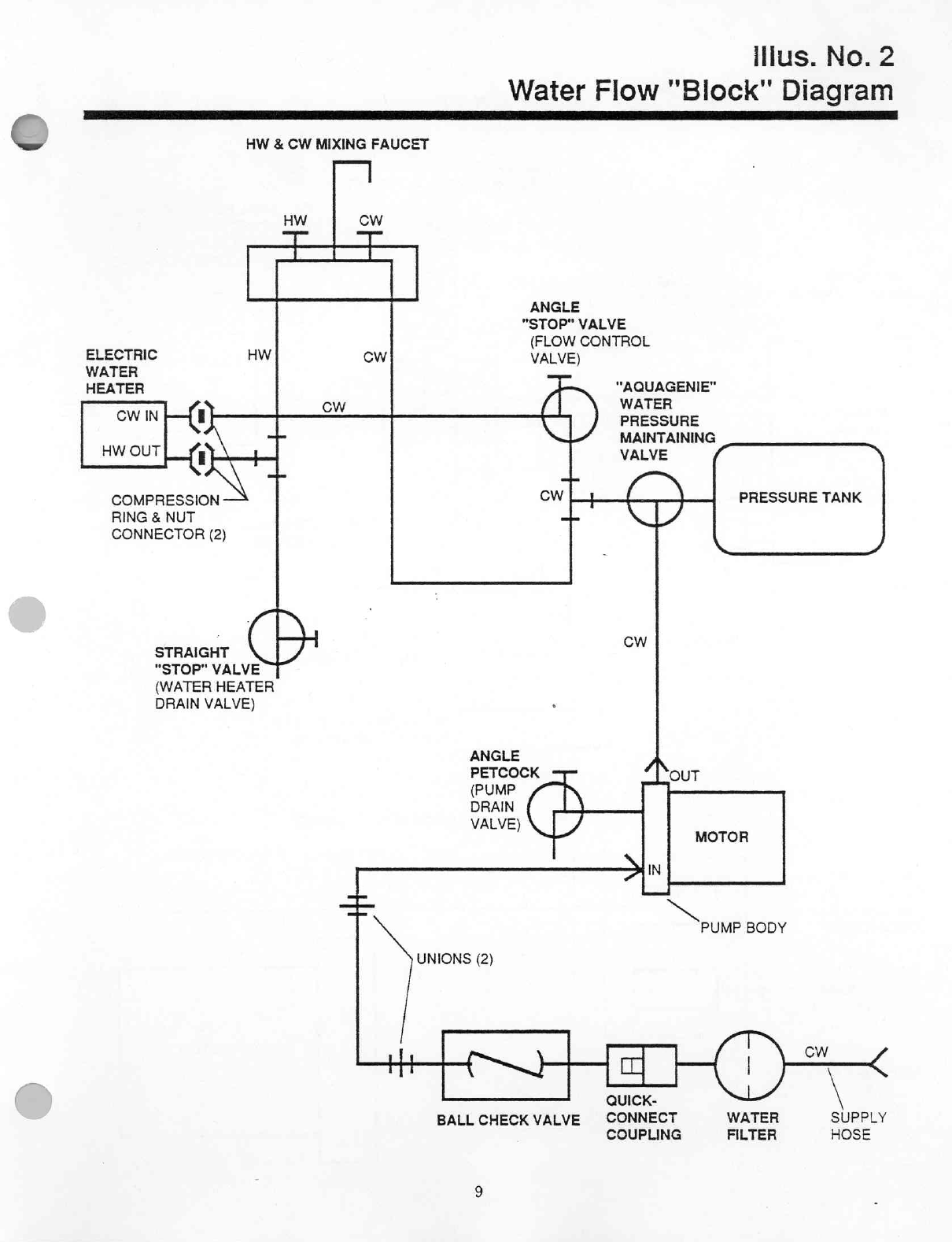
Water
Flow
"Block"
Diagram
............
nen
renerne
rn
rn
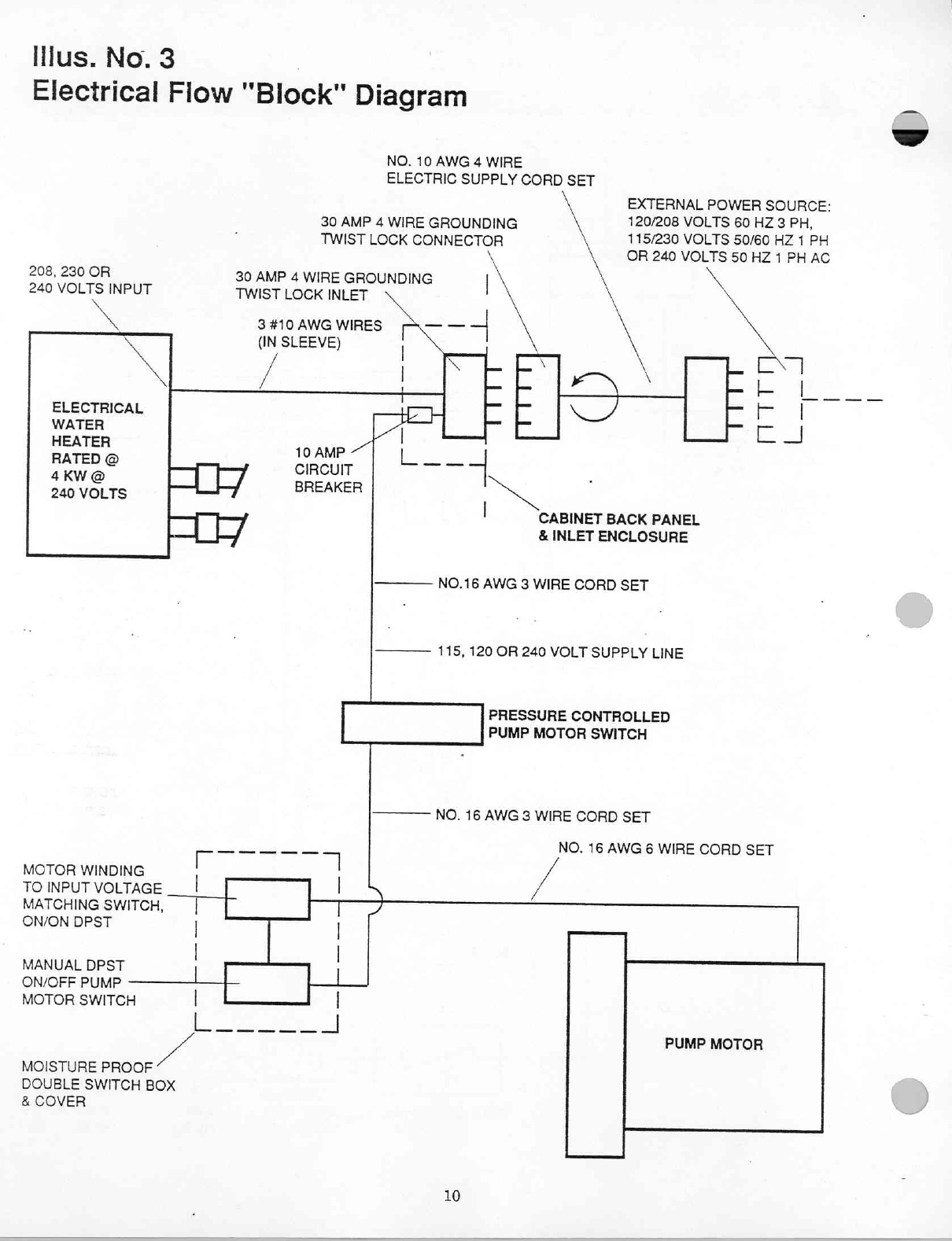
Electrical
Flow
"Block"
Diagram
ee
Patient:
Safety
and'Other
Precautions
mers
Equipment
Care
Installation
and
Operation
Instructions...
линии
seeren
dere
vsere
Electrical
Supply
Requirements
sise
Πο
ο
ο
ο
ο
ο
νο
Water
Drainage
System
and
Preparation
of
Unit
for
Storage
...........................
Storage
Requirements
Electrical
Schematic
-
Sink
Units:
120/208V,
3
Phase,
60
Hz...
120/240V,
1
Phase,
60
月
Ze
240V;
1
Phase.50
ssascsscsccpsczsnssciacitisssssecdsecerenenencnenseenensseraecngenenrsenneenenntenneess
Pictorial
WiringDiagram...........................
een
有
Troubleshooting
-
Super
Power
Pack.......
ra
Componentidentification-WaterHeater.................................................
Replacement
Parts
List
-
Water
Heater
i
ーー
Service
and
Disassembiy
-WaterHeater/Switches.............................................
Electrical
Schematic
-
Water
Heater
Only
oeeeee
eee
ce
Temperature/Flow
Chart
idee
MO
AAA
PümpMaiménance/TrOUDISSROO
NY...
cn
NE
Service
and
Disassembly
-
Pump
Special
Tool
and
ТезЕ
Едшриейи
.....................
линии
иена,
Parts
List
-
Pump
and
Motor
Assembly
ne
ene
eee
ne
nene
Service
and
Adjustments
-
Pressure
Tank
&
Pressure
Switch
................................
Parts'List
=
Sink
Unit
=-30"
Wide
ο
ου
iran
Parts
List
-
Switch,
Heater,
PUMP
ASSEMDIY
.................
ii
Design
Change
Notice
лесопарка
Consumable/Durable
Item
List...
LE
blender
11
12,
13,
14
12
12,
13,
14
14
15
16
17
18
19
20
21
22
23
23
24
25
26
27
27
28
29
30
-
31
32
-
33
34
35