Hamlet STEREO SCOPE 503 EM Service manual

STEREO SCOPE 503 EM
SERIAL DIGITAL/AUDIO MONITOR
OPERATOR'S HANDBOOK
© 2004 Hamlet Video International Ltd. All rights reserved
This handbook contains proprietary information of Hamlet Video International Limited and
may not be copied in whole or in part nor its contents disclosed to any third parties without
the express written consent of the company.
Hamlet Video International Limited
Maple House 11 Corinium Business Centre Raans Road Amersham Bucks HP6 6FB England
Main Line: +44 (0)1494 729 728 Fax Line: +44 (0)1494 723 237 Free phone (UK) 0500 625 525
Hamlet Video International USA service center , Tecads Inc, 23 Del Padre St, Foothill Ranch, CA 92610,
U.S.A. Tel: +1 (949) 597 1053, Fax: +1 (949) 597 1094. Toll Free Tel number: (866) 4 HAMLET
IN CORRESPONDENCE CONCERNING THIS INSTRUMENT
PLEASE QUOTE THE SERIAL NUMBER PRINTED ON THE
LABEL AT THE REAR OF THE UNIT

2

3
CONTENTS
LIST OF FIGURES ............................................................................................................... 4
GENERAL INFORMATION ............................................................................................... 5
WARRANTY ................................................................................................................................................... 5
SAFETY COMPLIANCE ................................................................................................................................ 6
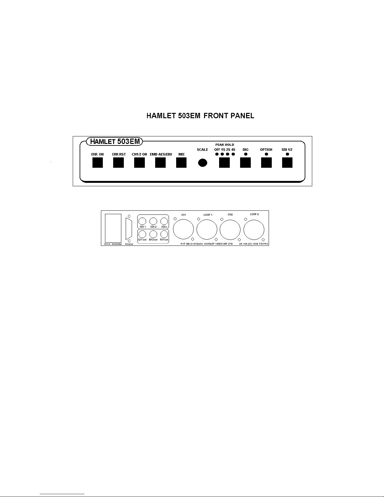
FRONT AND BACK PANELS............................................................................................. 7
INSTALLATION................................................................................................................... 8
UNPACKING .................................................................................................................................................. 8
MOUNTING INSTRUCTIONS....................................................................................................................... 8
POWER REQUIREMENTS ............................................................................................................................ 8
SIGNAL AND CONTROL CONNECTIONS................................................................................................. 8
REMOTE CONTROL...................................................................................................................................... 8
CHECK-OUT FOR INITIAL USE .................................................................................................................. 8
OPERATING INSTRUCTIONS.......................................................................................... 9
OVERVIEW..................................................................................................................................................... 9
CONTROLS................................................................................................................................................... 10
DIGITAL ERROR DISPLAY........................................................................................................................ 11
REMOTE CONTROL.................................................................................................................................... 12
CALIBRATION AND SETTINGS .................................................................................... 14
TECHNICAL SPECIFICATION....................................................................................... 15
SERIAL DIGITAL BASICS............................................................................................... 16
DIGITAL ERROR DETECTION OVERVIEW .............................................................. 17
EMBEDDED AUDIO OVERVIEW .................................................................................. 18
USEFUL WEBSITES .......................................................................................................... 22
CONTACT DETAILS AND CUSTOMER SUPPORT.................................................... 22

4
LIST OF FIGURES
Fig 1 Front View . . . . . . . . . . . . . . . . . . . . . . . . . . . . . . . . . 7
Fig 2 Rear View . . . . . . . . . . . . . . . . . . . . . . . . . . . . . . . . . 7
Fig 3 Serial Digital Basics . . . . . . . . . . . . . . . . . . . . . . . . . . . . . . . . . 19
Fig 4 625 Field Blanking . . . . . . . . . . . . . . . . . . . . . . . . . . . . . . . . . 20
Fig 5 525 Field Blanking . . . . . . . . . . . . . . . . . . . . . . . . . . . . . . . . . 21

5
GENERAL INFORMATION
WARRANTY
This product is manufactured by Hamlet Video International Ltd and is warranted to be free
from defects in components and factory workmanship under normal use and service for a
period of one year from the date of purchase.
FREE EXTENDED WARRANTY
The warranty period can be extended to two years by registering the instrument on the
Hamlet web site
http://www.hamlet.co.uk/serv.html
TERMS AND CONDITIONS
During the warranty period, Hamlet Video International Ltd will undertake to repair or at its
option, replace this product at no charge to its owner when failing to perform as specified,
provided the unit is returned shipping prepaid, to the factory or authorised service facility.
No other warranty is expressed or implied. Warranty shall not be applicable and be void
when this product is subjected to:
1. Repair work or alteration by persons other than those authorised by Hamlet Video
International Ltd in such a manner as to injure the performance, stability, reliability or
safety of this product.
2. Misuse, negligence, accident, act of God, war or civil insurrection.
3. Connection, installation, adjustment or use otherwise than in accordance with the
instructions in this manual.
Hamlet Video International Ltd reserves the right to alter specifications without notice.
This warranty does not affect the statutory rights of the UK customer.

6
GENERAL INFORMATION
SAFETY COMPLIANCE
This product is manufactured and tested to comply with:
BS EN 61010-1 : 1993
Safety requirements for electrical equipment for measurement, control and laboratory use.
EMC COMPLIANCE
We: HAMLET VIDEO INTERNATIONAL LTD
MAPLE HOUSE
11 CORINIUM BUSINESS CENTRE
RAANS ROAD
AMERSHAM
BUCKS
HP6 6FB
ENGLAND
declare under our sole responsibility that the product
HAMLET 503EM
to which this declaration relates are in conformity with the following standards:
EN50081-1
Generic emissions standard for light industrial applications.
EN50082-1
Generic immunity standard for light industrial applications.
following the provisions of EU EMC directives 89/336/EEC and 92/31/EEC.
NOTE. During the EMC certification of this product, shielded cables were used. We
recommend that they be used in operation.

7
FRONT AND BACK PANELS

8
INSTALLATION
UNPACKING
The Hamlet 503EM is shipped to you from the factory in a specially constructed packing
case. Exercise caution when unpacking the device to prevent damage to the case finish.
Examine the unit carefully inside and out for damage which may have occurred during
shipment. Please retain the packing for use in the unlikely event that the unit has to be
returned for repair.
MOUNTING INSTRUCTIONS
The 503EM is designed for desktop operation, or to fit into a standard 19 inch equipment
rack, where it occupies only ½ width and 1U of height. Rack mounting kits are available. The
unit in itself generates little heat and does not need any forced ventilation, but heat generated
from other units should not cause the case temperature to rise above 60 deg.C
POWER REQUIREMENTS
Mains supplies of 110V at 60Hz, 230V at 50Hz or 12V DC are all suitable. The AC voltage
required should be specified when ordering. Due to the use of a switching supply regulator, a
wide variation of +/- 15% in the above levels is acceptable.
SIGNAL AND CONTROL CONNECTIONS
Video input and output cable connections are all made on to 75 ohm BNC. sockets and
AES/EBU audio to 3 pin XLR sockets on the rear panel. To utilise all of the functions of the
unit, the Y, U, V and CST outputs, serial digital input and active loop and AES/EBU audio
input should all be connected.
REMOTE CONTROL
This is available via the rear 9 pin D RS232 socket. Software is available to control the unit
from a virtual instrument panel on any pc.
CHECK-OUT FOR INITIAL USE
After installation as above, apply power to the unit and operate each control in turn, verifying
the response is correct as described in the operating instructions.

9
OPERATING INSTRUCTIONS
OVERVIEW
The Hamlet 503EM is a half rack width, 1U high unit which accepts two channels of CCIR
601 (SMPTE 259M) SDI digital video and converts this to full CCIR quality analogue video,
either YUV or GBR for output to a monitor. There is an additional output, which can be
specified as a composite encoded output or re-clocked SDI input.
The unit can be operated free standing or mounted in a standard 19" rack, on its own or with
another half width unit using optional rack mounting hardware. It operates from 110V or
230V AC mains or 12V dc, using only 10VA of power.
Two coloured audio bar graphs are produced, one on the left side of the screen and the other
on the right. They each display a stereo pair (L and R channels). They display embedded
audio or optionally external AES/EBU digital audio as selected on the front panel.. The
embedded audio group can be selected internally. Audio scales can be set to Digital or
Option, this toggles between BBC type 2 and Nordic for European units and offers VU scales
in USA and Asia pacific.
An in-vision display is produced of the input serial digital parameters. These include CRC
code and errors, signal strength and jitter, missing/illegal codes, gamut errors etc.

10
OPERATING INSTRUCTIONS
CONTROLS
ERR ON
Toggles the digital error display box on and off .
ERR RST
Resets the digital error counters.
CH 1/2 ON
Selects the stereo pair display. Toggles between pair 1 (left of screen), pair 2(right of screen)
and both displays on.
EMB-AES/EBU
Toggles the audio source between audio embedded in the video, external AES/EBU digital
audio and displays off.
MIX
Allows the input video to be seen in the background of the displays. There is an internal
adjustment for transparency level.
SCALE KNOB
Controls the brightness of the internal electronic graticules.
PEAK HOLD
The unit has a peak-hold facility for the audio bars. This button toggles the hold time
between OFF, 1, 2 and 4 seconds.
DIG
Sets the audio scale to the standard PPM digital scale, 0 to -50db. The standard zero level
lineup is -18db on this scale.
OPTION
Toggles the audio scale between BBC type 2 (0 to 7) and Nordic (+12 to -12).
SDI 1/2
Selects SDI inputs 1 or 2. The unselected inputs are always terminated in 75 ohms. The SDI
re-clocked output follows the input selector.

11
OPERATING INSTRUCTIONS
DIGITAL ERROR DISPLAY
ST The signal strength bar is an indication of cable length. It is marked at full and at the
300 metre knee point.
JT The jitter bar shows the data jitter level, often due to re-clocking of a low level or
noisy signal. It is marked at the zero and knee points.
CR Displays the number of CRC (Cyclic Redundancy Check) errors, also known as EDH
(Error Detection and Handling). The errors can be selected to cover the full field
including auxiliary data packets or more usually active picture area only. There is an
internal switch for this. The counter counts from 0 to 99 errors and may be reset at
any time by pressing the front panel ERR RST button.
To the right of the CR display are 4 digits representing the checksum of the last
frame, full frame or active picture as selected. For a stationary test card, this will be
a fixed number and is a useful diagnostic aid when the CRC/EDH word of the test
card is known. For moving pictures, the checksum will change with every frame.
Note: CRC/EDH depends on a data packet being sent by the originating equipment. If
the signal source does not support CRC/EDH, ---- is displayed in the CRC area.
CD Displays the number of code errors. These are due to missing or corrupted TRS
pulses (EAV or SAV). The counter operates as above.
DA Displays the number of digital audio errors. The signal source can be either
embedded audio or AES/EBU input, selected by an internal switch. If embedded
audio is chosen and no embedded audio packets are present, -- is displayed. The
counter operates as above.
GM Displays the number of gamut errors. These occur if the digital luminance signal
exceeds peak white or falls below minimum black. Also if the digital colour signals
exceed peak positive or negative. The counter operates as above.
IL Displays the number of illegal value errors. Illegal values are 3FF and 000. The
counter operates as above.
The number of quantising bits in the data system is also detected and shown in the
error display area as 8 or 10.

12
OPERATING INSTRUCTIONS
REMOTE CONTROL
FOR MORE DETAILED INFORMATION, PLEASE READ THE DISC HELP FILE.
The software package is for remote control of the Hamlet 503EM from a personal computer
via an RS 232 serial link. It is recommended that the disk be copied to your hard disk drive
and then kept safely as a backup. Please note this version is for a Microsoft Windows™
Environment. Microsoft Windows 95™ and DOS versions are available from the factory if
required. Before installation of the application please ensure that your system is able to run it
correctly.
HARDWARE REQUIRED
IBM PC or 100% compatible personal computer with at least 1M Byte of RAM.
A VGA type colour monitor.
A Hard Disk Drive.
An RS-232 Serial Port for connection to the 503EM.
A Mouse.
A 3.5" Floppy Disk Drive .
SOFTWARE REQUIRED
MS DOS™ Version 3.3 or greater with Microsoft Windows™ Version 3.0 or greater.
Hamlet Video 503EM software (disk supplied).
The software consists of the following files:
503EM.EXE Executable file
VBRUN300.DLL Runtime file
503EM.HLP HELP file. This is a text file which maybe printed out or called from
the HELP window while running the application.
503EM.SET Setup file of 4 bytes.
INSTALL.EXE Installs the software on your hard disk.
INSTALLATION FROM DOS:
To install the software on your hard disk first ensure the computer is in DOS, fit the
application disk in the floppy drive,
Type A: to give the A:> prompt then type INSTALL <enter>
This will create a directory on your hard disk called C:\HAMLET then the application files
will be copied to that directory. Note: The files are not protected or compressed so they may
be manually copied to any directory required.
The INSTALL program also sets up the serial port

13
OPERATING INSTRUCTIONS
TO RUN THE SOFTWARE FROM WINDOWS™
On first use of the software, a group window and application file are needed.
To Create a Group Window, start Windows in the usual manner, e.g. Type WIN <enter>
From the Program Manager Window select: FILE NEW. Select Program Group
In the description box type: HAMLET. Select OK
To Add the Application file, in the Group Window, select FILE NEW, select Program Item
In the Description box type 503EM
In the Command box type the full path name of the application:
i.e. C:\HAMLET\503EM.EXE Select OK.
The software is now installed on your hard disk and can be called from the Windows
Program Manager in the normal way. i.e. double click on the HAMLET Group icon, then
double click on the AUDIO icon. The first time the software is run it may be necessary to set
the COM PORT option in the SETTINGS window. Remember to save it before you return to
the main panel window.
OPERATION
From the Hamlet Program Manager, double click on the 503EM icon.
BUTTONS
Use the mouse to point and click the required buttons.
VARIABLE CONTROLS
These use arrows on the computer panel and can be operated in 2 ways.
1) Point the mouse at the arrow of a slider control and hold down the left mouse button,
this causes the control to increment or decrement slowly.
2) Point the mouse at the arrow of a slider control and double-click the left mouse
button, this causes the preset function to operate.
THE OPTIONS MENU.
BEEP ON/OFF.
When each control is pressed the computer issues a beep, this may be disabled if not required
by clicking the "beep off" button.
THE HELP WINDOW Click on HELP for the information text, which can be scrolled with
the mouse on the "vertical scroll bar" on the right of the window or from the keyboard cursor
or the PgUp and PgDn keys.
TO QUIT THE PROGRAM Double click on the "control menu box" (top left window
button)

14
CALIBRATION AND SETTINGS
CALIBRATION
Isolate the mains supply before removing the top cover!
YUV output levels
With 100% colour bars, adjust R14 for 700mV video and R81 for 300mV sync.
Adjust R15 (U) and R16 (V) for 700mV pp outputs.
Adjust R59 for green audio bar Y level of 411mV.
Select MIX and adjust R61,R65 and R66 for desired mix levels.
For composite subcarrier lock, set C69 (PAL) and C68 (NTSC) for 1.5V on R118.
SETTINGS
PL6 selects YUV or RGB outputs.
JP4 selects 'syncs on green' output.
Other jumpers are used for initial testing purposes and should not be changed.
SW1- (1) The CRC/EDH can be set to full field (ON) or active picture (OFF)
SW1- (2&3) EMBEDDED AUDIO GROUP 2 3
1 ON ON
2 OFF ON
3 ON OFF
4 OFF OFF
SW1- (4) Not used.

15
TECHNICAL SPECIFICATION
DISPLAY
The audio bar graphs are burnt into the decoded video signal.
Channels 1 and 2 are displayed on the left side.
Channels 3 and 4 are displayed on the right side.
Embedded audio groups 1 to 4 are selected by an internal switch.
SIGNAL CONNECTIONS
Audio 3 pin XLR female socket and passive loop per AES/EBU channel.
Balanced input, impedance 470 ohms.
SDI in 75 ohm BNC socket.
Loop Re-clocked active loop output. 75 ohm BNC socket.
Out YUV/RGB and composite outputs to monitor, 1 Volt to 75 ohms.
DIGITAL DECODER
Input: SMPTE 259M, ITU-R BT.601/656 serial component. 800mV pp +/-
10% auto equalised to 300 metres.
Output Y,U,V, +/-1db to 5.5MHz. Oversampling digital filter for CCIR 601
compatibility.
AUDIO CHARACTERISTICS
Digital 0 to -50db scale with PPM characteristics.
Option Toggles between BS5428 type 2a meter (1 to 7) and
Nordic type 1 meter (+12 to -12)
POWER REQUIREMENTS
AC: 105V-120V A.C. at 48Hz to 66Hz @ 8VA, with 100ma slow T fuse.
AC: 210V-250V A.C. at 48Hz to 66Hz @ 8VA, with 100ma slow T fuse.
DC: 7V-14V D.C.@ 0.4 amps.
ENVIRONMENT
Indoor use, 5 to 45 deg.C. ambient to 2,000m.
Max humidity 80% to 31 deg.C decreasing to 50% at 40 deg.C.
Overvoltage category 2. Pollution degree 1.
WEIGHT
1.85Kg.

16
SERIAL DIGITAL BASICS
625 and 525 digital component video is produced by applying a 4:2:2 sampling structure to
the analog signal. This process is defined by a sub-set of international standards ITU-R
BT.601 and BT.656. (these were formerly known as CCIR-601 and CCIR-656. The label
'CCIR601' is commonly applied to digital video coded in this manner.)
The luminance (Y) component is sampled at 13.5 MHz, and the colour difference
components (U and V) are both sampled at 6.75 MHz. With 10 bit quantisation, this results in
a data stream of 10 bit words at a clock frequency of 27 MHz. If the signal source uses 8 bit
quantisation, 10 bit data is used with the two least significant bits of each sample code set to
binary zero. This is to maintain the same data rate.
The quantizing levels employed in the analog to digital conversion are set to give 66.4mV
headroom above peak white and 51.1mV below black. Coded U and V signals have 50mV
above and below their normal maximum and minimum excursions.
The synchronisation pulses are discarded in the coding process, and are replaced by Timing
Reference Signals (TRS), which are inserted into the data stream to serve the same purpose.
Two TRS's are used to synchronise the data stream, EAV (End of Active Video) and SAV
(Start of Active Video). These are placed at the beginning and end of the horizontal video
blanking period. See fig 3.
Each TRS consists of 4 words:
1) 3ff hex i.e. all '1's
2) 000 hex i.e. all '0's
3) 000 hex i.e. all '0's
4) XYZ, which determines the type of TRS pulse:
XYZ:
Bit 9: always '1'
Bit 8: 0 = frame 1 1 = frame 2
Bit 7: 0 = normal 1 = field blanking
Bit 6: 0 = SAV 1 = EAV
Bit 5: Bits used for Hamming correction.
Bit 4: Bits used for Hamming correction.
Bit 3: Bits used for Hamming correction.
Bit 2: Bits used for Hamming correction.
Bit 1: Always '0'
Bit 0: Always '0'

17
SERIAL DIGITAL BASICS
The period between EAV and SAV is not used by normal video and is available for other
purposes e.g.: error checking, timecodes or embedded audio.
Illegal Values: The values 0 and 3FF hex are used solely by TRS pulses (EAV and SAV) they
must not appear anywhere in the active video area.
Out of Gamut: Values apart from the illegal values, which should not be used.
Luminance is defined as being between peak white, 700mV 3AC, hex and
black, 0mV 040 hex.
Chroma is defined as being between max positive, 350mV 3C0, hex and
max negative, -350mV 040 hex.
The values above and below these are termed out of gamut.
The data is serialised using an NRZ (None Return to Zero) code to produce a 270 Mb/s
signal. This coding method removes any low frequency component and is insensitive to
polarity. The data has to be scrambled first to avoid the possible transmission of all '0's.
This data is output at 800mV p-p to normal 75 ohm video coaxial cable.
Due to the high frequencies, the cable losses are quite high, typically 10dB per 100 metres at
270 MHz. To allow acceptable cable lengths, automatic cable equalises are used at the
receiver, which usually allow up to 300 metres of cable to be used. It is important that
standard cable is used, otherwise the equaliser will not compensate correctly.
Suitable cable is: PSF 2/3 BELDEN 8281 F&G 1.0/6.6
DIGITAL ERROR DETECTION OVERVIEW
In order to check if the digital video signal has been received correctly a Cyclic Redundancy
Check (CRC) can be made on each frame in the generating equipment, this four digit number
is then placed in a 'packet' and put in the EAV-SAV space of one line of each field.
At the receiving equipment the incoming video field also has a Cyclic Redundancy Check
number calculated, this value is then compared with the 4 digit number sent in the packet. If
the two numbers are not identical an error has occurred between transmission and reception
of the signal.

18
SERIAL DIGITAL BASICS
This type of error detection is known as Error Detection and Handling or EDH and is defined
by SMPTE RP165. In practice two check sums are sent per frame, one for the active video
period and one for the full frame. A typical packet consists of:
The Header: (000, 3FF, 3FF) This always precedes an EDH packet.
Data ID: (1F4)
Block Number: (200)
Data Count: This contains the number of words that follow.
Active picture crc: 3 words
Full-field crc 3 words
Error flags: 3 words
Reserved: 7 words
Check Sum: This is used to test for transmission errors.
EMBEDDED AUDIO OVERVIEW
The period between the EAV and SAV markers can be used to send embedded digital audio
signals. This is known as SMPTE 272M. Up to 16 separate audio signals may be sent in a
single video channel. These are organised as four GROUPS of four signals, the four signals
are often two stereo pairs. Typically only one group will be used, giving two stereo pairs of
audio. The audio data is digitised in the sending equipment to 20 bits of resolution, usually at
a 48 KHz sample rate. Often only 16 bits are used in practice. The digitised data is arranged
in packets which are placed in the EAV-SAV space.
A typical packet consists of:
The Header: (000, 3FF, 3FF) This always precedes an audio packet.
Data ID: This contains the Audio Group number.
Block Number: AES blocks have 192 'frames' of audio data
Data Count: This contains the number of words that follow.
Audio Sample:
Audio Sample:
Audio Sample:
Audio Sample:
Check Sum: This is used to test for transmission errors.
Each audio sample consists of a sample of all four audio signals,
e.g.: Channel 1 left, Channel 1 right, Channel 2 left, Channel 2 right.
Each signal requires 3 words to hold all 20 bits data, thus each audio sample has 12 words in
it. Typically 3 or 4 audio samples are sent in each EAV-SAV period.
As with the video signal, words which consist of all '1's or all '0's are not allowed.

19
SERIAL DIGITAL BASICS
Fig 3.

20
SERIAL DIGITAL BASICS
SD SDI Field Blanking – 625
Fig 4 .
This manual suits for next models
1
Table of contents
Popular Speakers System manuals by other brands

Teufel
Teufel cinebar 11 Technical description and user manual

JVC
JVC CA-MXJD8UW instructions

Panasonic
Panasonic SCHDX3 - AMPLIFIER SPEAKER SYSTEM operating instructions

Bose
Bose 301 Series III Service manual

Bose
Bose LIFESTYLE RoomMate owner's guide

Klipsch
Klipsch Audiorock Owner's manual and installation instructions