Hammond Organ A-100 Series User manual

THEORY OF OPERATION
SERIES A-100
Figure 1
These Models of The Hammond Organ ontain the entire tone-produ ing me hanism, whi h is
ompletely ele tri al in operation. Within it are produ ed all the tones and tone ombinations of the
organ. The ele tri al waves are made audible by suitable amplifiers and loud speakers, ontained
within the onsole. The blo k diagram (Figure 7) shows the hief omponents of the instrument.
Ele tri al impulses of various frequen ies are produ ed within a unit known as the "tone generator",
ontaining a number of "phoni wheels" or "tone wheels" driven at predetermined speeds by a
syn hronous motor and gear arrangement. Ea h phoni wheel is similar to a gear, with high and low
spots, or teeth, on its edge. As the wheel rotates these teeth pass near a permanent magnet, and the
resulting variations in the magneti field indu e a voltage in a oil wound on the magnet. This small
voltage, when suitably filtered, produ es one note of the musi al s ale, its pit h or frequen y depending
on the number of teeth passing the magnet ea h se ond.
A note of the organ, played on either manual or the pedal keyboard, generally onsists of a fundamental
pit h and a number of harmoni s, or multiples of the fundamental frequen y. The fundamental and eight
harmoni s available on ea h playing key are individually ontrollable by means of drawbars and preset
keys. By suitable adjustment of these ontrols the player is enabled to vary the tone olors at will.
The resulting signal passes through the expression or volume ontrol and through the preamplifier
(where vibrato is introdu ed) to the power amplifier and the self- ontained speakers.
Reverberation is added ele tri ally by a se ond amplifier whi h drives a reverberation speaker, also
lo ated in the onsole
1 tuttotastiere.com

DESCRIPTION
Ea h Hammond Organ onsole (Fig. 1) in ludes two manuals or keyboards: the lower, or Great, and
the upper, or Swell; and a pedal keyboard of 25 keys. The operation of the ontrols of this model is
overed in the following paragraphs.
STARTING THE ORGAN
To start the organ, hold the "start" swit h (Fig. 2) in "on"
position for approximately eight se onds. Still holding it,
push the "run" swit h on "on" position. After leaving both
swit hes on for about four se onds, release the start
swit h to return to its normal position.
If the onsole is very old, or if a frequen y regulater is
used, it may be ne essary to hold the start swit h slightly
longer. A pilot light shows when the organ is turned on.
PRESET KEYS
At the left end of ea h manual are twelve keys identi al to the playing keys ex ept reversed in
olor (Fig.3).
When a preset key is depressed it lo ks down and is released only when another is depressed.
The ex eption to this is the an el key at the extreme left, whi h serves only to release any key
whi h may be lo ked down. Only one preset key is used at one time. If by mistake two are
depressed and lo ked, they may be released by means of the an el key.
Ea h preset key, with the ex eption of the an el key and
the two "adjust" keys at the extreme right of the group,
makes available a different tone olor whi h has been set
up on the preset panel lo ated inside the onsole. These
tone olors are set up at the fa tory in a ordan e with a
standard design whi h :as been found to best meet the
average organist's reqirements. They may be hanged, if
desired, by removing the ba k of the onsole and
hanging the preset panel onne tions in a ordan e with
instru tions on a ard lo ated near the preset panel.When
either "adjust" key is depressed, the organ speaks with
whatever tone olor is set up on the harmoni drawbars
asso iated with that key. The per ussion effe t an be
used only, when the upper manual 'B' preset key is
depressed (see "per ussion" also)
2 tuttotastiere.com

HARMONIC DRAWBARS
Ea h onsole has four sets of harmoni drawbars, two for ea h manual. Figure 4 shows one group of
harmoni drawbars, by whi h the organist is enabled to mix the fundamental and any, or all, of eight
different harmoni s in various proportions. The third bar from the left ontrols the fundamental, and
ea h of the other bars is asso iated with a separate harmoni . If a drawbar is set all the way in, the
harmoni it represents is not present in the mixture.
Ea h drawbar may be set in eight different positions by the organist in addition to the silent position.
Ea h position, as marked on the drawbars, represents a different degree of intensity of the harmoni it
ontrols. When drawn out to position 1, the harmoni it represents will be present with minimum
intensity; when drawn out to position 2, with greater intensity; and so on up to position 8.
A tone olor is logged by noting the numeri al position of the various drawbars, For instan e, the tone
set up on Figure 4 is known as tone 34 630 5210. After a tone is so logged it may be made available
again by setting the harmoni drawbars to that number.
HARMONIC DRAWBARS FOR THE PEDALS
In the pedals the harmoni resour es have been ombined into two drawbars whi h may be used
separately or in ombination. When the left drawbar is used, emphasis is given to the lower
harmoni s, and similarly the higher harmoni s are emphasized when the right drawbar is used.
The pedal drawbars are lo ated between the two sets of manual drawbars.
NORMAL - SOFT VOLUME CONTROL
This ontrol (Fig. 3) is a tilting tablet whi h supplements the a tion of the expression pedal. In "soft"
position it redu es the volume of the whole instrument. It is parti ularly useful when playing in a
small room or when the organist wishes to pra ti e without disturbing others
EXPRESSION OR SWELL PEDAL
The swell pedal, lo ated in the ustomary position, is operated by the right foot, and with it the
volume of the organ may be ontrolled over a wide range. It operates on the two manuals and
pedals equally; that is to say, on e the manuals and pedals are balan ed, they retain their relative
balan e over the entire swell pedal range
3 tuttotastiere.com

VIBRATO
The vibrato effe t is reated by a periodi
raising and lowering of pit h, and thus is
fundamentally different from a tremolo, or
loudness variation. It is omparable to the
effe t produ ed when a violinist moves his
finger ba k and forth on a string while
playing, varying the frequen y while
maintaining onstant volume.
The vibrato me hanism in ludes an ele tri al
time delay line, whi h shifts the phase of all
tones fed into it. A rotating s anner, mounted
on the main tone generator, pi ks up
su essive signals from various line se tions.
These signals represent various amounts of
phase shift, and the ombination of signals
produ es a ontinuous frequen y variation.
Figure
These Models have the "sele tive vibrato" feature whi h makes the vibrato effe t available on
either manual separately or on both together. Two tilting tablets ontrol the vibrato for the two
manuals, while the rotary swit h (Figure 5) sele ts the degree of vibrato or vibrato horus effe t.
The "Great" tablet ontrols the vibrato for the pedals as well as for the Great manual.
PERCUSSION
The "Tou h-Response Per ussion" feature is ontrolled by four tilting tablets (Fig. 6) at the upper
right side of the manuals. Per ussion is available only on the upper manual and only when the 'B'
preset key is depressed. The four tablets (from left to right) sele t Per ussion on or off, normal or
soft Volume, fast or slow De ay, and se ond or third Harmoni tone quality.
Per ussion tones are produ ed by borrowing the se ond or third harmoni signal from the
orresponding manual drawbar, amplifying it, returning part of the signal to the same drawbar, and
ondu ting the balan e of the signal through push-pull ontrol tubes where its de ay
hara teristi s are ontrolled.
The Per ussion signal is then ombined with the
signal from the manuals and pedals after the vibrato
ir uit but ahead of the expression ontrol. The
ontrol tubes are keyed by the eighth harmoni key
onta ts and busbar.
4 tuttotastiere.com

TONE GENERATOR
The main tone generator furnishes 91 different musi al frequen ies. It in ludes a tone wheel,
magnet, and oil for ea h frequen y. Mounted on top of the generator are tuned filters to insure
purity of the tones.
PREAMPLIFIER
The Preamplifier is lo ated within the onsole, suspended from the main generator shelf. Its
purpose is to amplify the signals before sending them to the amplifier. This unit also houses the
ele tri al portion of the swell or expression ontrol .
POWER AMPLIFIER
A twelve watt amplifier is mounted on the lower shelf of the onsole. It re eives the signal from the
Preamplifier and in reases it in power to drive the two 12" speakers.
REVERBERATION SYSTEM
To the left of the amplifier are the reverberation amplifier and reverberation unit. A portion of the
output signal of the power amplifier passes through the reverberation unit to the reverberation
amplifier and this drives a third 12" speaker housed within the onsole. The degree of
reverberation heard an be regulated by rotating the knob marked "Reverberation Control" shown
in Figure 5.
In operation, an ele tri al signal from the amplifier is applied to the driver unit in the reverberation
devi e whi h then onverts the ele tri al signal into me hani al energy. This energy is transmitted
through springs to a pi kup unit where a part of it is onverted ba k to ele tri al energy. The
remaining portion is refle ted ba k to the driver and again ba k to the pi kup at a time interval
determined by the spring lengths. This transa tion ontinues until the signal energy is redu ed to
one millionth of its original value. The transfer time from driver to pi kup and the refle tions within
the system itself produ e the reverberation effe t.
USE OF TONE CABINETS
Any Hammond Tone Cabinet may be atta hed to these organs by use of the proper able plugged
into the outlet to the right of the AC input plug. Reverberation from the onsole is not transferable
to these Tone Cabinets. further information on onne tion of multiple tone abinet installation, refer
to Se tion 4 of Servi e Manual overing larger models.
ECHO CONTROL
If a tone abinet as mentioned above, is added, an e ho ontrol an also be atta hed. This permits
use of the self ontained speaker or the added tone abinet independently. One position of the
ontrol permits both to play simultaneously. Complete instru tions for its installation a ompanies
the kit
5 tuttotastiere.com

INSTALLATION AND MAINTENANCE
The organ must be onne ted to a regulated-frequen y sour e of the voltage and frequen y
spe ified on the name plate. If the frequen y is not regulated, the pit h of the organ will be
irregular.
When a onsole is set up for operation, the an horing must be loosened so that the generator will
float freely on its spring suspension system. No damage will result if this is not done, but the
onsole will sound noisy, and the same is true if the an horing is loosened but the onsole is not
level. If the onsole is to be moved a long distan e the an horing should be tightened during su h
moves.
Instru tions for loosening and tightening the generator in the onsole are given on the instru tion
ard ontained in the ben h.
The tone generator is lubri ated by putting oil into ups inside the onsole. Add oil in a ordan e
with the instru tion within the onsole.
When pla ement of onsole has been ompleted after loosening of generator, as des ribed above,
the reverberation unit if ne kla e type should be unlo ked by moving its lever "up". The unit should
be again lo ked whenever the onsole is moved, even if only a few feet. Consoles, serial number
above 6127 do not require any lo king or unlo king operation.
To repla e the pilot lamp, remove the ba k over, if the onsole has one. It is a pin type lamp, 6.3
volts, #12.
6 tuttotastiere.com

TECHNICAL SECTION
THE HAMMOND TONE GENERATOR
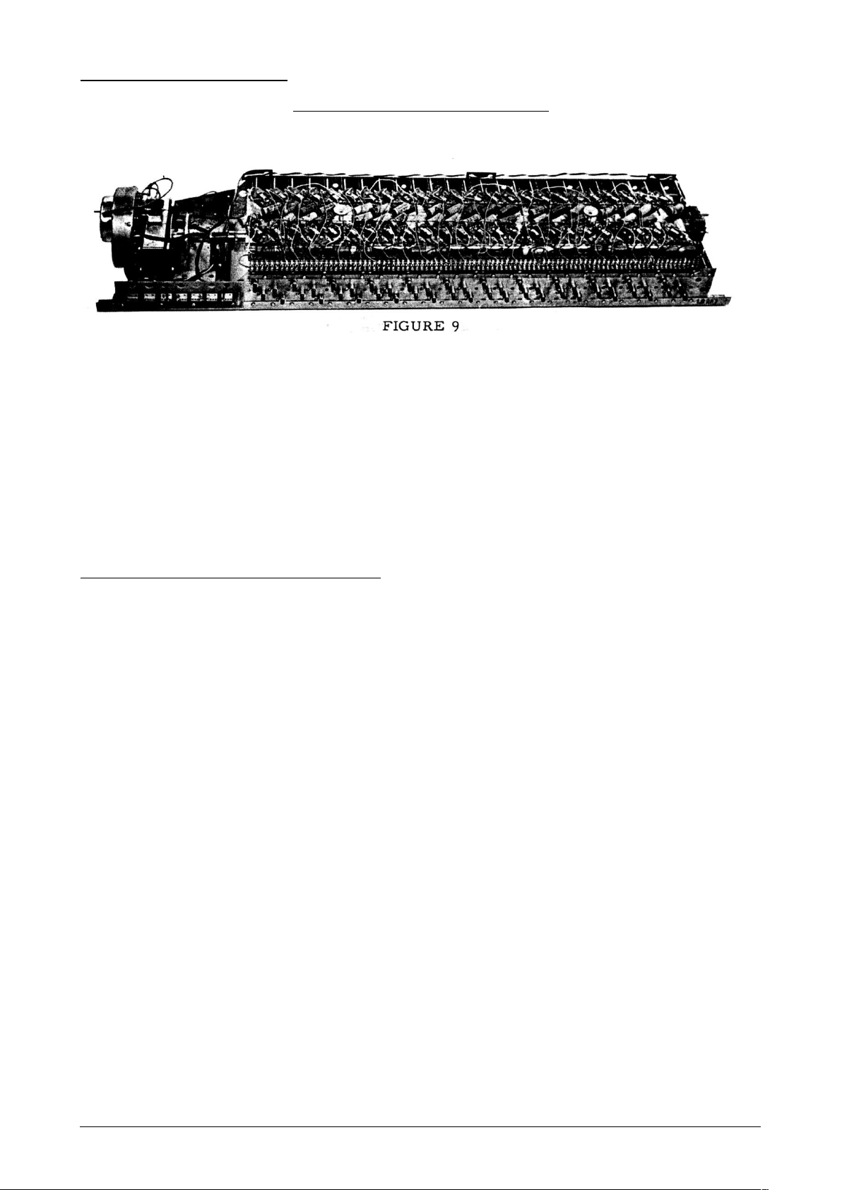
The A-100, A-101 and A-102 embodies the Hammond ele tro-me hani al tone generator
as its sour e of tone. A pi ture of this generator is shown below.
The generator assembly in ludes a shaded-pole indu tion motor for starting, a non-self-starting
syn hronous motor for driving the unit after it is started, and a Vibrato S anner mounted on the
syn hronous motor. The entire assembly is mounted on two long steel angles whi h also provide
the means of mounting the tone generator in the onsole. The method of mounting is su h as to
minimize the transmission of vibration from the tone generator to the onsole.
A drive shaft, resiliently oupled to the syn hronous running motor, extends the entire length of the
generator. Twenty-four driving gears, two ea h of twelve sizes, are mounted on this shaft, and the
drive shaft itself is divided into several se tions onne ted by flexible ouplings. The starting motor
is mounted at the end of this drive shaft, opposite to the syn hronous motor.
STARTING AND SYNCHRONOUS MOTORS
As mentioned above, a shaded-pole indu tion motor is used for starting the generator and is
lo ated at the right end of the generator as viewed from the ba k. The rotor of this motor will slide
endwise when urrent is supplied and engage a pinion on its shaft with a gear on the generator
driving shaft.
When the organ is started, the starting swit h is turned on and held for about 8 se onds while the
starting motor brings the system up to slightly greater than syn hronous speed. The "run"swit h is
then turned on. This swit h simultaneously onne ts the syn hronous motor and introdu es a
resistor in series with the starting motor thus redu ing its driving power. With a braking a tion of the
syn hronous motor and a loss of power of the starting motor, the system slows to syn hronous
speed and the syn hronous motor begins to arry the load. A period of about 4 se onds should be
allowed for this to take pla e, after whi h the starting swit h may be released. The starting swit h
springs ba k to the "off" position, and turns off the starting motor, whi h is then disengaged from
the rotating shaft by a spring.
It should be noted that the syn hronous motor an supply power only at syn hronous speed.
Therefore, if for any reason the system fails to rea h syn hronous speed it will not ontinue to run
after the starting swit h is released. Failure to start properly is usually due to in reased oil vis osity
or low line voltage and may sometimes be over ome by a in rease in starting time.
As the s hemati diagram indi ates, the "run" swit h in its "off" position shorts out the wirewound
resistor atta hed to the line panel. If the "run" swit h is defe tive in its "off" position, the generator
will not start be ause this resistor will be permanently in series with the starting motor. Before
assuming that there is anything amiss with the motors, short out this resistor and start the
generator in the normal manner. If the generator operates satisfa torily, repla e the "run" swit h.
7 tuttotastiere.com

THE TONE WHEELS
The main generator is a long stru ture in whi h are mounted 48 rotating assemblies, ea h
onsisting of a shaft and two dis s known as tone or phoni wheels. These assemblies are oupled
resiliently to the drive shaft. Ea h of the driving gears engages two bakelite gears asso iated with
rotating assemblies on opposite sides (See Figure 11).
These bakelite gears rotate freely on the shafts with the tone wheels, and are oupled to their
respe tive assemblies by a pair of oil springs. There are 12 sizes of bakelite gears, orresponding
to the 12 sizes of driving gears. Thus 4 of the tone wheel assemlies, ea h with 2 tone wheels, run
at ea h of 12 speeds.
Ea h tone wheel is a steel dis about 2 in hes in diameter, a urately ma hined with a definite
number of high and low points on its edge (See Figure 10).
Ea h high point on a tone wheel is alled a tooth. The number of teeth on ea h of these tone or
phoni wheels, in onjun tion with the speed at whi h the tone wheel is revolving, determines the
frequen y of the tone generated.
Ea h driving gear, with its two bakelite gears and four tone wheels, runs in a separate
ompartment magneti ally shielded from the rest by steel plates whi h divide the generator into a
series of bins.
All four tone wheels in any one ompartment run at the same speed. The individual tone wheel
shafts are mounted in bearings made of a spe ial porous bronze and ea h of these bearings is
onne ted to the oiling system by a otton thread from the oil trough. Thus, oil from the trough is
arried by apillary a tion to all bearings, penetrating them and lubri ating the a tual bearing
surfa e. The drive shaft and both motors are lubri ated in a similar manner. It is very important to
use the re ommended grade of oil, as it is essential to the proper operation of the organ that the
generator be well lubri ated. If oil of other grades is used, it is likely the the generator may be
sluggish in starting, and in time the threads may gum up and prevent the proper flow of oil. Follow
oiling instru tions within the onsole.
8 tuttotastiere.com

The two spring ouplings on the motor shaft, the flexible ouplings between se tions of the drive shaft,
and the tone wheel spring ouplings all ontribute to absorbing variations in motor speed. The
syn hronous motor does not deliver absolutely steady power, but rather operates with a series of
pulsations, one with ea h half y le. If the tone wheels were rigidly oupled to the motor, this slight
irregularity would arry extra frequen ies into ea h tone wheel. In addition, "hunting" is suppressed by
the resilient ouplings and inertia members of the syn hronous motor proper.
Asso iated with ea h tone wheel is a magnetized rod about 1/4 of an in h in diameter and 4 in hes in
length, with a oil of wire wound near one end (See Figure 10).
The tip of the magnet at the oil end is ground to a sharp edge and mounted near the edge of the tone
wheel. Ea h time a tooth passes this rod it auses a hange in the magneti field, whi h indu es a
small voltage in the oil, the frequen y being determined by the number of teeth and the wheel speed.
Small oils are used on the higher frequen y magnets and larger oils on the lower frequen ies. It is
found that large pole pie es are needed on the low frequen y magnets to give proper output, but it is
ne essary to use smaller ones on the high frequen ies to prevent ex essive iron losses.
Some of the oils have opper rings mounted on them for the purpose of redu ing harmoni s. As these
are used only on fairly low frequen y oils, the eddy urrent loss in su h a ring is small for the
fundamental frequen y of that oil, but high for its harmoni s. This has the effe t of redu ing the relative
intensities of any harmoni s whi h may be produ ed by irregularites in the tone wheels. The wheels are
ut so to give as nearly a sine wave as possible, but the generated voltage seldom rea hes that ideal
ondition, sin e even a slight hange in the air gap will hange the wave form.
9 tuttotastiere.com

The tip of ea h magnet, as well as the edge of ea h tone wheel, is oated with la quer to prevent
orrosion, for, should oxidation set in, the hange in tooth shape would introdu e irregular
frequen ies.
Lo ations of the various magnet and oil assemblies are shown in Figure 12.
They are identified by their frequen y numbers, and the broken line between any two numbers
indi ates that these two frequen ies are supplied by one tone wheel assembly.
Ea h magnet gap is set at the fa tory with the set s rew partially loosened, while observing an
output meter. Experien e has shown that the magnets seldom need adjustment and that setting
them without proper equipment involves danger of damaging both magnet and wheel. Therefore it
is not re ommended that the servi e man attempt this adjustment.
GENERATOR FILTERS
As a means of eliminating any vagrant harmoni s that may be present, there are filters onsisting
of small transformers and ondensers asso iated with ertain frequen ies. The transformers have
a single tapped winding, and this tap is grounded, so one side, whi h is onne ted to the
orresponding magnet oil through a ondenser, forms a resonant ir uit for the fundamental
frequen y of that oil. This tends to emphasize the fundamental and suppress harmoni s.
Lo ations of these transformers are shown in Figure 13.
They are also shown in the s hemati .
10 tuttotastiere.com

These transformers and ondensers are mounted on the top of the generator assembly. The
transformers are mounted at an angle, thus minimizing interferen e between them. The ores of
the transformers are made of a spe ial iron, and the number of laminations used is adjusted to
se ure the proper indu tan e.Wires from the magnet oils onne t to the transformers, and wires
from the transformers lead to the terminal strip on the generator.
This terminal strip arries the output frequen ies of the generator, whi h are arbitrarily numbered
from 1 to 91 in order of in reasing frequen y. This frequen y numbering is ontinued throughout
the instrument. The frequen ies are not in order on the terminal strip, and Figure 13 indi ates the
arrangement. Several terminals at the right end are grounded to the generator frame and serve to
ground the manuals and pedals.
Transformers and ondensers are not used below frequen y 44, but a length of resistan e wire
shunts ea h generator. Frequen ies 44 to 48 have transformers only, while both transformers and
ondensers are used for frequen ies 49 to 91.
Two ondenser values are used - 0.255 mfd for frequen ies 49 to 54, and 0.105 mfd for
frequen ies 55 to 91. The transformers are all different. Ea h transformer is mat hed to its
ondenser and any repla ements are supplied as mat hed pairs by the fa tory.
11 tuttotastiere.com

THE MANUAL CHASSIS ASSEMBLY
The manual hassis assembly, Fig. 14, in ludes the upper and lower manuals and the
preset panel. It has a terminal strip under ea h manual to a ommodate the ne essary
frequen y wires from the tone generator assembly. Ea h manual has 61 playing keys, 9
preset keys, and 2 adjust keys, ea h of whi h operates nine small bronze onta t springs
with pre ious metal points (See Figure 15). When a key is pressed these points make
onta t with nine busbars extending the entire length of the manual. The busbars also
have pre ious metal onta t surfa es.
The nine onta t springs under ea h key arry the nine harmoni s of the parti ular note
with whi h they are asso iated (See Figure 16) and are onne ted by resistan e wires to
the proper terminals on the terminal strip. Therefore all key onta ts are alive whenever
the generator is running.
12 tuttotastiere.com

ARRANGEMENT OF MANUAL CONTACTS
When a playing key is pressed, its nine frequen ies are impressed on the nine busbars of the manual.
As there are no wires onne ted to these busbars, a preset or adjust key must be depressed before
any ir uit an be ompleted. Ea h preset and adjust key has nine onta ts exa tly like those of the
playing keys. These keys have a lo king and trip me hanism whi h lo ks down one key at a time.The
key at the extreme left end of the manual is a an el key, with no onta ts, whi h releases any preset
or adjust key that happens to be depressed.
The adjust keys, A# and B, are onne ted by flexible wires, olor- oded for easy identifi ation, to the
orresponding nine drawbars. The drawbars slide over nine busses whi h are onne ted to taps on the
mat hing transformer. These orrespond to different intensities of sound as shown by numbers on the
drawbars.
The two left groups of drawbars are asso iated with the upper manual, while the two right groups work
in onjun tion with the lower manual. In ea h ase the A# adjust key ontrols the left hand group of
drawbars for that manual.
The nine preset keys, from C# to A in lusive, are wired to flexible leads terminating at the preset panel
in the ba k of the onsole, where the various tone olors are set up by onne ting ea h wire to a s rew
terminal orresponding to the desired intensity of the harmoni . These s rew terminals are lo ated on 9
horizontal bars, ea h representing a ertain intensity for all wires atta hed to that bar.
The drawbar busses and the preset panel bars are onne ted in parallel to taps on the primary of the
mat hing transformer.
13 tuttotastiere.com

Manual Busbar Shifters
The pre ious metal onta t surfa es of the key onta ts and busbars are not subje t to
orrosion, and the manuals are sealed to ex lude dust as far as possible. In spite of these
pre autions an o ational parti le of dust may lodge on a onta t and ause the note to be
s rat hy, noisy, or silent, and for this reason a busbar shifting me hanism is provided on
ea h manual to slide the busbars endwise and thus provide a fresh onta t surfa e. The
busbar shifter for ea h manual is a slotted stud near the right end of the manual as viewed
from the ba k of the onsole (see rear view of onsole, Figure 8, for lo ation) .
If any note be omes s rat hy or silent, the key should first be stru k 15 or 20 times in a
rapid sta ato manner to loosen the dirt. This will usually dislodge the parti les and lear
the note.
In ase this pro edure is not effe tive, the busbar shifter for that manual may be adjusted
by turning the stud about two turns in either dire tion. It may sometimes be ne essary to
hold down the offending key while turning the busbar shifter, in order to wipe the onta t
lean.
14 tuttotastiere.com

Manual Wiring
Figure 19, a wiring hart for the playing manuals, will be helpful in tra ing diffi ulties
asso iated with the generator or manuals. Both manuals are wired alike.
Preset Panel
The tone signals from the preset keys are arried by olor- oded wires to the divided
preset panel in the ba k of the onsole.
Ea h preset wire, arrying a single harmoni , is fastened under a s rew on the bar whi h
represents the desired intensity of that harmoni . This is equivalent to setting a harmoni
drawbar to the orresponding number. One part of the preset panel is used for the swell
(upper) manual and the other for the great (lower) manual and pedals.
When shipped, ea h organ has its presets set up as shown in the playing instru tions
furnished with the organ. Preset ombinations may be hanged at will by removing the
onsole ba k and following the dire tions on a ard inside. This ard is reprodu ed below.
(Figure 17).
OPERATION OF MECHANISM ON PRESET KEYS
In their basi onstru tion the preset keys are identi al to the playing keys. Ea h has a
plasti key mounted on a metal hannel, pivoted in the rear and with a guide toward the
front to minimize side motion.
On the front edge of ea h hannel of the 9 preset keys and 2 adjust keys, two flat springs
are atta hed, one 5/8" long of rather stiff material, and another approximately 3/4" long of
softer material. The softer long spring is sandwi hed on top of the stiff spring, nearest to
the key. The an el key has only one heavy spring approximately 1" long.
When a preset key is depressed, the longer soft spring is for ed downward and snaps
under a tubular rod whi h is part of the radle. The radle is onstru ted of two tubes
approximately 6" long and assembled 3/4" apart. One tube is used as a ful rum, the entire
assembly being mounted perpendi ular to the preset keys, A spring and bumper hold the
radle at a 60 degree angle toward the front of the onsole.
15 tuttotastiere.com

On e a key has been depressed, the soft spring remains under the tube. It is ba ked by
the short stiff spring to give it suffi ient tension to hold the key down. When the next preset
key is depressed, the radle is for ed down and outward, permitting the previously
operated key to ome up, but again lo king the one last depressed.
If two preset keys are depressed at on e, both will lo k down. The an el key with its long
stiff spring is then used and for es the radle down, ausing all preset keys depressed to
return to their normal position. As there is no lo king spring on the an el key, it will
immediately return to its normal position.
Repla ement of Preset "Cradle" Return Spring
If it is determined that a new return spring is ne essary on either manual, remove the
onsole top and musi ra k and take the bolts holding the manual assembly out from the
bottom of the onsole. Raise the upper manual, or both manuals, as ne essary, to gain
a ess to the s rews holding the left hand end blo k of the manual needing the
repla ement. After removal of the end blo k, the end of the radle assembly, as well as the
broken return spring and its bra ket, will be visible.
Remove the bra ket and broken spring and dis ard. Repla e, using Part No. AO-21709-0.
Install the new assembly so that the felt pad is above the preset radle, and the flat spring
is below the radle, as shown in Figure 18. Clamp it in the enter of the range of
adjustment provided by the slot. Che k all preset keys for operation, and adjust the
position of the new assembly in ase any keys do not operate orre tly.
16 tuttotastiere.com

Key Number Note Drawbar 1 Drawbar 2 Drawbar 3 Drawbar 4 Drawbar 5 Drawbar 6 Drawbar 7 Drawbar 8 Drawbar 9
1 C 13 20 13 25 32 37 41 44 49
2 C# 14 21 14 26 33 38 42 45 50
3 D 15 22 15 27 34 39 43 46 51
4 D# 16 23 16 28 35 40 44 47 52
5 E 17 24 17 29 36 41 45 48 53
6 F 18 25 18 30 37 42 46 49 54
7 F# 19 26 19 31 38 43 47 50 55
8 G 20 27 20 32 39 44 48 51 56
9 G# 21 28 21 33 40 45 49 52 57
10 A 22 29 22 34 41 46 50 53 58
11 A# 23 30 23 35 42 47 51 54 59
12 B 24 31 24 36 43 48 52 55 60
13 C 13 32 25 37 44 49 53 56 61
14 C# 14 33 26 38 45 50 54 57 62
15 D 15 34 27 39 46 51 55 58 63
16 D# 16 35 28 40 47 52 56 59 64
17 E 17 36 29 41 48 53 57 60 65
18 F 18 37 30 42 49 54 58 61 66
19 F# 19 38 31 43 50 55 59 62 67
20 G 20 39 32 44 51 56 60 63 68
21 G# 21 40 33 45 52 57 61 64 69
22 A 22 41 34 46 53 58 62 65 70
23 A# 23 42 35 47 54 59 63 66 71
24 B 24 43 36 48 55 60 64 67 72
25 C 25 44 37 49 56 61 65 68 73
26 C# 26 45 38 50 57 62 66 69 74
27 D 27 46 39 51 58 63 67 70 75
28 D# 28 47 40 52 59 64 68 71 76
29 E 29 48 41 53 60 65 69 72 77
30 F 30 49 42 54 61 66 70 73 78
31 F# 31 50 43 55 62 67 71 74 79
32 G 32 51 44 56 63 68 72 75 80
33 G# 33 52 45 57 64 69 73 76 81
34 A 34 53 46 58 65 70 74 77 82
35 A# 35 54 47 59 66 71 75 78 83
36 B 36 55 48 60 67 72 76 79 84
37 C 37 56 49 61 68 73 77 80 85
38 C# 38 57 50 62 69 74 78 81 86
39 D 39 58 51 63 70 75 79 82 87
40 D# 40 59 52 64 71 76 80 83 88
41 E 41 60 53 65 72 77 81 84 89
42 F 42 61 54 66 73 78 82 85 90
43 F# 43 62 55 67 74 79 83 86 91
44 G 44 63 56 68 75 80 84 87 80
45 G# 45 64 57 69 76 81 85 88 81
46 A 46 65 58 70 77 82 86 89 82
47 A# 47 66 59 71 78 83 87 90 83
48 B 48 67 60 72 79 84 88 91 84
49 C 49 68 61 73 80 85 89 80 85
50 C# 50 69 62 74 81 86 90 81 86
51 D 51 70 63 75 82 87 91 82 87
52 D# 52 71 64 76 83 88 80 83 88
53 E 53 72 65 77 84 89 81 84 89
54 F 54 73 66 78 85 90 82 85 90
55 F# 55 74 67 79 86 91 83 86 91
56 G 56 75 68 80 87 80 84 87 80
57 G# 57 76 69 81 88 81 85 88 81
58 A 58 77 70 82 89 82 86 89 82
59 A# 59 78 71 83 90 83 87 90 83
60 B 60 79 72 84 91 84 88 91 84
61 C 61 80 73 85 80 85 89 80 85
Frequen y Number
Figure 19
17 tuttotastiere.com

PEDAL SWITCH ASSEMBLY
The pedal swit h (shown in Figure 20) is similar in internal onstru tion to the manuals ex ept that only four
busbars are in luded instead of nine (Figure 21). Ea h of the 25 pedals a tuates a double set of onta t
springs, making eight onta ts available for ea h note. Ea h note onsists of a fundamental and a number of
harmoni s, no sub-harmoni s being used. The pedal onta t springs are onne ted to terminals by
resistan e wires similar to those used in the manual assembly, and a able onne ts these terminals to the
proper terminals on the generator terminal strip.
Four olored wires arry the pedal tones from the busbars to the pedal drawbars. The wires are onne ted
first to a resistor panel on the ba k of the manual assembly. A small hoke oil and resistor mounted on the
manual assembly are wired to the lower drawbar (see Figure 22) and serve to filter out any higher harmoni s
or transients whi h might be present in the lower pedal frequen ies.
18 tuttotastiere.com

Figure 23 is a wiring hart for the pedals,showing the frequen y numbers appearing on
ea h pedal onta t.
Pedal #. Note Fund 2nd Harm
/3rd Harm
2nd
Harm 4th Harm 6th Harm 8th Harm 10th
Harm
12th
Harm
1 C 1 13 13 25 32 37 41 44
2 C# 2 14 14 26 33 38 42 45
3 D 3 15 15 27 34 39 43 46
4 D# 4 16 16 28 35 40 44 47
5 E 5 17 17 29 36 41 45 48
6 F 6 18 18 30 37 42 46 49
7 F# 7 19 19 31 38 43 47 50
8 G 8 NC 20 32 39 44 48 51
9 G# 9 NC 21 33 40 45 49 52
10 A 10 NC 22 34 41 46 50 53
11 A# 11 NC 23 35 42 47 51 54
12 B 12 NC 24 36 43 48 52 55
13 C 13 32 25 37 44 49 53 56
14 C# 14 33 26 38 45 50 54 57
15 D 15 34 27 39 46 51 55 58
16 D# 16 35 28 40 47 52 56 59
17 E 17 36 29 41 48 53 57 60
18 F 18 37 30 42 49 54 58 61
19 F# 19 38 31 43 50 55 59 62
20 G 20 39 32 44 51 56 60 63
21 G# 21 40 33 45 52 57 61 64
22 A 22 41 34 46 53 58 62 65
23 A# 23 42 35 47 54 59 63 66
24 B 24 43 36 48 55 60 64 67
25 C 25 44 37 49 56 61 65 68
Frequen y Number
Frequen ies used in pedal swit h (Figure 23)
19 tuttotastiere.com

Pedal Swit h Busbar Shifters
The pedal swit h is equipped with busbar shifters similar to those on the manuals. The
pedal busbar shifter is a Slotted stud on the near surfa e of the pedal swit h, near the left
end as you look in at the ba k. It should be adjusted as des ribed under "Manual Busbar
Shifters" on a previous page.
Pedal Keyboard
Pedal keys are set at the fa tory for average tension, but are adjustable to fit the
requirements of the individual organist. Adjustment is a omplished by removal of the top
over at the ba k of the pedal keyboard and setting the tension as desired.
20 tuttotastiere.com
Table of contents
Other Hammond Organ Musical Instrument manuals