Hammond Organ L-100 Series User manual


INTRODUCTION TO REVISED MANUAL
Welcome to the revised edition of the Hammond L–100 Series
Service Manual.
Started in late 2018, this edition updates the original manual for
the modern era. Changes include:
• Schematics recreated in Illustrator allowing support for
interactive comparisons between models and a 17MB
reduction in le size
• Spelling and typographic mistakes corrected
• Hyper-links added to cross-references, table of contents,
gures, etc.
• Images touched up
• Most images added in-line with column text to aid on-screen
viewing
• Page layout redesigned for a compromise between
landscape printing and on-screen reading
• Font changed to sans serif (Helvetica Neue) for easier on-
screen readability
I–1 METHOD
The original service manual had been scanned by an unknown
source. This was then downloaded and OCR-ed.
OCR errors were either corrected or re-keyed. Then all text was
composited in Adobe InDesign. Images were captured, edited,
and enhanced in Adobe Photoshop.
I–2 REVISION HISTORY
The following revisions have been made:
Revision Date Comments
Original ca. 1961 Original service manual written by
Hammond Organ Company
1.0 November, 2018 Initial update by Michael
Hightower
1.1 February, 2022 Added Kon Zissis’ modications,
minor edits
To suggest corrections/improvements or to add content, please
contact Michael Hightower via mphtower@gmail.com.
I–3 PRINTING INSTRUCTIONS
The main body of the document is typeset on 8.5” x 11” (US
Letter) in a landscape format. The schematics are typeset on 8.5”
x 14” (US Legal) in a landscape format.
Pages numbers and layout:
• 8.5” x 11 (US Letter) Landscape:
Cover page – 37
55 — End of document
• 8.5” x 14 (US Legal) Landscape:
39 — 54

Page iii
Table of Contents
1. How the Organ Operates ...........................7
1-1. General....................................7
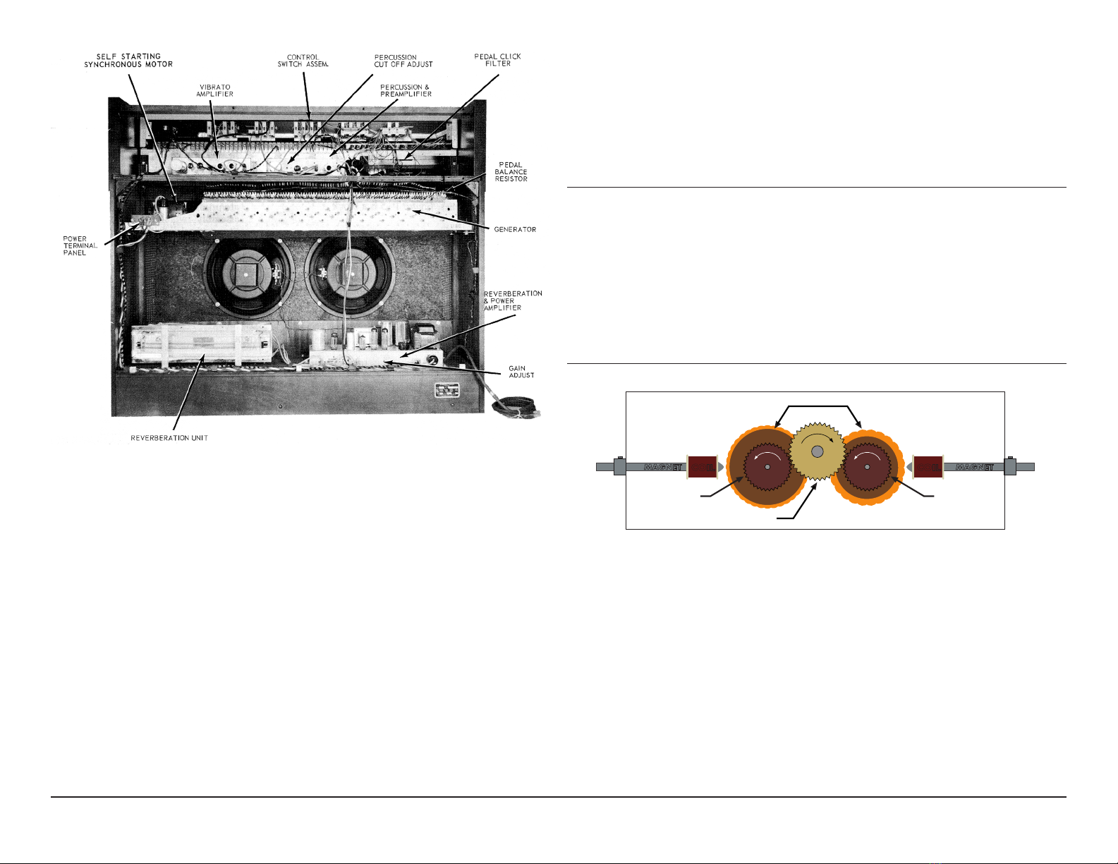
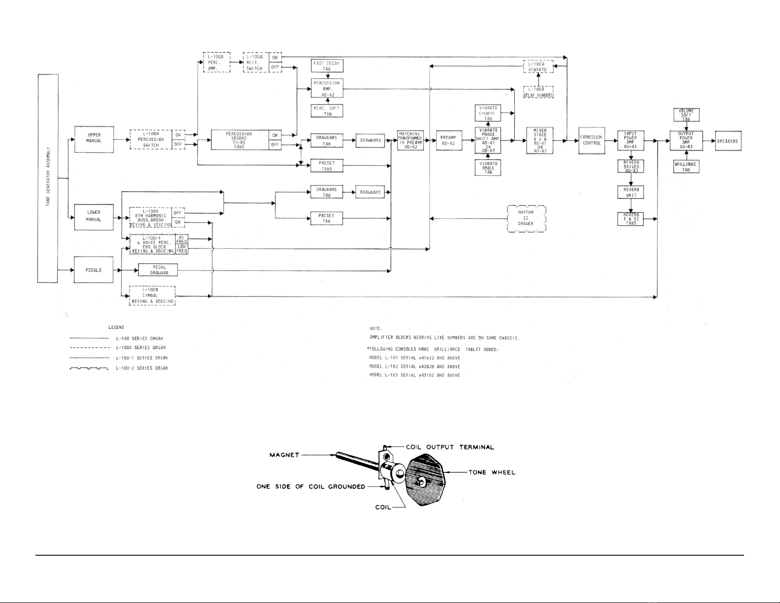
1-2. Tone Source ................................7
1-3. Motor and Power Switch ......................8
1-4. Tone Generator..............................8
1-5. Manuals ..................................11
1-6. Harmonic Drawbars .........................13
1-7. Pedal Drawbar .............................13
1-8. Pedal Keyboard ............................13
1-9. Expression Pedal ...........................14
1-10. Control Tabs ...............................14
1-11. Preset Tabs ...............................14
1-12. Vibrato Tabs ...............................14
1-13. Reverberation And Volume Soft Tabs ...........14
1-14. Percussion Control Tabs .....................14
1-15. L–100A Preset Percussion Unit ................14
1-16. L–100–1 Six-Voice Percussion Feature...........15
1-17. External Equipment .........................16
1-18. Extension Speakers .........................16
1-19. External Sound Source ......................16
1-20. Earphones ................................16
2. Theory of Operation ..............................17
2-1. General...................................17
2-2. Pre-Ampliers..............................17
2-3. Vibrato Phase Shift Amplier ..................17
2-4. Percussion Amplier. . . . . . . . . . . . . . . . . . . . . . . . . 18
2-5. Reverberation and Power Amplier .............19
2-6. Power Supply ..............................19
2-7. L–100A Percussion Voicing Circuitry ............19
2-8. L–100–1 Six-Voice Percussion Circuitry ..........21
3. Disassembly ....................................24
3-1. General...................................24
3-2. Access ...................................24
3-3. Upper Manual Key ..........................24
3-4. Lower Manual Key ..........................24
3-5. Drawbar Contact Spring. . . . . . . . . . . . . . . . . . . . . . 24
3-6. Drawbar, Drawbar Knobs or Drawbar Assembly ...25
3 -7. Upper Manual..............................25
3-8. Lower Manual..............................26
3-9. Generator .................................26
3-10. Motor ....................................26
3-11. Pedal Keyboard ............................26
3-12. Swell Assembly ............................27
3-13. To Replace a Broken Tab .....................27
3-14. Pilot Light or Power Switch ...................27
3-15. Percussion Circuitry, L–100A ..................28
3-16. Six-Voice Percussion Circuitry, L–100–1..........28
4. Practical Service Suggestions......................29
4-1. General...................................29
4-2. Organ Performance Check ...................29
4-3. Equipment Required.........................29
4-4. Procedure ................................29
4-5. Vibrato ...................................30
4-6. L–100A Percussion Performance Check .........32
4 -7. L–100–1 Six-Voice Percussion Performance Check
And Troubleshooting ..............................34
5. Diagrams ......................................37
5-1. General...................................37
5-2. Interactive Schematic Instructions ..............37
6. L-Series Parts List ...............................55
6-1. Overview .................................55
6-2. Changes from Source Document...............55
6-3. Assembly List ..............................56
6-4. Parts List .................................58
7. Modifications ...................................81
7-1. Overview .................................81
7-2. Connecting a Leslie or Other External Speaker ....81

Page v
INTRODUCTION TO ORIGINAL SERVICE MANUAL
II–1 OVERVIEW
This manual contains service information for L–100 Series organs.
The series is comprised of the following models:
L–100
L–100A
L–100–1
L–100–2
L–200
The Model L–100 Hammond organ is a completely self-contained
console, requiring no external tone cabinet. It has two manuals
or keyboards of 44 keys each, a 13 note pedal keyboard, and an
expression (swell) pedal for controlling the volume. All tones are
produced by electro-magnetic tone generators and electrically
amplied. Selection of tone colors is made by adjusting 17
drawbars and 6 preset tabs. Other characteristics of the music are
adjusted by means of 10 other tabs. A toggle switch, located to
the right of the console above the manuals, is used to turn on the
organ. A pilot light shows when the organ is turned on.
Model L–100A is similar to Model L–100, with the addition of
percussion voicing circuitry, controlled from the lower left end
block.
Model L–100–1 is similar to L–100, with a six-voice percussion
feature added. Percussion controls are mounted in the lower right
end block.
Model L–100–2 is identical to Model L–100–1, with the addition
of the “drawer” type automatic Rhythm II feature. No service
information for Rhythm II is contained in this manual, since its
circuitry is independent of the organ. For Rhythm II service
information, refer to the Service Manual for Rhythm II HO–466.
Model L–200 with inbuilt rhythm is electrically identical to the
L–100–2 organ. Wiring of the rhythm unit to the console is
presented in Figure 5–9.
L-Series organs will have fuses added to the Canadian power
supply (101–000130) to comply with C.S.A. standards. Location
and value of fuses are shown in Figure 5–17.
For convenience in locating desired information, this manual is
divided into the following sections:
I. How the Organ Operates
II. Theory of Operation
III. Disassembly
I V. Practical Service Suggestions
V. Diagrams
VI. Parts List
II–2 SPECIFICATIONS
DIMENSIONS: Width, 43½”; Height, 44½”; Depth, 23”
WEIGHT: 215 lbs.
POWER INPUT: 140 Watts
OUTPUT: 15 Watts, E.I.A.


Page 7
SECTION I
HOW THE ORGAN OPERATES
1–1 GENERAL
This section contains a description of the operating principles
of L–100 Series organs. Figure 1–1 and Figure 1–2 depict the
locations of the various subassemblies. Figure 1–4 is a block
diagram.
1–2 TONE SOURCE
Most tone sources, such as strings, reeds, or pipes, produce
complex tones. The Hammond tone-producing mechanism,
however, generates individual frequencies which can be
combined by means of harmonic drawbars to produce any desired
tone quality. The block diagram, Figure 1–4, shows the chief
components of the instrument.
Electrical impulses of various frequencies are produced in the
“tone generator assembly” which contains a number of “tone
wheels” driven at predetermined speeds by a motor and gear
arrangement. Each tone wheel is a steel disc similar to a gear, with
high and low spots, or teeth, on its edge (see Figure 1–5). As the
wheel rotates, these teeth pass near a permanent magnet, and the
resulting variations in the magnetic eld induce a voltage in a coil
wound on the magnet. This small voltage, when suitably ltered,
produces one note of the musical scale, its pitch or frequency
depending on the number of teeth passing the magnet each
second.
A note played on either manual of the organ consists of a
fundamental pitch and a number of harmonics, or multiples of the
fundamental frequency. The fundamental and harmonics available
on each playing key are controllable by means of drawbars. By
suitable adjustment of these controls the player may vary the tone
colors at will. Several pre-selected tones are also available by use
of the preset tabs.
Figure 1–1: L–100 Console, Front View

Page 8
Figure 1–2: L–100 Console, Rear View
Mixed tones from the upper manual and lower manual and pedals
go through the pre-amplier and the “vibrato amplier”. Vibrato
may be added, depending on the position of the vibrato selector
tabs. The tones then pass through the expression control and
additional stages of amplication before reaching the speaker.
Percussion tones are produced by borrowing a signal from the
upper manual 2nd harmonic drawbar, 3rd harmonic drawbar, or
both, and conducting the signal through the percussion amplier,
where its decay characteristics are controlled.
A portion of this signal is returned to the respective drawbar.
The percussion signal is then combined with the signal from the
manuals after the vibrato system but before the expression control.
The control tubes are keyed through the 6th harmonic key contacts
and busbar.
The pedal tones do not require drawbars for tone color variation,
because they are produced as complex tones by special tone
wheels. The single pedal drawbar adjusts the volume of the
pedals relative to that of the manuals, and the pedal signal then is
combined with the signal from the manuals before passing into the
matching transformer.
1–3 MOTOR AND POWER SWITCH
The tone generator assembly, in which all tones of the
organ originate, is driven at constant speed by a self starting
synchronous motor, operating at 1800 RPM located at the left side
(rear view) of the console (Figure 1–2). (In 50 cycle organs, the
generator speed is 1500 RPM ).
A toggle switch (Figure 1–1) controls power to the organ.
1–4 TONE GENERATOR
DRIVING GEAR
BAKELITE GEAR
TONE WHEELS
COIL
MAGNET
BAKELITE GEAR
COIL MAGNET
Figure 1–3: Section of Main Generator
All tones of the organ originate as electrical signals in the tone
generator assembly. It contains 87 tone wheels having various
numbers of teeth, with suitable gears for driving them at various
speeds from a main shaft extending along the center. Each pair of
tone wheels is mounted on a shaft and between them is a bakelite
gear held by a coil spring, forming a mechanical vibration lter (see
Figure 1–3). As the gear is not rigidly attached to the shaft, any
pair of wheels which may be stopped accidentally will not interfere
with the operation of the others.

Page 9
Figure 1–4: Block Diagram, L–100 Series
Figure 1–5: Typical Tone Generator

Page 10
Adjacent to each tone wheel is a magnetized rod with a pickup coil
wound on it. These magnets extend through the front and back of
the generator, and are held by set screws which can be loosened
in case adjustment is ever necessary. Figure 1–6 shows the
location of the magnet for any frequency number. In the illustration
the dotted lines indicate frequencies whose tone wheels are on the
same shaft.
On top of the tone generator assembly are small transformers
and condensers, forming tuned lters for the higher frequencies.
They are not likely to need replacing. In case one lter becomes
inoperative, both the transformer and condenser must be replaced
with a matched set from the factory. Figure 1–7 shows the location
of these lters. A few frequencies use untuned lters consisting of
coils alone.
Wiring from the various lter assemblies leads to the terminal strip
on the long edge of the generator.
The output frequencies of the tone generator are numbered, for
convenience, in order of increasing frequency. The lowest, number
1, is about 32 cycles per second, and the highest, number 91,
is about 6000 cycles per second. Frequency numbers 1 to 13
are used only for the pedals; numbers 14 to 17 are omitted; and
numbers 18 to 91 are used for the manuals. Figure 1–7 showing
lter locations also shows the termination point of each frequency,
while Figure 1–5 shows typical tuned and untuned tone generators.
In case any generator frequency is weak or absent, refer to
Practical Service Suggestions for the procedure to be used in
locating and correcting the trouble.
Figure 1–6: Magnet Locations on Tone Generator

Page 11
1–5 MANUALS
Musical frequencies from the tone generator go through the
manual cable to terminal strips on the two manuals and from them
to the key contact springs.
Each of the two manuals has 44 playing keys, or approximately
3½ octaves. The two manuals do not cover exactly the same pitch
range, but they are arranged so that keys of like pitch are in line.
Middle “C” is the rst C on the upper manual and the key in line
with it on the lower manual.
Under each key are a number of contact springs (for the
fundamental and harmonics of that key) which contact an equal
number of busbars when the key is pressed. All contact springs
and busbars have precious metal contact surfaces to avoid
corrosion, and the manuals are sealed to exclude dust so far
as possible. In case a contact becomes dirty in spite of these
precautions, a busbar shifter is provided in each manual to slide
the busbars endwise and thus provide a fresh contact surface.
(See paragraph “4–7–11 Key Does Not Play or Harmonic Is
Missing” on page 35.)
Looking under the lower manual on the left hand end (front view)
a black wood end block will be observed. One half inch from the
front of this block is a drilled hole. Within this drilling is a small
metal tongue with a punched hole. Using either long nose pliers or
a hook, this tongue can be moved in and out and it in tum moves
the busbars. The upper manual shifter is in a similar place and
access to it is from the rear of the console.
Figure 1–7: Filter Locations and Frequency Terminations on Generator Cover

Page 12
The key contacts are connected through resistance wires to the
manual terminal strips. The manual wiring chart, Figure 1–8,
shows how the contacts of each key are connected to the proper
frequencies to supply the fundamental and harmonics of that
particular key. The blank spaces indicate that no key contact is
used, inasmuch as the higher harmonics of these keys are not
required. Since the percussion control circuit is keyed through the
6th harmonic busbar, the blank spaces in this row have contacts
connected to ground through resistance wires.
The busbars of each manual, each one carrying a certain
harmonic, are wired to the appropriate harmonic drawbars for that
manual through the “Drawbars” tab.
Figure 1–8: Manual Wiring Chart

Page 13
1–6 HARMONIC DRAWBARS
The left group of seven harmonic draw bars (Figure 1–9) is
associated with the lower manual, and the right group of nine draw
bars controls the upper manual. By sliding these drawbars in and
out, the organ is able to mix the fundamental and harmonics (or
overtones) in various proportions. The distance a bar is pulled
out determines the strength of the corresponding harmonic; and
if a drawbar is set all the way in, the harmonic it represents is not
present in the mixture. Neither manual will play unless one of its
drawbars is pulled out at least part of the way with the drawbar tab
pressed, or a preset tab is pressed.
Figure 1–9: Drawbars & Control Tabs (Partial View)
The drawbars slide over 17 busbars, representing intensity levels.
As the drawbar moves, its contact is touching some busbar at all
times, and therefore there is a smooth change in volume of that
harmonic.
These busbars extend the length of the drawbar assembly, and
are connected to the low impedance primary of a matching
transformer. Signals from the high impedance secondary of this
transformer go to the preamplier input. The matching transformer
is localed within the preamplier chassis.
1–7 PEDAL DRAWBAR
The center drawbar adjusts the volume of the pedals. Its operation
is similar to that of a manual drawbar.
1–8 PEDAL KEYBOARD
The 13 playing pedals are operated by the left foot and are con-
nected to the lowest 13 frequencies of the generator. Like the
manuals, they have light and dark keys arranged in the standard
octave pattern. Figure 1–10 identies the pedals and shows the
generator frequency number associated with each. A single
contact on each pedal closes when the pedal is pressed, thereby
allowing the correct generator frequency to reach the amplier.
Figure 1–10: Pedal Keyboard

Page 14
1–9 EXPRESSION PEDAL
The expression pedal, sometimes called “swell” pedal (Figure
1–1) is operated by the player’s right foot and varies the volume of
both manuals and pedals together. When the pedal is tilted back
(closed) by pushing on the player’s heel the music is softest, and
when pushed forward (opened) by the player’s toe the music is
loudest.
1–10 CONTROL TABS
There are 17 tabs on the L–100 series instrument, each providing
some change in the instrument’s operation.
To have the instrument sound after turning it on, tabs such as
FULL ORGAN and ENSEMBLE will place the upper and lower
manual in operation. A tab is in use when in the down position.
Functions of the various tabs from left to right as they appear on
the instrument are given in the following paragraphs.
1–11 PRESET TABS
Four tabs are provided for the upper manual and two for the lower
manual. As indicated, they provide a choice of using the drawbars
or playing the preset tones indicated on them.
1–12 VIBRATO TABS
The L–100 series organs are equipped with 3 tabs which vary the
vibrato effect. Three degrees of vibrato are available using the
VIBRATO NORMAL, VIBRATO SMALL or both together. VIBRATO
CHORUS can be used with VIBRATO NORMAL, VIBRATO
SMALL, or both, to provide different degrees of chorus.
1–13 REVERBERATION AND VOLUME SOFT TABS
Several degrees of reverberation are obtained by the use of either
or both tabs labeled REVERB I and REVERB II. These tabs, in
addition to turning this feature on, govern the loudness or amount
of reverberation by a resistive network used in conjunction with the
speaker. The VOLUME SOFT tab controls the overall volume of
the organ and is especially useful where playing.
1–14 PERCUSSION CONTROL TABS
There are four of these tabs which operate only when the upper
manual DRAWBARS tab is depressed. Pressing either the
SECOND HARMONIC or THIRD HARMONIC tab will, when the
upper manual is played, cause the tone to sound percussively (in
addition to sustained organ tones). Both tabs can be depressed,
giving a combination percussive tone. The FAST DECAY tab
causes the percussive tones to fade away with greater rapidity.
PERCUSSION SOFT reduces the volume for the percussive
signal. Operation of the electrical circuits associated with this
feature is described in subsequent paragraphs.
1–15 L–100A PRESET PERCUSSION UNIT
Figure 1–11: L–100A Preset Percussion Unit
When added to the L–100 series instrument, this unit adds ve
pre-voice percussion effects, including reiteration in three speeds.
It also provides three percussion effects, “Normal (Non-Vibrato)”,
“Vibrato”, and “Delayed Vibrato”. For the rhythm accompaniment
it also provides a “Cymbal-Brush” effect, the “Brush” being on the

Page 15
lower manual, and available when played in a legato fashion each
time a key is depressed. The “Cymbal” is available on the pedal
and sounds each time a pedal is depressed. The “Cymbal-Brush”
control turns these effects on and selects the “Cymbal-Brush”
volume.
1–15–1 SELECTOR SWITCH
With the Selector Switch in the “ Drawbar” position, the signals
from the upper manual harmonic busbars are routed to their
associated drawbars in the upper manual group. The following is a
breakdown of the harmonic switching used.
1–15–2 HARMONIC BUSBAR SWITCHING AND REITERATION
SPLIT—UPPER MANUAL
The sub-fundamental, sub-third and eighth harmonics are not
switched. The sixth harmonic busbar is used for percussion keying.
With the Selector Switch in the “Drawbar” position, all harmonic
busbars are routed to their associated drawbars (see Table 1–1).
Selector
Position
“A” Channel “B” Channel DRAWBARS
Chime 2nd, 3rd, 4th,
5th (to Fc Div.),
1-¼(to Fc Div.)
Fundamental
Guitar Fundamental,
3rd, 4th, 5th
2nd
Marimba Fundamental 2nd 3rd, 4th, 5th
Xylophone Fundamental 3rd 2nd, 4th, 5th
Banjo 2nd, 3rd, 4th, 5th Fundamental
Table 1–1: Select Switch Effect on Drawbars
1–16 L–100–1 SIX-VOICE PERCUSSION FEATURE
Figure 1–12: L–100–1 Six-Voice Percussion Controls
1–16–1 LOCATION OF CONTROLS
The rhythm controls are located on the right end block of the lower
manual.
1–16–2 VOICING
The following voices are available.
BLOCK
CYMBAL
BRUSH
BONGO
TOM-TOM
CLAVES
1–16–3 OPERATION OF CONTROLS
Any of the six voices may be played at any time by means of the
momentary push buttons associated with the rocker tabs.

Page 16
The BLOCK and CYMBAL voices are programmed into the pedal
keyboard when their rocker tabs are “on”. The remaining four
voices are programmed into the lower manual keys when their
rocker tabs are “on”.
The RHYTHM VOLUME control, mounted to the right of the rocker
tabs, regulates the loudness of the rhythm voices relative to the
other organ voices. The organ’s expression pedal also affects the
rhythm voices except brush and cymbal.
The BRUSH and CYMBAL voices sound without reverberation,
The remaining voices are reverberated whenever a REVERB tab
on the organ’s control panel is depressed.
1–17 EXTERNAL EQUIPMENT
The L–100 Series organs may be equipped with extension
speakers, external inputs and earphones.
1–18 EXTENSION SPEAKERS
A Hammond Model PR-40 Tone Cabinet may be used as an
extension speaker, A Tone Cabinet Control Kit, P/N AO–22625–2
is required for proper interconnections. Installation instructions are
furnished with the kit.
1–19 EXTERNAL SOUND SOURCE
A record player or microphone equipped with a suitable
preamplier, or a radio, can be played through the organ’s speaker.
The device used should have an output level of about ½ volt rms
maximum, and should have its own volume control, since the
organ volume controls will not affect the signal. The organ may be
played at the same time.
To connect an external sound source, a Switchcraft Type 330 F1
“ Y” connector is required. Remove the connector cable from the
WH (White) RCA terminal on the power amplier.
Insert the “Y” connector into the terminal, and insert cable
previously removed into one arm of the “Y”. Connect the external
sound source to the other arm.
1–20 EARPHONES
In order to use earphones, the output jack and network shown
in Figure 1–13 are required. When earphones are in use, organ
speakers are silenced.
Figure 1–13: Earphone Adapter Circuit

Page 17
2–1 GENERAL
This section contains circuit descriptions of the amplier chassis,
and the percussion attachments. There are three amplier
assemblies in the L–100 series instruments. On the upper shelf
as viewed from the rear, to the left is the vibrato amplier, towards
the center is the preamplier and percussion amplier, while the
reverberation and power amplier is located on the lower shelf.
2–2 PRE-AMPLIFIERS
(See Figure 5–2)
The preamplier (V1) receives all signals impressed on the
matching transformer secondary, which originate by use of the
drawbars or preset tabs. Should any percussion tab be in use, a
portion of the second, third or both harmonics of the upper manual
will also appear in the input circuit of the percussion amplier
which will be discussed further on.
2–3 VIBRATO PHASE SHIFT AMPLIFIER
(See Figure 5–2)
The vibrato system varies the frequency of the tones by
continuously shifting their phase. Circuit components include three
series-connected vacuum tube phase shifter stages (V2A, V2B,
and V3A), associated saturable reactors (SR101, SR102, SR103),
voltage amplier (V3A), vibrato oscillator (V4A), and driver stages
(V4B, V5).
A single low frequency oscillator (V4) provides the rate for the
vibrato system (approx. 6.8 CPS). With either the normal or
small vibrato tab in use, this oscillator impresses its signal on
V4, a cathode follower and isolation stage. Positive pulses now
appear on the grid of driver tube V5. The plate circuit of this tube
is in series with three saturable reactors located in the plate and
cathode circuits of the phase shift stages. Irrespective of which
vibrato stop is used, the rate remains constant, but the degree of
vibrato is determined by the amplitude of the positive pulse on the
driver tube.
The continuous phase shift is accomplished by using 180° out-
of-phase signals from the plate and cathode of each shifter stage
and controlling them with the saturable reactors. Plate and cathode
resistors are of equal value and consequently signals are equal in
amplitude in each plate and cathode circuit. The saturable reactors
serve as a means of providing a varying composite of signals from
both plate and cathode of each stage, ranging from virtually full
cathode signal to full plate signal.
The driver tube plate current varies from about.5ma to 5ma at
vibrato rate. This current varies the degree of saturation in the
reactor cores and results in a smoothly varying impedance.
At minimum driver current (when the voltage feeding driver
tube V5 is negative and driver tube is nearly cut off) the reactor
impedances are maximum and are large compared to the 15,
000 plate circuit series resistors R104, R110, and R115.
SECTION II
THEORY OF OPERATION

Page 18
Therefore, under this condition most signal will emanate from
the plate. (The reactors being virtually short circuited by the
plate circuit series resistors) and phase shift will be maximum—
approaching 180°—since plate voltage is 180° out of phase with
grid voltage.
At maximum driver current (when voltage feeding driver tube V5
is positive and driver tube is conducting maximum current) the
reactors are saturated and their impedance is a minimum—small
compared to the 15, 000 plate circuit series resistors R104, R110,
R115. Therefore, most signal will emanate from the cathode (the
saturated and low impedance reactors virtually short circuit the
plate circuit series resistors) and phase shift will be a minimum—
approaching 0°—since cathode voltage is in phase with input grid
voltage.
Between these extremes, the phase varies smoothly under control
of the saturable reactors.
The continuous change in phase is equivalent to a continuous
frequency variation, and thus the frequency varies up and down at
vibrato rate.
2–4 PERCUSSION AMPLIFIER
(See Figure 5–2)
With either or both of the 2ND or 3RD HARMONIC tabs
depressed, the signal will be impressed upon the input of the
2N306 transistor. The output of this transistor is resistance coupled
to the one half of V11 which acts as a control tube and is normally
conducting, so when a key is depressed the percussive note rst
sounds loudly. It passes through the control tube and a band pass
lter and is impressed on the grid terminal of V1.
Immediately the note begins to fade away, giving the characteristic
percussion effect. This fading is accomplished as follows: When
either harmonic stop is depressed the keying wire (normally held at
+28VDC through anti-spark resistor R215) is connected to the solo
manual 6th harmonic drawbar. When a key is pressed this keying
line is grounded through the key contact and tone generator lter.
This virtually grounds the grid and plate or V11 (connected as a
diode) open-circuiting the tube and isolating the control tube grid
circuit. The grid of the control tube drifts from its operating potential
of about 25 volts to a cutoff potential (about plus 15 volts) at a rate
determined by the time required for C210 to discharge through
R219 and R409.
The percussion signal is now blocked. No percussion notes can
sound until all keys of the solo manual are released and the control
grid again rises to plus 25 volts. The time of this rise (that is, how
quickly the control tubes turn on again after the key is released) is
the time required to charge C210 to plus 25 volts through R218
When a “percussion” tab is pressed, the solo manual second,
third, or both harmonic manual busbars are connected to the
green percussion signal line and a 5 series resistor is connected
between the manual bus wire and drawbars providing for a sus-
tained signal in addition to the percussion signal. The 6th harmonic
drawbar is disconnected from its lead wire and this wire (which is
grounded through the generator magnets when any key is pressed)
is used to turn off the control tube. Therefore the 6th harmonic is
not available on the upper manual when the percussion is in use.
When the PERCUSSlON SOFT tab is down, it reduces the volume
by shunting resistor R224 into the dividing network composed of
R222 and R223.
The PERCUSSION FAST DECAY tab determines how fast the
sound fades away after a key is pressed. When the tab is up,
resistor R2l9 discharges capacitor C210, reducing the DC voltage
on the control tube grids to cut-off in about 2½ seconds.
When the tab is down, resistor R409 is shunted across resistor
R219, reducing the time to discharge capacitor C210 and thereby
reducing the DC voltage on the control tube grid to cut off in less
than one-half second.

Page 19
With either or both 2ND and 3RD HARMONIC tab down, the
harmonic drawbar wires are connected to the green signal input
wire of the percussion amplier. Either or both signals are fed back
to their respective drawbars by resistors R410 and R411 which are
shorted out when the percussion tabs are not in use.
The percussion signals as well as the signals from the vibrato and
phase shift amplier are combined in the input circuit of cathode
follower V1 and are sent to the expression control, which is also
connected to the input of the reverberation and power amplier.
2–5 REVERBERATION AND POWER AMPLIFIER
(See Figure 5–2)
The combined signal, from both prior mentioned ampliers (after
the expression control has acted upon them) are impressed on
the grid of V6 and in turn on V7, the reverberation drive tube. After
passing through the reverberation unit the signal is again amplied
by V6 and passed through a resistive network, components of
which are variable, permitting the reverberation to be available in
several intensities and “off”. From the input of V7 (the reverberation
drive tube) a signal is shunted around the reverberation unit
and its control features which provide a path for the non-
-reverberation signal. The input or V8 receives this signal as well
as a reverberative signal. This common input line also contains the
VOLUME SOFT tab circuitry.
The output of the second half of V8 is a phase inverter driving
push-pull output tubes V9 and V10. A feedback circuit from the
output transformer secondary (R336 and R337) makes the pedal
response more uniform by reducing speaker resonance R336 is
adjusted at the factory
2–6 POWER SUPPLY
(See Figure 5–2)
The power supply uses a 5U4 rectier tube with conventional
ltering circuit.
2–7 L–100A PERCUSSION VOICING CIRCUITRY
(See Figure 5–3)
2–7–1 MODE SWITCH
With the “Mode Switch’” in any of the reiteration positions, the
harmonics necessary to produce the “Chime”, ‘”Guitar”. and
“Banjo” are all fed into the “A” reiteration channel only, while the
“Marimba” and “Xylophone” effects feed harmonics into both the
“A” and “B” channels. This split into the “A” and “B” channels only
occurs with the use of reiteration. Without reiteration, all effects
are routed into the regular percussion system. The two reiteration
channels are identical.
You will note that a eld-effect transistor is located across the
secondary windings of the two input transformers. These gates—
Q100 and Q303—are fed alternating pulses from a bistable multi-
vibrator which supplies alternate pulses to each one of these gates.
While one is on, the other is off. These gates shunt the signal to
ground, thereby making the channel inoperative. These individual
signals are further amplied by a one stage transistor amplier,
Q301 for the “A” channel and Q302 for the “ B” channel. They are
then mixed together and fed to a common amplier, Q307, which
in turn feeds this percussion signal to the input side of the swell
pedal.
The multi-vibrator which supplies the keying pulse for these two
gates does not run continually, but rather is turned off and on each
time a key is depressed on the upper manual. The multi-vibrator
consists of Q305 and Q306. The multi-vibrator rate varies with the
applied base voltage. This voltage is applied through the “Mode
Switch” and R684 and R685. Q304 provides the necessary switch
pulse to start the multi-vibrator.
NOTE 2–7–A
Whenever the reiteration is used, it completely bypasses the percus-
sion section of the AO–42 amplier.

Page 20
With the “Mode Switch” in the “Normal”, “Vibrato”, or “Delayed
Vibrato” position, the various pre-voiced percussions are routed
to a percussion preamplier comprising Q314 and Q313. These
amplied signals are then routed into the regular Hammond
percussion system at the collector of Q201. With the “Mode
Switch” in the “Normal” position all percussion voices sound as
normal—that is, they have no vibrato.
NOTE 2–7–B
To obtain the following vibrato effects it will be necessary to depress
one or both of the VIBRATO tabs.
With the “Mode Switch” in the “Vibrato” position, a portion of the
percussion signal is taken from the input side of the Expression
pedal and routed through R670, the “Mode Switch”, and is then fed
to the grid of V1A (Pin 2). Here the percussion voices are amplied
and fed to the vibrato phase-shift amplier. All voices so routed
now appear with vibrato.
With the “Mode Switch” in the ‘”Delayed Vibrato” position, a
portion of the percussion signal is taken from the input side of
the Expression pedal, and routed to a voltage divider made up
of R682 and R681. This weak signal is fed to the base of Q112.
Note that the emitter of this stage is not bypassed and the output
of this stage is relatively low. During keying, after a .5 second
delay, the charge on C631 is depleted by Q308 and Q309. With
this charge depleted, Q308 and Q309 stop conducting and their
respective collectors assume the supply potential +12V. This
+12V, from the collector of Q309, is now applied to the base Q310,
thereby placing Q310 and Q311 in a state of conduction. With
Q311 now conducting, C633 is placed across the emitter resistor of
Q312. This materially increases the gain of this stage, and, as the
percussion is dying away, feeds this amplied portion of the fading
percussion signal through both the “Mode Switch” and R683 to
the grid of V1A (Pin 2). There the signal is amplied and fed to the
Vibrato Phase Shift Amplier. All voices so routed now appear with
a vibrato tail-off.
Two positions of the “Mode Switch”, “ Vibrato” and “Delayed
Vibrato”, also affect the normal Hammond percussions when they
are in use (See Note 2–7–B above).
2–7–2 FREQUENCY DIVIDER
When using the “Chime” voice, it is necessary to create a
1-¼harmonic for the proper reproduction of the “Chime” tone.
This is accomplished by routing the 5th harmonic into an amplier
made up of Q315 and Q316. Q317 recties and further amplies
this pulse which is then fed to a two-stage frequency divider made
up of Q318, Q319, Q320, and Q321. The output of this second
frequency divider is then routed back to the “Selector Switch”, and
is used as one of the harmonics in the “Chime” voice.
NOTE 2–7–A
Because a frequency divider can handle only one frequency at a
time, any attempt to play two or more “chime” notes at a time will
result in distortion.
2–7–3 CYMBAL AND BRUSH
The “Cymbal-Brush” switch when in the “off” position disables the
keying functions necessary to produce the “Brush” effect. With the
“Cymbal-Brush” switch in any one of the “on” positions, the 8th
harmonic of the lower manual is disabled and this harmonic busbar
is used for keying the “Brush” effect. The pedal signal (keying)
contact is used to activate the “Cymbal” effect each time a pedal is
depressed.
2–7–4 BRUSH KEYING
With the “Cymbal-Brush” switch in any of the ON positions, the
base of Q322 is routed now to the 8th harmonic busbar in the
lower manual. Anytime a key is depressed, the base voltage of
this transistor is routed to ground, and this stage stops conducting.
The attendant rise in collector voltage is impressed on one plate
This manual suits for next models
5
Table of contents
Other Hammond Organ Musical Instrument manuals