Basic specification
Storage device
Processor Intel® Celeron® J1800 Dual Core (2.41 GHz 1M Cashe)
Intel® Celeron® J1800 Quad Core (2.0 GHz 2M Cashe)
System on chip (SoC)
SSD 2.5”, SATA-III HDD 500GB↑ or SSD 64GB↑
Ram 2GB DDR3L SoDIMM (Up to 8GB)
Dimension
Color Combination(Black & White)
Weight 20Kg
Dimension 388W) x 245(D) x 664(H) mm
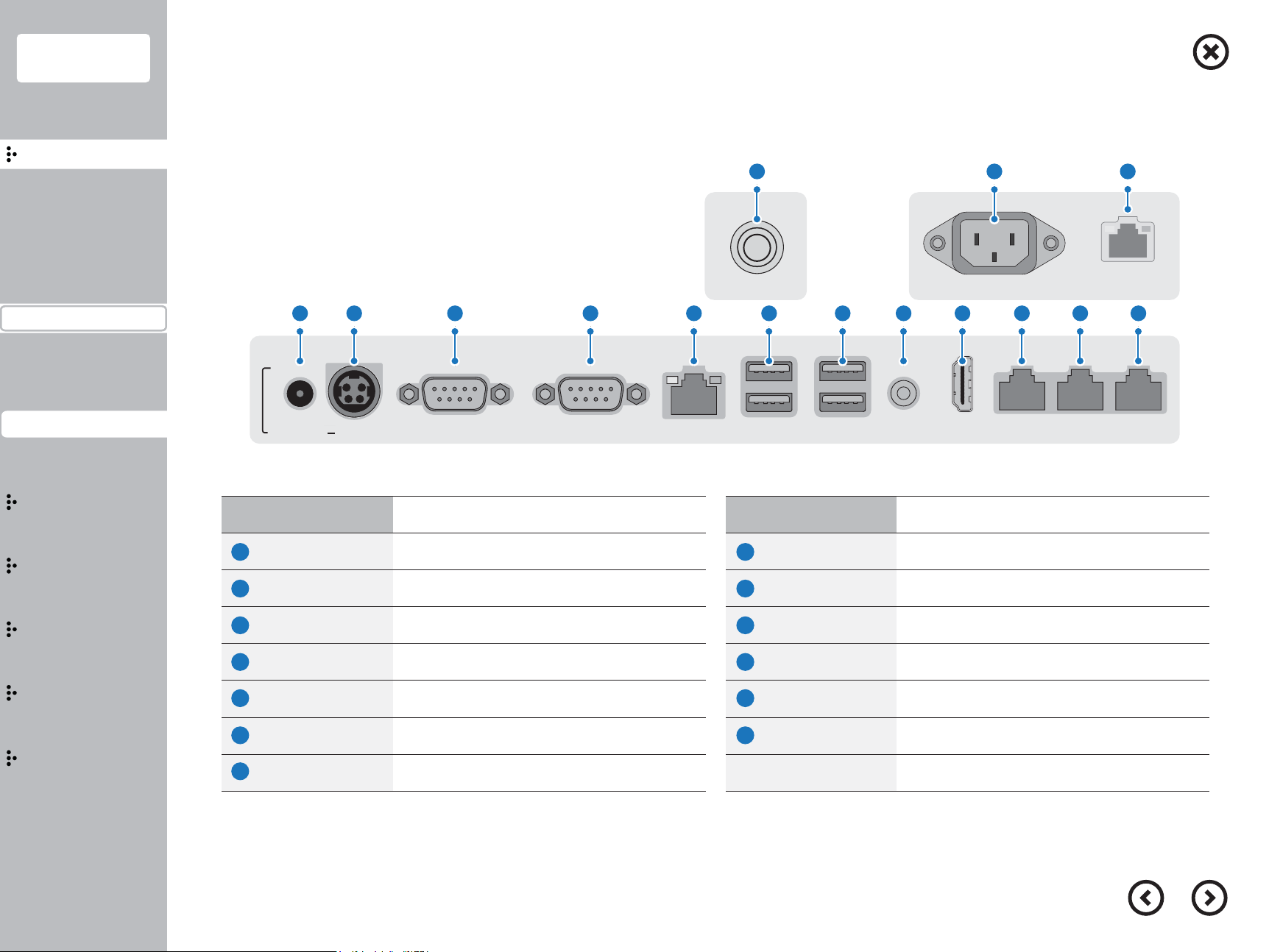
Interface
PS2 -
Audio 1 EA (Line-Out)
LAN 1 EA (RealTek Gigabit LAN)
USB 4 EA (I/O) (USB3.0 & 2.0) + 2 EA (Rear) (USB2.0)
Display 17" TFT-LCD, LVDS, 1280 X 1024, 24-BIT
Serial 5 EA (DSUB-9p x 2EA / RJ-45 x 3EA)
Graphic & Touch screen
Dispaly 17" TFT-LCD, LVDS, 1280 X 1024, 24-BIT
Luminance : 250 cd/㎡, Backlight : LED
Chipset System on chip (SoC)
Touch type 17"Bezel type, 5-Wire Resistive
17”Bezelless type, Projected Capacitive Touch
Power
Power source 60[W] Adaptor
Input AC 100~240V/50~60HZ, DC 12V/5A
Option
OS Microsoft® POSReady7 / Windows 10 IoT
Linux / Android
Speaker 1 EA (1W)
(Wall Mount) Possible(Optional)
EFT terminal Verifone VX 820(Optional)
5
Contents
Introduction
Caution
Introduction
Specification&Options
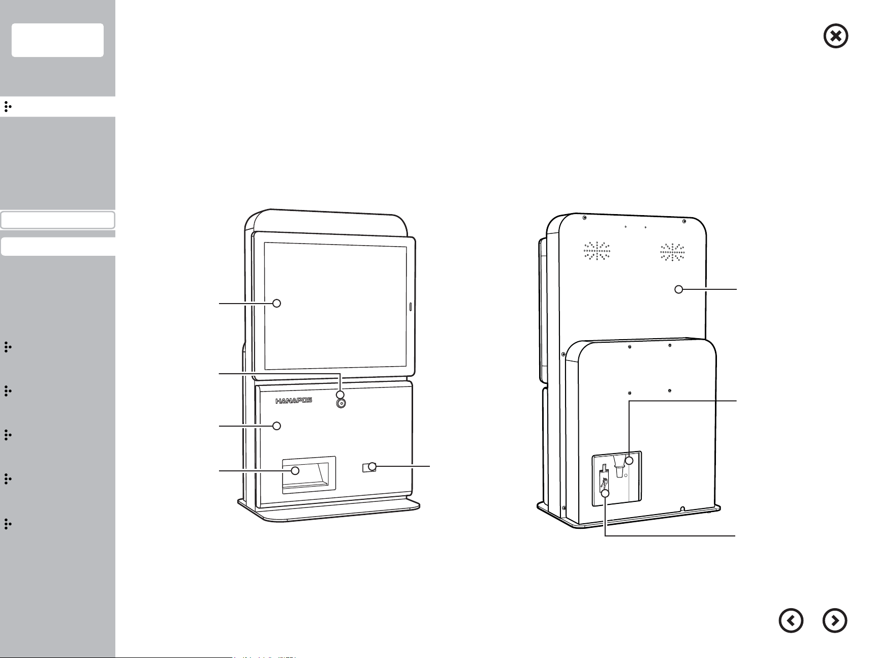
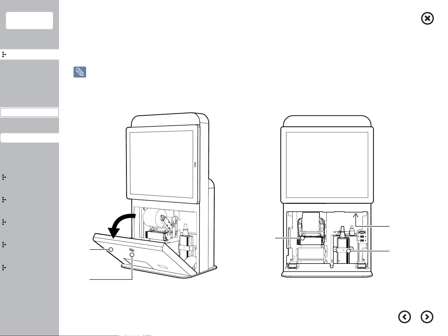
Part name&Function
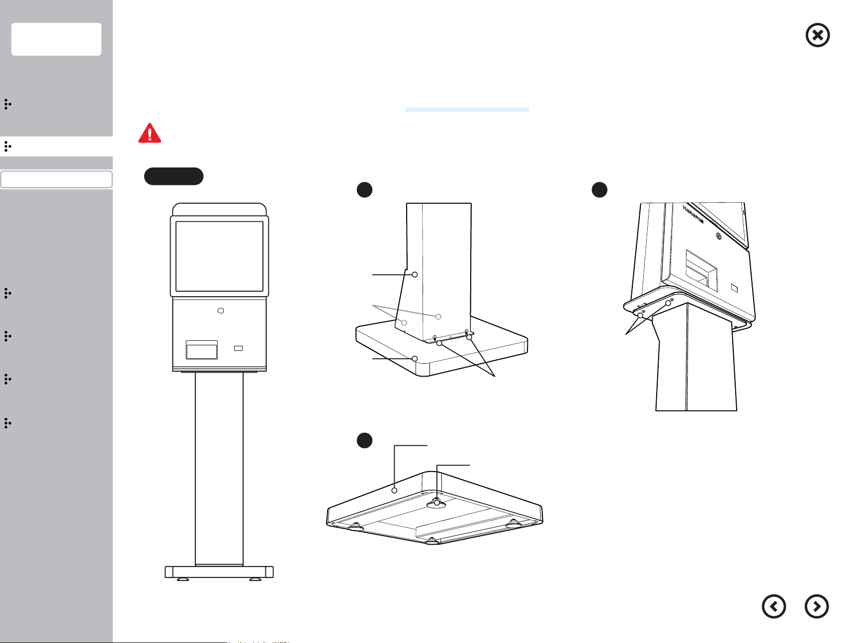
Installation
Usage
Extension
Bios
Configuration
■
Specification and Options
Specification and Options