manuals.online logo
Brands
  1. Home
  2. •
  3. Brands
  4. •
  5. protech
  6. •
  7. Digital Signage
  8. •
  9. protech PA-1822 User manual

protech PA-1822 User manual

USER
MANUAL
PA-1822
Semi-SelfService
PaymentKiosk
PA-1822 M0
PA-1822 15” Semi-Self Service
Payment Kiosk With 10.4”
Customer Touch Display
COPYRIGHT NOTICE & TRADEMARK
All trademarks and registered trademarks mentioned herein are the
property of their respective owners.
This manual is copyrighted in Oct. 2016. You may not reproduce or
transmit in any form or by any means, electronic, or mechanical,
including photocopying and recording.
DISCLAIMER
This user’s manual is meant to assist users in installing and setting up
the Kiosk. The information contained in this document is subject to
change without any notice.
CE NOTICE
This is a class A product. In a domestic environment this product may
cause radio interference in which case the user may be required to take
adequate measures.
FCC NOTICE
This equipment has been tested and found to comply with the limits for
a Class A digital device, pursuant to part 15 of the FCC Rules. These
limits are designed to provide reasonable protection against harmful
interference when the equipment is operated in a commercial
environment. This equipment generates, uses, and can radiate radio
frequency energy and, if not installed and used in accordance with the
instruction manual, may cause harmful interference to radio
communications. Operation of this equipment in a residential area is
likely to cause harmful interference in which case the user will be
required to correct the interference at his own expense.
You are cautioned that any change or modifications to the equipment
not expressly approve by the party responsible for compliance could
void your authority to operate such equipment.
CAUTION: Danger of explosion may occur when the battery
is incorrectly replaced. Replace the battery only with the
same or equivalent type recommended by the manufacturer.
Dispose of used batteries according to the manufacturer’s
instructions.
WARNING: Some internal parts of the Kiosk may have high
electrical voltage. We strongly recommend that only qualified
engineers are allowed to service and disassemble the Kiosk.
If any damages should occur on the Kiosk and are caused by
unauthorized servicing, it will not be covered by the product
warranty. Please operate the LCD and Touchscreen with
extra care as they can break easily.
1Introduction
This chapter provides the introduction for the PA-1822
Kiosk as well as the framework of the user manual.
The following topics are included:
•About This Manual
Chapter 1 Introduction
Page: 1-2
1.1 About This Manual
Thank you for purchasing our PA-1822 Semi-Self Service Payment Kiosk. The
PA-1822 is an updated system designed to be comparable with the highest
performance of IBM AT personal computers. The PA-1822 provides faster processing
speed, greater expandability and can handle more tasks than before. This manual is
designed to assist you how to install and set up the whole system. It contains four
chapters and three appendixes. Users can configure the system according to their own
needs. This user manual is intended for service personnel with strong hardware
background. It is not intended for general users.
Chapter 1 Introduction
This chapter introduces PA-1822 Kiosk general information and the framework of
PA-1822 user manual.
Chapter 2 Getting Started
This chapter includes the physical illustrations, quick setup and specifications for the
PA-1822 system. Read the safety reminders carefully on how to take care of your
system properly.
Chapter 3 System Configuration
This chapter outlines the locations of the motherboard and sensor board components
and their respective functions. You will learn how to set the jumpers and configure the
system to meet your own needs.
Chapter 4 Software Utilities
This chapter contains helpful information for proper installations of the “DRIVER &
SDK” which comes in a DVD-ROM format, how to change the AMI BIOS
configurations, and Watchdog Timer Configuration, Flash BIOS Update and ACPI
functions list.
Chapter 5 System Diagrams
This appendix provides the exploded diagrams and part numbers of the PA-1822.
CAUTION
FOR YOUR TROUBLESHOOTINGNEEDS, CONSULT
THESE MODULES' USER'S GUIDES INCLUDED IN PA-1822
User MANUALFILE.
YOU MAY ALSO CONTACT OUR SERVICE WINDOW FOR
TECHNICALASSISTANCE.

2Getting Started
This chapter provides the information for the PA-1822
system. It describes how to set up the system quickly and
outlines the system specifications.
The following topics are included:
•Package List
•System Overview
•System Specification
•Safety Precautions
Experienced users can go to Chapter 3 System
Configuration on page 3-1 for a quick start.
Chapter 2 Getting Started
Page: 2-2
2.1 Package Contents
If you discover any of the items listed above are damaged or list, please
contact your local distributor immediately.
No. Item Q’ty
1 PA-1822 Semi-Self Service Kiosk 1
2 PA-1822 Quick Reference Guide 1
3 Manual/Driver DVD 1
4 AC Power Cord 1
Front View
Rear View
Side View
Chapter 2 Getting Started
2.2 System Overview
Chapter 2 Getting Started
Page: 2-3
450
600
600
10.4"
Customer
Touch
Display
Maintenance Door
Printer
Drawer
15" Touch
Panel-PC
for Sales
Clerk
Reserved space
for "Credit Card
Reader"
Maintenance
Cover
Chapter 2 Getting Started
Page: 2-4
Coin insert
Note
insert
Change
Area Scanner
Power
Button
Insert Coin
Insert Cash
Get receipt
Credit Card
(customer
consign)
Get change back
Coin Acceptor
Bill Acceptor
Credit Card
Reader
Change area Thermal
printer
PAYMENT function relevant
Chapter 2 Getting Started
Page: 2-5
Scan
Barcode
Reader
2.3 System Specifications
System
Customer Side
printer running
Power
Consumption
AC W
AC W
AC W
AC W
Chapter 2 Getting Started
Page: 2-7
2.4 SAFETY PRECAUTIONS
The following messages are safety reminders on how to protect your systems from
damages; thus extending the life cycle of the system.
1. Check the Line Voltage
a. The operating voltage for the power supply should be within the range of
100V to 240V AC; otherwise the system may be damaged.
2. Environmental Conditions
a. Place your PA-1822 on a sturdy, level surface. Be sure to allow enough
space around the system to have easy access needs.
b. Avoid installing your PA-1822 Series POS system in extremely hot or cold
places.
c. Avoid exposure to sunlight for a long period of time (for example, in a
closed car in summer time. Also avoid the system from any heating device.).
Or do not use the PA-1822 when it has been left outdoors in a cold winter
day.
d. Bear in mind that the operating ambient temperature is between 0°C and
35°C (32°F and 95°F).
e. Avoid moving the system rapidly from a hot place to a cold place, and vice
versa, because condensation may occur inside the system.
f. Protect your PA-1822 against strong vibrations, which may cause hard disk
failure.
g. Do not place the system too close to any radio-active device. Radio-active
device may cause signal interference.
h. Always shut down the operation system before you power off the system.
3. Handling
a. Avoid placing heavy objects on the top of the system.
b. Do not turn the system upside down. This may cause the hard drive to
malfunction.
c. Do not allow any objects to fall into this product.
d. If water or other liquid spills into the product, unplug the power cord
immediately.
Chapter 2 Getting Started
Page: 2-35
3System Configuration
This chapter contains helpful information about the various
component modules comprised in PA-1822 as well as the
BIOS operation.
PA-1822 consists of the component modules as below:
• 01. 2D Scanner_RIOTEC FS5022J
• 02. 10.4 Inch Touch Monitor_PHISTEK P104VR
• 03. 3-Inch Printer_EPSON Kit
• 07. Note Acceptor_JCM Vega-RC Twin
• 09. Coin System_Innovative Smart Coin System
• 08. 15-Inch Panel-PC_Prox PA-6322-PPC
3-1. 01. 2D Scanner_RIOTEC FS5022J
Chapter 3 System Configuration
Page: 3-2
3-2. 02. 10.4 inch Touch Monitor_PHISTEK P104VR
Cabinet Color
Cover Lens
Display type
Resolution
Brightness
Contrast ratio
Response Time
LCD Viewing Angle
I/O Connectivity
Power consumption
Temp(Operation/Storage)
Humidity
Certificate
Resistive Touch Panel
Black
PMMA Hardness> 5H(JIS D0202) ,T> 93%
10.4” TFT active matrix with LED backlight
800 x 600 (support 1024 * 768 @60Hz)
300 nits (typical)
500:1 (typical)
30ms (typical)
110 (H) / 150 (V) degrees
VGA D-Sub 15 pins, DC 12V
6W
0~40 degrees C / -10~50 degrees C
20% to 90% non-condensing
CE , FCC, BSMI
Five-Wire Analog Resistive
USB type, eGalax Touch Control Drive
Chapter 3 System Configuration
Page: 3-3
3-3. 03. 3-Inch Printer_EPSON M-T532IIAP-000
Power Supply Connector
This connector is used to connect the printer to an external power source.
1) Pin assignments: See the following table.
2) User side connector model: Housing: 5195-04 (MOLEX)
5194Terminal: (MOLEX)
Table. Power Supply Connector Pin Assignments
Pin Number Signal Name
1 GND
2 +24 VDC
3 +24 VDC
4 GND
NOTES:
1. Be sure to ground the frame ground of the BA-T500II by installing screws.
2. Be sure to connect all four pins.
1 2 3 4
CN1
Printer
Connector
26-pin FFC
connector for
the thermal
print head
15-pin FFC
connector for
the printer
mechanism
CN4
CN5
Control Board
USB
Interface
Connector CN21
Chapter 3 System Configuration
Page: 3-4
Near-end sensing position
Paper Near-End Sensor
Open the "Paper Holder" when you need to :
1. Clear a paper jam
2. Take out the thermal paper as
shown right. ※ The "Paper Holder" won't
open if paper has run out.
※Make sure the "Paper Holder"
is closed before you feed paper.
Paper
Holder
CAUTION
FOR YOUR TROUBLESHOOTING NEEDS, CONSULT THE
ATTACHED DOCUMENT "3-Inch Printer_EPSON Kit"
of "PA-1822 e-MANUAL” OR CONTACT OUR SERVICE
WINDOW.
Printer module built in with auto-cutter
Chapter 3 System Configuration
Page: 3-5
3-9. 05. Coin Hopper_Innovative SMART Hopper
Remove the SCS from the mounting plate.
Pull Handle
Pull Out the Hopper
I/O Panel
CAUTION
FOR MORE INFORMATION AND YOUR TROUBLESHOOTING
NEEDS, PLEASE SEE THE ATTACHED DOCUMENT
"09. SMART-coin-system-technical-manual" of "PA-1822 e-
MANUAL" or CONTACT OUR SERVICE WINDOW.
Chapter 3 System Configuration
Page: 3-9
3.1 Preparation
If you received your Smart Coin System already mounted on the
baseplate, remove it.
slide off
Indicator Flash Codes
Status LED’s
Chapter 3 System Configuration
Page: 3-10
A summary of the Status Indicator Flash Codes for the payout module are shown here:
Led Colour Status Description Action
Green Flashing
1Hz
Enabled and ready to
dispense
Red 1 Flash Hopper disabled Host system to send
enables command.
Red 2 Flashes Calibration Fault Optical sensor contaminated.
Operator to clean exit sensor
light pipe. If fault persists,
return to ITL for service.
Red 3 Flashes No Encryption key set Host system to negotiate key.
Red 4 Flashes Coin jammed Remove power, manually
empty coins from bowl and
check hopper base for stuck
coins. Try manually turning
the disc. Persistent jam
may require returning to
ITL for service.
Red 5 Flashes Fraud Attempt detected. Reset hopper. If this
persists it indicates a
problem with the top pay-
out flap, light guide or exit
sensor.
Red 6 Flashes Legacy, no longer used.
(Hopper empty)
Red 7 Flashes Memory checksum error Re-download hopper
firmware. If this persists
return to ITL for service.
Red 8 Flashes Hopper sensors not
initialised
Return to ITL for
service.
Red 9 Flashes Legacy, no longer used. (Lid
removed).
CAUTION
FOR MORE INFORMATION AND YOUR TROUBLESHOOTING
NEEDS, PLEASE SEE THE ATTACHED DOCUMENT
"07. Note Acceptor_JCM Vega-RC Twin" of "PA-1822
e-MANUAL" or CONTACT OUR SERVICE WINDOW.
3-7. 07.Note Acceptor_JCM Vega-RC Twin
PinSignal
NameI/OFunction
1VDD1‐12VDC
2VSS1‐GND
3RS232C
‐RXDINSerialdatasignalinputline
fromControllertoValidator
8SG‐SignalGround
14RS232
‐TXDOUT
Serialdatasignaloutputline
fromValidatortoController
(RS232Coutputlinealternative)
LED Pattern Color Indications
Description Sequence Condition
Power Supply
RAM Error
(interval: 0.3sec)
Normal Boot
Download Download Mode
Downloading While downloading from
the host (VEGA or PC)
(interval: 0.5sec)
Download
Complete Software Reset
Restore
Retrieve
Dispense Stand-by
Description Sequence Condition
Restoring
Retrieving
Dispensing Normal Operation
(interval: 0.5sec)
Initialize
Indications
Initial Movement
(interval: 0.5sec)
Door open
(interval: 0.5sec)
Banknote jam occurs
(interval: 0.5sec)
Communication
with VEGA Unit Waiting for commun
-ication from a VEGA
Unit(interval: 0.5sec)
Door Open While in Normal
Operation (interval:
0.5sec)
Error Error occurs
(Machine Lock)
DS1 /DS2
default setting
12345678
offoffoffoffoffoff off off
Chapter 3 System Configuration
Page: 3-12

Other protech Digital Signage manuals

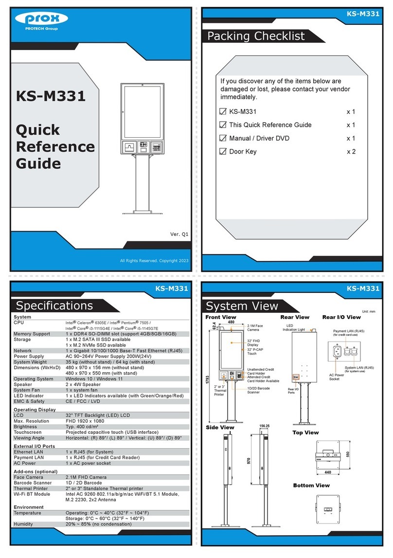
protech KS-M331 User manual

protech

protech KS-M331 User manual

protech prox KF-P231 User manual

protech

protech prox KF-P231 User manual

protech KS-1132 User manual

protech

protech KS-1132 User manual

protech KF-7131 User manual

protech

protech KF-7131 User manual

protech prox SP-C085 User manual

protech

protech prox SP-C085 User manual

protech prox KF-P230 User manual

protech

protech prox KF-P230 User manual

protech KS-1130 User manual

protech

protech KS-1130 User manual

protech KS-M320 User manual

protech

protech KS-M320 User manual

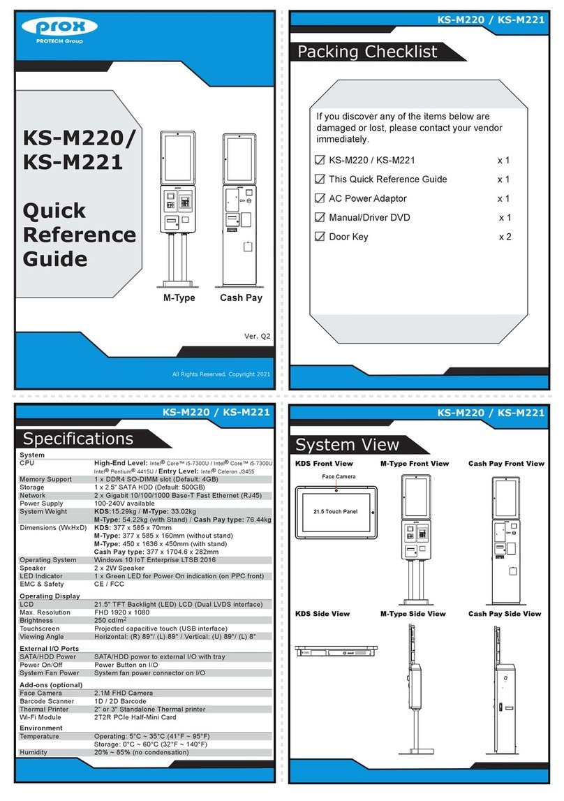
protech prox KS-M220 User manual

protech

protech prox KS-M220 User manual

protech KT-7290 User manual

protech

protech KT-7290 User manual

protech KF-7270 User manual

protech

protech KF-7270 User manual

protech MD-591X User manual

protech

protech MD-591X User manual

protech prox KF-P230 User manual

protech

protech prox KF-P230 User manual

protech KS-M331 User manual

protech

protech KS-M331 User manual

protech prox KS-M220 User manual

protech

protech prox KS-M220 User manual

Popular Digital Signage manuals by other brands

hanshow Nebular Series product manual

hanshow

hanshow Nebular Series product manual

Kramer AVDS user manual

Kramer

Kramer AVDS user manual

DFI DS910-OT quick start guide

DFI

DFI DS910-OT quick start guide

LG 72WX70MF-B.APD owner's manual

LG

LG 72WX70MF-B.APD owner's manual

I-Frame HOME user manual

I-Frame

I-Frame HOME user manual

LG 55VH7BAW-9P owner's manual

LG

LG 55VH7BAW-9P owner's manual

Shuttle D230 quick start guide

Shuttle

Shuttle D230 quick start guide

AXIOMTEK OPS883 Series Quick installation guide

AXIOMTEK

AXIOMTEK OPS883 Series Quick installation guide

LG 86TN3F-B owner's manual

LG

LG 86TN3F-B owner's manual

LG 55LS35A owner's manual

LG

LG 55LS35A owner's manual

PC Vision ADM-4X user manual

PC Vision

PC Vision ADM-4X user manual

LG 98UH5E manual

LG

LG 98UH5E manual

Mobibooth Aura V2 Photo Kiosk Setup guide

Mobibooth

Mobibooth Aura V2 Photo Kiosk Setup guide

LG 55SM5KD Service manual

LG

LG 55SM5KD Service manual

LG 55EW5F installation guide

LG

LG 55EW5F installation guide

LG 55VL7F-A owner's manual

LG

LG 55VL7F-A owner's manual

LG 8LG55UH5CBAEK owner's manual

LG

LG 8LG55UH5CBAEK owner's manual

LG 88BH7D-B manual

LG

LG 88BH7D-B manual

manuals.online logo
manuals.online logoBrands
  • About & Mission
  • Contact us
  • Privacy Policy
  • Terms and Conditions

Copyright 2025 Manuals.Online. All Rights Reserved.