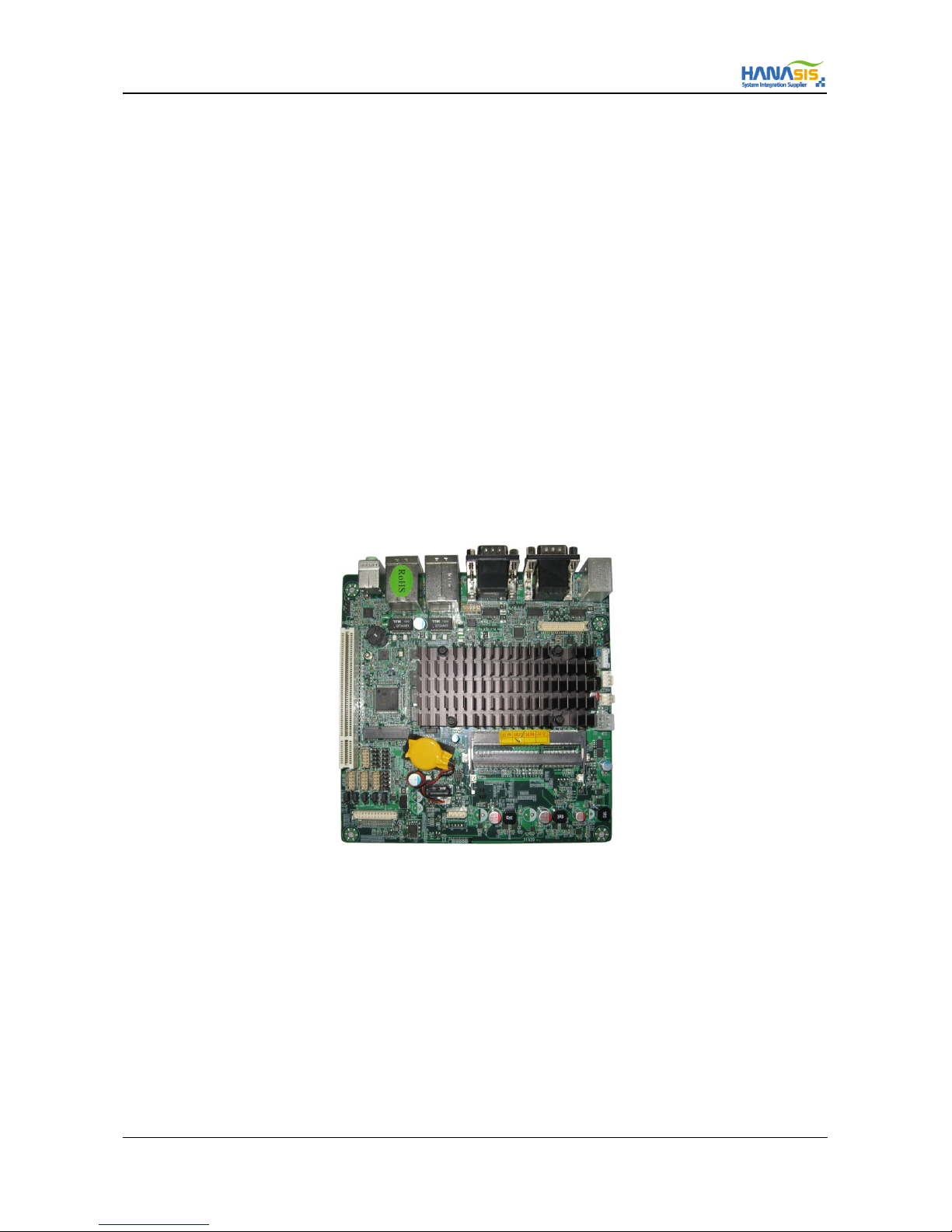
ITX-D255R Mini-ITX Mother Board Manual
10 / 31
2.4 Expansion Slot (PCI Slot)
There is 1 PCI slot on this motherboard.
PCI Slot : The PCI slot is used to install an expansion card that has 32-bit PCI interface.
2.4.1 Installing a Expansion Card
Step#1] Before installing the expansion card, please make sure that the power supply is switched off or the power cord is unplugged.
Please read the documentation of the expansion card and make necessary hardware settings for the card before you start
the installation.
Step#2] Remove the system unit cover (if your motherboard is already installed in a chassis).
Step#3] Remove the bracket facing the slot that you intend to use. Keep the screws for later use.
Step#4] Align the card connector with the slot and press firmly until the card is completely seated on the slot.
Step#5] Fasten the card to the chassis with screws. Step 6. Replace the system cover.
2.5 Jumper Setup
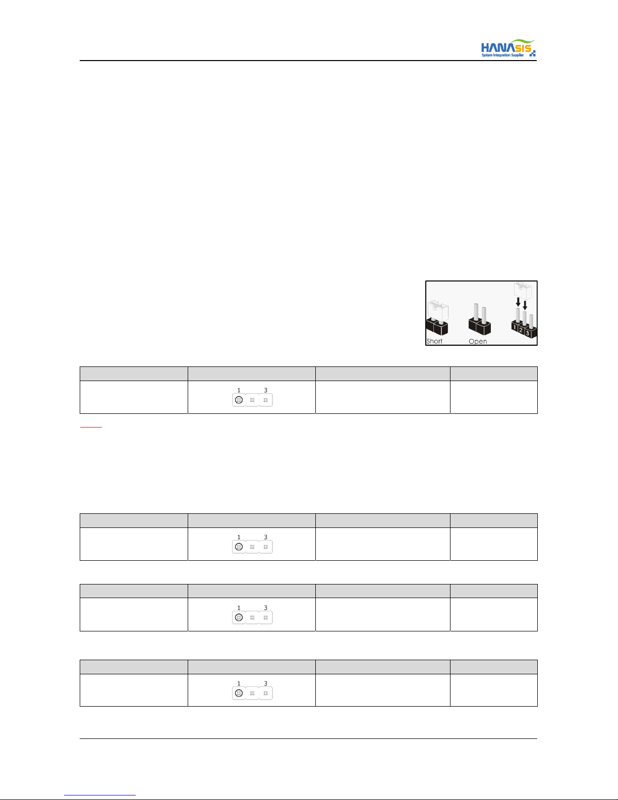
The illustration shows how jumpers are setup. When the jumper cap is placed on pins,
the jumper is “Short”. If no jumper cap is placed on pins, the jumper is “Open”.
The illustration shows a 3-pin jumper whose pin1 and pin2 are “Short”
when jumper cap is placed on these 2 pins.
2.5.1 Clear CMOS Jumper (JCMOS)
Connector SPEC Shape Jumper Description Remark
3-Pin 2.54 Pitch
1 - 2 : Normal
2 - 3 : Clear CMOS Default is Normal
NOTE] JCMOS allows you to clear the data in CMOS. To clear and reset the system parameters to default setup, please turn off the
computer and unplug the power cord from the power supply. After waiting for 15 seconds, use a jumper cap to short pin2 and pin3 on
JCMOS for 5 seconds. However, please do not clear the CMOS right after you update the BIOS. If you need to clear the CMOS when you
just finish updating the BIOS, you must boot up the system first, and then shut it down before you do the clear-CMOS action. Please be
noted that the password, date, time, user default profile and MAC address will be cleared only if the CMOS battery is removed.
2.5.2 Panel Power Jumper (JLV)
Connector SPEC Shape Jumper Description Remark
3-Pin 2.54 Pitch
1 - 2 : +3.3V (LCD 15”)
2 - 3 : +5.0V (LCD 17”) Default is +3.3V
2.5.3 AT/ATX Mode Jumper (JAT/ATX)
Connector SPEC Shape Jumper Description Remark
3-Pin 2.54 Pitch
1 - 2 : AT Mode
2 - 3 : ATX Mode (Button On) Default is ATX Mode
2.5.4 COM(4~6) Port Power Setting Jumper (JCOM4/JCOM5/JCOM6 PWR)
Connector SPEC Shape Jumper Description Remark
3-Pin 2.54 Pitch
1 - 2 : +5 V
2 - 3 : +12V Default is +5V