Hanbay RC-AC Series User manual

Page 1 of 17 www.hanbayinc.com | 1 800 315 4461
Rev.2021.11 hanbaysales@hanbayinc.com
*Only model numbers:
RCx-AC-BxxAx w/ ex-proof
lid engraving (see p.12)
RCx-AC-xxxAx-8.09
(110-240 VAC; 4-20 mA Control)
CSA/IECEX Rated*
USER MANUAL
Contents
INSTALLATION 2
Mounting 2
Wiring 2
Wiring for Explosion Proof Actuators 2
Wiring for Non-Explosion Proof actuators 3
Power Supply and Current Draw 4
Control Signal and Feedback 5
OPERATION 6
DIP Switches 6
Controlling the Actuator 7
Changing the number of turns 7
Torque Settings 8
Speed and Torque Details 8
Signal Loss and Calibration 10
Manual Override 11
Troubleshooting 11
EXPLOSION PROOF CERTIFICATIONS 12
ACTUATOR DIMENSIONS 13
PART NUMBER BREAKDOWN 16
LABEL BREAKDOWN 17

User Manual RCx-AC-xxxAx-8.09
Page 2 of 17 www.hanbayinc.com | 1 800 315 4461
Rev.2021.11 hanbaysales@hanbayinc.com
INSTALLATION
Mounting
The holes indicated in the image are intended for a mounting
bracket. They are threaded for ¼-20 and are 0.4” deep.
The other two visible holes are threaded 10-32, 0.50” deep, and
are intended to be used to lock the lid in position with screws.
For detailed dimensions see p.13.
Wiring
Wiring for Explosion Proof Actuators
The RCx-AC-BxxAx Explosion-Proof actuator does not come with a pre-installed cable, nor
cable gland. A cable gland that meets site specifications for the appropriate hazardous location
rating is required for installation. The cable gland and the cable for hazardous location should
be installed by qualified personnel in accordance with site and local requirements.
The actuator comes standard with a ½” FNPT thread cable entry. See p.13 for
location of ½” FNPT housing access. A cable with 6 wires is required; it is
recommended to use 3x 16 AWG for wires supplying power and ground, and 3x 20
AWG for wires used for the control and feedback signals.
Standards for cable gland and cable in hazardous locations:
* In explosion-proof models, the FNPT thread is not intended for conduit connection. Cable gland only.
Compliance Standards
Required to be Met
Cable Types Permitted in
Class I Division 1
Hazardous Locations
ANSI / UL 514B, ANSI / UL
1203, ANSI / UL 2225, C22.2
Non-Armored Extra Hard
Usage Cord & TC-ER-HL
ANSI / UL 514B, ANSI / UL
1203, ANSI / UL 2225
Armored IEEE 45 & IEEE
1580 Marine Shipboard Cable
ANSI / UL 514B, ANSI / UL
1203, ANSI / UL 2225
MC-HI, ITC-HL
ANSI / UL 514B, ANSI / UL
1203, C22.2
Teck 90 (Canada Only)

User Manual RCx-AC-xxxAx-8.09
Page 3 of 17 www.hanbayinc.com | 1 800 315 4461
Rev.2021.11 hanbaysales@hanbayinc.com
Once the cable and cable gland are installed, connect the wires to the pins on the terminal block as
indicated here:
Wiring for Non-Explosion Proof actuators
The actuator comes standard with a pre-installed cable gland and a 10’ cable. Cut the cable to the length
required, then connect according to the following wire color schematic:
Wire color schematic for cable
Pin
Function
6
Pre-wired to transformer
Connect live wire to loose black cable
with crimp connector (see p.4)
5
Pre-wired to transformer
Connect neutral wire to loose white
cable with crimp connector (see p.4)
4
Feedback signal (4-20 mA)*
3
Not connected
2
Isolated** input signal gnd.
1
Isolated** input signal (4-20 mA)
Colour
Function
Red (1)
Live 110-240 VAC (16 AWG)
Black (2)
Neutral 110-240 VAC (16 AWG)
Blue (3)
Ground (16 AWG)
Green (4)
Not connected
Grey (5)
Feedback* signal (20 AWG)
Yellow (6)
Isolated** input signal gnd. (20 AWG)
Blue (7)
Isolated** input signal 4…20 mA (20 AWG)
Remove R66 to
convert from 4…20
mA to 1-5 V input
signal
Terminal
123456
* “feedback” available in RCx-AC-xxxAFversion only
** “isolated” available in RCx-AC-xxxAIand xxxAFversions only
* “feedback” available in RCx-AC-xxxAFversion only
** “isolated” available in RCx-AC-xxxAIand xxxAFversions only

User Manual RCx-AC-xxxAx-8.09
Page 4 of 17 www.hanbayinc.com | 1 800 315 4461
Rev.2021.11 hanbaysales@hanbayinc.com
Power Supply and Current Draw
The RCx-AC-xxxAx actuator may be connected to voltages within
110-240 VAC.
The current draw will range from minimum 10 mA to maximum 1.5 A while
the actuator is active. When not moving, the actuator draws approx. 5 mA.
AC power is connected to the WHITE & BLACK wires with crimp
connectors (WM18225-DN & WM18230-ND 18-22 AWG).
Ground is connected on the GREEN ground screw, shown below.
AC Input
Black –Live
White –Neutral
Internal Wires for 24 VDC
(Already Connected)
White +24 VDC
Black 0 VDC
Ground Connection
AC Voltages
AC Gnd common to PWR Gnd

User Manual RCx-AC-xxxAx-8.09
Page 5 of 17 www.hanbayinc.com | 1 800 315 4461
Rev.2021.11 hanbaysales@hanbayinc.com
Control Signal and Feedback
Locate the correct connection terminals/wires as shown on the previous page, then connect your input signal
on positions 1 and 2 (yellow and blue wires) as shown below. Feedback, if applicable, is connected to
position 4 (grey wire).
1 2 3 4 5 6
P1
4-20 mA Signal source,
user powered
-
+
Actuator
MCx-AC-xxxAx
Internal
RES
R66
NOTE 1: Usually, the actuators are
shipped for 4-20 mA signal input.
For 1-5 V signal input, remove 250
ohm resistor R66.
The actuator 4-20 mA output is internally supplying the signal current and can drive sufficient voltage for any
sensing resistor of up to 250 ohms.
The potential of the external GND after the sensing resistor may not be more than +6 VDC / -2 VDC away from
the power GND of the actuator.
This feedback signal output is only available in HANBAY RCx-AC-xxxAF model actuators.
External
4-20 mA
Sensing
resistor
NOTE 2: Signal Gnd. is NOT
ISOLATED from Power Gnd. in all
RCx-AC-xxxAB basic models.
If your signal Gnd. is different from
Power Gnd. use HANBAY RCx-AC-
xxxAI or RCx-AC-xxxAF model
actuators.
NOTE 3: DO NOT CONNECT pin 4
directly or through a multimeter only
to ground.
A sensing resistor of 50 ohms or more
needs to be present.
Not observing this warning will
damage the equipment.
NC

User Manual RCx-AC-xxxAx-8.09
Page 6 of 17 www.hanbayinc.com | 1 800 315 4461
Rev.2021.11 hanbaysales@hanbayinc.com
OPERATION
DIP Switches
The DIP switches allow you to change the
settings on your actuator. To flip a switch,
gently use a small flat-head screwdriver.
See table below for DIP switch functionality.
DIP
Function
1
2
Speed: Choose how quickly the actuator will turn the valve. See p.8.
3
Only in the ON position for actuator model RCH (with external gear stage).
4
5
6
7
8
Turns: The actuator usually ships from the factory with the recommended number of turns for the
valve. However, this number can be changed. Turning on a switch will add a specific number of
turns to the actuator’s movement.
See p.8 for relation between positions of the DIP switches and number of turns.
Example: Turning on DIP 6 adds four turns, turning on DIP 8 adds one turn. If both DIP 6 and 8 are
on, then the total turns of the actuator would be five.
9
Signal loss: See p.10.
10
11
Seating torque: Set how much torque the actuator exerts on the valve lever during the calibration
(finding valve seat) procedure. See p.8.
12
Direction/Calibration: Toggle switch on and off while powered to re-calibrate actuator (find valve
seat). Also sets direction in which the actuator will open and close. See p.10.
Example: The RCM model actuator turns clockwise when the signal is decreased with DIP 12 in the
OFF position. Putting DIP 12 in the ON position will cause counter-clockwise turning for a decrease
in signal. For changes in DIP 12 position to take effect, the power to the actuator must be cycled.
In this example DIPs 1, 2, 5 and 12 are on.

User Manual RCx-AC-xxxAx-8.09
Page 7 of 17 www.hanbayinc.com | 1 800 315 4461
Rev.2021.11 hanbaysales@hanbayinc.com
Controlling the Actuator
The 4-20 mA (or 1-5 V / 1-10 V) input signal represents a total span of a number of turns.
I.e.: If you set the number of turns to 2, then a signal of 12 mA will set the actuator to exactly 1 turn from the
fully closed position. 15 mA will give: (15-4)/16=0.6875 ⇒68.75% of 2 turns ⇒1.375 turns from closed.
Changing the number of turns
With the DIP switch settings, you can adjust anything between 1 and 31 turns to represent the full signal
range of 4-20 mA. Check in the table below. (1 = “On”, 0 = “Off”).
Total Turns
Dip4=0
DIP 5
DIP 6
DIP 7
DIP 8
reserved
0
0
0
0
1
0
0
0
1
2
0
0
1
0
3
0
0
1
1
4
0
1
0
0
5
0
1
0
1
6
0
1
1
0
7
0
1
1
1
8
1
0
0
0
9
1
0
0
1
10
1
0
1
0
11
1
0
1
1
12
1
1
0
0
13
1
1
0
1
14
1
1
1
0
15
1
1
1
1
WARNING: Be sure that the number of turns the actuator is set for is LESS than the number of
turns for the valve. The actuator should not stop itself on a fully opened valve. It can damage the
valve, and the actuator will lose its position.
For more turns, set DIP 4 to the ON position.
This will add 16 turns to the number set by DIPs
5 through 8, as shown in the table.
DIP 4=0
+0 turns
DIP 4=1
+16 turns

User Manual RCx-AC-xxxAx-8.09
Page 8 of 17 www.hanbayinc.com | 1 800 315 4461
Rev.2021.11 hanbaysales@hanbayinc.com
Torque Settings
To accommodate different valves and other applications
with different torque requirements, the actuator can be set
to apply different torque on the valve stem when in the
seating mode.
During normal operation, the actuator will try to reach the
speed set by DIP 1 and DIP 2. It will use 100% torque to try
and reach the selected speed, regardless of the positions of
DIP 10 and DIP 11. Current draw is limited to 1.5 A
regardless of settings.
Please see the box to the right and the tables below to select the power setting that is right for your
application.
To deal with sticking valves, at the beginning of the first reversing movement after the seating (“zeroing”) of
the valve, the actuator will apply double the power set by DIP 10 and DIP 11 (up to 100% power.)
This “pull out” function is always enabled.
Speed and Torque Details
The maximum speed of the actuator can be set by using the first two positions of the DIP switch selector.
As a result of this setting, the actuator will limit the maximum speed. The tables below show the time required
to complete one turn.
The seating torque depends on the voltage provided in the power connection and on the
seating power settings on DIP 10, 11 as shown below.
RCL-AC-xxxAx Actuators
Speed:
Torque:
DIP 1
DIP 2
Time for
1 turn (sec)
DIP 10
DIP 11
Seating Torque
(in-lbs)
Operating
torque is
100%
OFF
OFF
7
OFF
OFF
12
OFF
ON
3
OFF
ON
20
ON
OFF
2
ON
OFF
38
ON
ON
1
ON
ON
48
NOTE: If actuator is RCJ-AC-xxxAx, divide torque values by 3.
To convert in-lbs to Nm, divide by 9.
WARNING: High power settings can supply enough torque to damage your valve.
Please be cautious, especially when using the 100% power setting.
Seating power settings:
DIP 10
DIP 11
Power
OFF
OFF
16%
OFF
ON
33%
ON
OFF
66%
ON
ON
100%

User Manual RCx-AC-xxxAx-8.09
Page 9 of 17 www.hanbayinc.com | 1 800 315 4461
Rev.2021.11 hanbaysales@hanbayinc.com
RCM-AC-xxxAx Actuators
Speed:
Torque:
DIP 1
DIP 2
Time for
1 turn (sec)
DIP 10
DIP 11
Seating Torque
(in-lbs)
Operating
torque is
100%
OFF
OFF
23
OFF
OFF
35
OFF
ON
11
OFF
ON
60
ON
OFF
7
ON
OFF
115
ON
ON
4
ON
ON
145
NOTE: If actuator is RCK-AC-xxxAx, divide torque values by 3.
To convert in-lbs to Nm, divide by 9.
RCH-AC-xxxAx Actuators
Speed:
Torque:
DIP 1
DIP 2
Time for
1 turn (sec)
DIP 10
DIP 11
Seating Torque
(in-lbs)
Operating
torque is
100%
OFF
OFF
90
OFF
OFF
120
OFF
ON
45
OFF
ON
205
ON
OFF
30
ON
OFF
400
ON
ON
18
ON
ON
497
To convert in-lbs to Nm, divide by 9.
RCF-AC-xxxAx Actuators
Speed:
Torque:
DIP 1
DIP 2
Time for
1 turn (sec)
DIP 10
DIP 11
Seating Torque
(in-lbs)
Operating
torque is
100%
OFF
OFF
186
OFF
OFF
230
OFF
ON
94
OFF
ON
380
ON
OFF
56
ON
OFF
720
ON
ON
38
ON
ON
915
To convert in-lbs to Nm, divide by 9.

User Manual RCx-AC-xxxAx-8.09
Page 10 of 17 www.hanbayinc.com | 1 800 315 4461
Rev.2021.11 hanbaysales@hanbayinc.com
Signal Loss and Calibration
1. For actuators that are not connected to a UPS (Uninterruptible Power Supply), the loss of signal
will be simultaneous with power loss. Consequently, the actuator will not be able to move anywhere.
In the shutdown process, the actual position is automatically saved to the internal EEPROM. [This
saving of the position only happens for min. 18 VDC supplies] When power is restored, the actuator
will “know” its location and will simply start to follow the signal as received.
IF YOU HAVE TO turn the actuator manually when its power is turned off, it will lose its
position, and it will need to be re-zeroed (as described in sub-section 3).
2. For actuators that are connected to a UPS the behavior on signal loss can be set as follows:
Normal position of DIP 9: OFF
With DIP 9 in the off position, the actuator will ignore the signal if it is lost (i.e.: if the signal falls below
0.700 V or 2.80 mA) and simply remain in its current position.
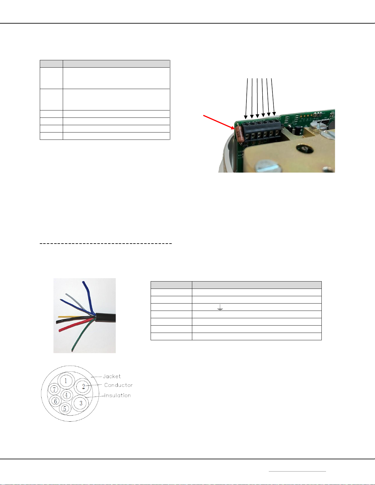
Note: if the sensing resistor R66 is removed (for 1-5 V input signals), we recommend placing a 10K
resistor between signal and signal GND.
Predetermined signal loss position DIP 9: ON
With DIP 9 in the on position, the actuator will move to a predetermined position when the signal is
lost (i.e.: if the signal falls below 2.80 mA or 0.700 V).
Setting of the predetermined signal loss position:
a.- turn DIP 9 to the “off” position
b.- re-zero the actuator by sending and holding an input signal between
2.80 and 4.16 mA (0.700 and 1.04 V) wait until the device is re-zeroed, (i.e.: valve is closed)
c.- by varying the input signal, move the actuator to the position that is going to be the
predetermined signal loss position.
d.- switch DIP 9 to the “on” position. The current actuator position will be saved as the default
signal loss position. (The default signal position is an absolute actuator position, not a signal
value.)
3. Re-zeroing the actuator and initiating calibration routine:
The actuator will re-zero when the input signal is between 2.80 and 4.16 mA (0.700V and 1.04 V). It
will turn clockwise until the actuator has reached the fully closed position of the valve.
If the valve is removed for any reason, the calibration routine must be initiated on the
actuator manually. This is done by toggling DIP 12 (switch position, then back to the original
position) while the actuator is powered. This will prevent damage to the valve.
If you need to re-zero in the opposite direction (i.e.: for pressure regulators, which typically go to
the “top” fully open position at 4 mA) change the setting of DIP 12 and cycle power.
4. Feedback calibration: [RCx-AC-xxxAF model actuators only]
The current feedback will be calibrated from the factory.
To re-calibrate the feedback:
a.- Turn off the actuator and disconnect the feedback and input signals. If possible, remove the
actuator from the valve.
b.- Connect the feedback signal to the signal input. Also connect the power and signal grounds.
c.- Power up the actuator with this “signal loop-back” setup.
d.- Short SP1. It will automatically run a special routine to calibrate the feedback signal to the
signal input. The whole process takes about 1.5 seconds.
e.- Turn off the power and reconnect the actuator as normal.

User Manual RCx-AC-xxxAx-8.09
Page 11 of 17 www.hanbayinc.com | 1 800 315 4461
Rev.2021.11 hanbaysales@hanbayinc.com
Manual Override
The RCx-xxxAx actuator with manual override can also be certified for hazardous locations (CSA and/or
IECEX). The additional manual override gear case and handle has no effective ignition sources and can
therefore be used in all hazardous locations for which the actuator enclosure is certified for.
Operation of the manual override when the actuator is powered will be difficult as the actuator will try to
maintain the valve in the position it has been commanded to.
Power should be removed if the valve is to be moved manually. If the valve is moved with
the manual override when its power is turned off, it will lose its position, and it will need
to be re-zeroed (as described in the Signal Loss and Calibration section).
Troubleshooting
Upon noticing a problem, your first step should almost always be to recalibrate the actuator by toggling DIP
12 while the actuator is powered. This alone can solve basic problems. See sub-section 3 above for more
details.
If the actuator does not move, try following these steps:
1) Re-calibrate the actuator. This will move the actuator regardless of what signal it is receiving.
2) A sticking valve may be the problem. Remove the valve from the actuator, and re-test the actuator.
3) Remove power. Re-check the wiring and the power/signal apparatus. Power actuator and re-calibrate.
If the problem persists, please call Hanbay for technical support.

User Manual RCx-AC-xxxAx-8.09
Page 12 of 17 www.hanbayinc.com | 1 800 315 4461
Rev.2021.11 hanbaysales@hanbayinc.com
EXPLOSION PROOF CERTIFICATIONS
Actuator model number: RCx-AC-BxxAx
IECEX
Standards & Editions:
IEC 60079-0:2017, 7th Edition
IEC 60079-1:2014, 7th Edition
*Serial number will be engraved on the lid.
CSA
Standards:
Class I, Div 1, Groups B, C, D (T6)
Class II, Groups E, F, G (T6)
CAN/CSA Std. C22.2 No. 0-M91 (R2001)
CSA Std C22.2 No. 25-1966 Locations
CSA Std C22.2 No. 30-M1986 Locations
UL 1203-2006
Lid engraving with CSA & IECEX certifications.

User Manual RCx-AC-xxxAx-8.09
Page 17 of 17 www.hanbayinc.com | 1 800 315 4461
Rev.2021.11 hanbaysales@hanbayinc.com
LABEL BREAKDOWN
Actuator Supply Voltage
12-24 VDC @ 3.0 A or
110-240 VAC @ 1.5 A
Circuit Board Version
Ax-8.09
Dx-10.31
Dx-4.10 (Obsolete since 2019)
Px-10.3
Actuator Part Number
Refer to part number
breakdown for available
options.
Ex-proof Certification
Info on ex-proof ratings
and installation
instructions.
Actuator Serial Number
This serial number is unique
for each individual unit and
is directly tied to your
order/invoice number.
Firmware Version
AF-1.05 MM = Multiturn
AB-1.05 MML = Multiturn Low Torque
AS-1.05 MMUL = Multiturn Extra Low Torque
QM = Quarter turn
QM97 = Quarter turn 97°
DT-2.01
DC-2.01
DT-4.06 (Obsolete since 2019)
M-Dx V2.31
Table of contents
Other Hanbay Camera Accessories manuals
Popular Camera Accessories manuals by other brands

Sanyo
Sanyo UR18650V Specifications

Regal Electro
Regal Electro VALEN Installation and operating instructions

Marshall Amplification
Marshall Amplification CV6XX-HFH user manual

Axis
Axis T91A52 installation guide

Nauticam
Nauticam NA-Z9 user manual

True blue power
True blue power TB17 Series Installation manual and operating instructions