HANBAY Inc User Manual RDx-B-xxxDT-10.31 Battery Fail Safe
Page 6 of 8 www.hanbayinc.com
Rev. 1 2019 1 800 315 4461
hanbaysales@hanbayinc.com
Appendix
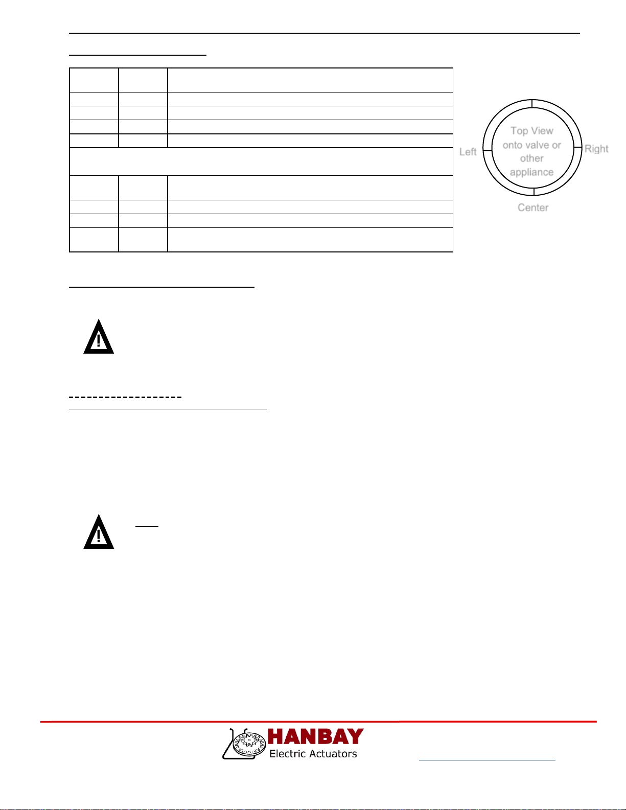
Calibration
The center position calibration routine can be initiated by switching DiP9 momentarily “on” then “off”. This will cause
the actuator to go through a series of movements to determine the proper center position. This function is useful if
the actuators output gear gets manually rotated while the actuator is powered down and can’t properly realign to the
center by itself.
Troubleshooting:
Upon noticing a problem, your first step should almost always be to recalibrate the actuator by switching DiP 9 on
then off, all while the actuator is powered. This alone can solve basic problems. See section 3 on this page for more
details.
If the actuator does not move, try following these steps:
1) Re-calibrate the actuator. This will move the actuator regardless of what signal it is receiving.
2) A sticking valve may be the problem. Remove the valve from the actuator, and re-test the actuator.
3) Remove power. Re-check the wiring and the power/signal apparatus. Power actuator, and re-calibrate. If
the problem persists, please call Hanbay for technical support.
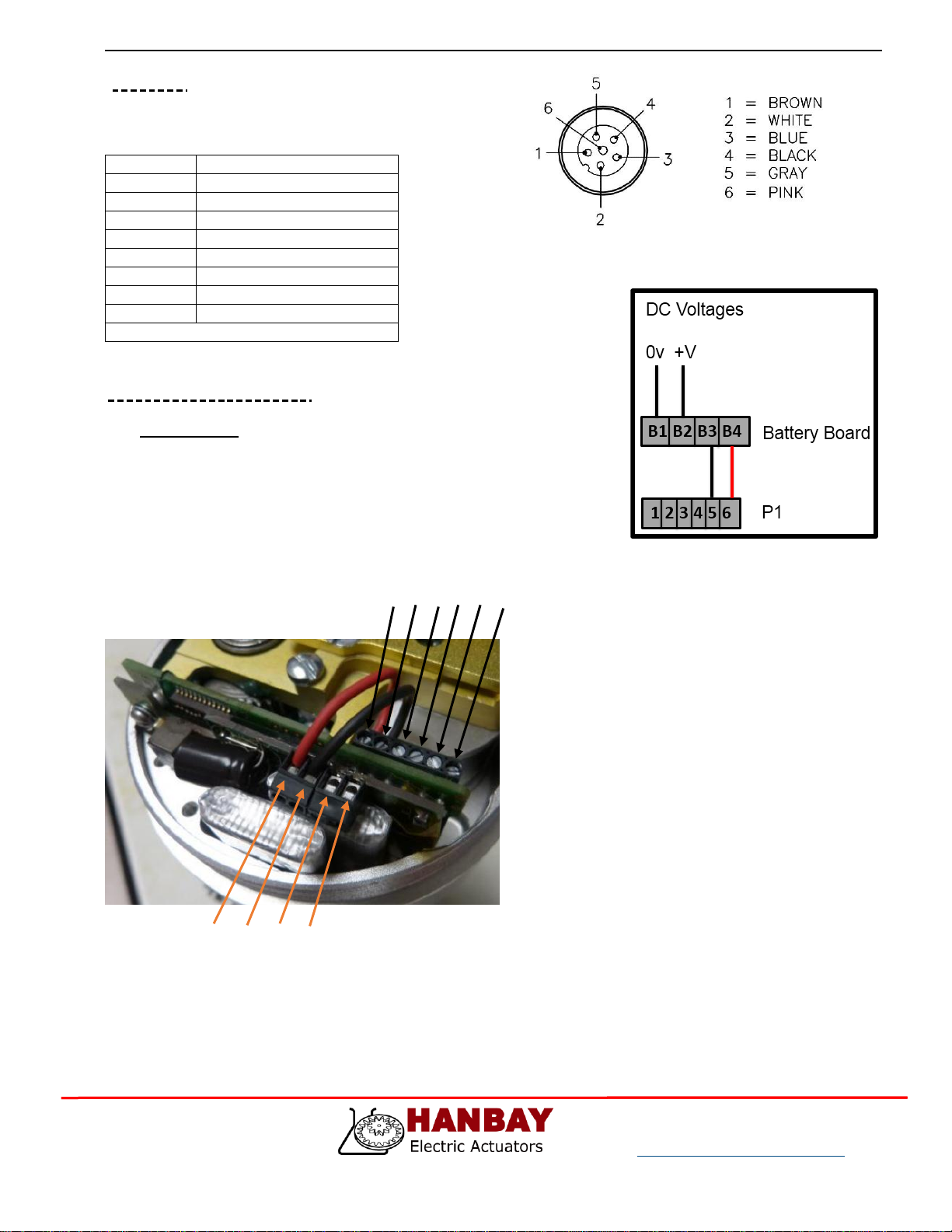
Battery Fail Safe Function:
In the event of a loss of power or signal, the battery will maintain power to the P1 processor and trigger the actuator
to move the valve to it’s designated fail-safe position, using power from the battery.
The TTL outputs will indicate the position of the valve, as in normal operation.
Once the valve has reached it’s fail-safe position, and after 25 seconds, the P1 processor will go into sleep mode to
preserve the battery life.
The actuator will not respond to commands until the power supply is restored.
The battery will maintain a charge for up to 2 months without power being applied.
The fail-safe actuation can be performed for 30 cycles on the charge available in the battery.
During normal operation, from totally discharged, the batteries will take 2 hours to re-charge.
If in a critical fail-safe application, the fail-safe function should be tested monthly.