HANKISON Filter Monitor User manual

1
7610.718.14 4/02
FILTER
MONITOR
INSTRUCTION MANUAL
SERVICE DEPARTMENT: (724) 746-1100
Introduction
The Filter Monitor continuously monitors the differential
pressure (pressure drop) across a filter and alerts the
operator of the need for element replacement when
any of three operating criteria are met:
1. Maximum elapsed time (service interval) before
change-out - operator alerted when user selected
time period elapses.
2. Maximum allowable differential pressure - operator
alerted when user selected maximum differential
pressure occurs.
3. Intelligence - operator alerted when the optimum time
to replace the element(s) has occurred. The Monitor
calculates this using the element type, the initial charac-
teristic pressure drop and historical pressure drop data.
Grade 9 3 0.21 0.20 B
Grade 7 4 0.28 0.28 C
Grade 6 4 0.28 0.28 D
Grade 5 5 0.35 0.34 E
Grade 3 6 0.42 0.41 F
Grade 1 3 0.21 0.20 G
Recommended Settings for HF Series Filters
1. Maximum time before element replacement: Grades 9, 7, 6, 5, 3, - 12 MONTHS;
Grades 1 - 6 MONTHS;
2. Maximum pressure differential:
Programming Instructions
(Short version - for complete instructions see page 3)
1. To begin programming, press and hold ENTER button
for 3 seconds.
2. Press and hold the scroll button to input maximum
service interval (1 to 15 months) - press ENTER.
3. Press and hold the scroll button to select pressure unit
of measure (KG/CM2,PSI, or BAR). - press ENTER.
4. Press and hold the scroll button to input maximum
pressure drop (0.01 to 1.00 KG/CM2 or BAR; 0.1 to
15 PSI) Use Left Shift and Right Shift buttons to select
advance rate (e.g. by ones, tenths, or hundredths) -
press ENTER.
5. Press and hold the scroll button to select the element
letter type (see chart above) - press ENTER.
6. Select Initalize or Run mode.
Initalize - Scroll until initial pressure drop and run icons
are displayed. (To be selected during initial installation
and element charge out).
Run -Scroll until run icon only is displayed. (To be
selected if Monitor is reprogrammed without changing
the element).
7. Press ENTER to start program.
HF Series Setting Element
Grade psid kgf/cm2bar LetterType
INITIAL P ICON
SHIFT LEFT
BUTTON SHIFT RIGHT
BUTTON
SCROLL
BUTTON
ENTER
BUTTON
OPERATOR
ALERT LIGHT
(RED LED)
LIQUID
CRYSTAL
DISPLAY
RUN ICON

1.0 INSTALLATION
1.1 Operating conditions
Maximum operating pressure: 250 psig, 17.6 kgf/cm2,
17.2 bar
Maximum compressed air temperature: 180°F, 82°C
Minimum/maximum ambient temperature: 10/130°F,
-12/54°C
1.2 Mounting
A. Changing orientation on units with Monitor
installed
1. Remove Monitor mounting screw.
2. Lift Monitor and turn 180°.
Note: Make certain that connector to mounting block is
not disconnected.
3. Reinstall Monitor to mounting block with mounting
screw.
B. Retro-fitting bowl/head type housings
Make certain filter is depressurized before disassembly.
1. Remove existing differential pressure devices or port
plugs if installed.
2. Install mounting block on filter head using o-rings,
gaskets and transmission bolts supplied with Monitor.
NOTE: Torque bolts to 30 inch-pounds (3.4 N-m). Do not
over tighten.
IMPORTANT: Mount block so that raised rectangle is next to
the INLET (high pressure or upstream) side of filter.
Note: Enlarge opening in cap if necessary. A pattern for a
larger cutout is located on underside of cap.
3. Connect lead from Monitor to prongs in mounting
block.
IMPORTANT: Position connector so that legs on connector
are on same side as raised rectangle.
4. Mount Monitor on mounting block using mounting
screw provided.
NOTE: Monitor may be rotated 180°so that it faces forward
with filter flowing from left-to-right or right-to-left.
C. Pressure vessel type housings
Make certain filter is depressurized before disassembly.
1. If mounting hardware has not been previously
installed, remove inlet/outlet port plugs and install
fittings, tubing, couplings, and brackets using parts
from Mounting Kit.
2. Connect mounting block to couplings using o-rings
and transmission bolts supplied with Monitor.
NOTE: Torque bolts to 30 inch-pounds (3.4 N-m). Do not
over tighten.
IMPORTANT: Mount block so that raised rectangle is next to
the INLET (high pressure or upstream side) connection.
3. Connect lead from filter monitor to prongs in
mounting block.
IMPORTANT: Connect so that legs on connector are on same
side as raised rectangle.
4. Mount Monitor on mounting block using mounting
screw provided.
2.0 OPERATION
2.1 Display Legend
LED DISPLAY
1. Unit of measure selection - pressure - pounds per
square inch.
2. Unit of measure selection - pressure - kilograms per
square centimeter.
3. Unit of measure selection - pressure - bar.
MONITOR
OPTIONAL
FILTER
BRACKET
LEAD
CAP
LEAD
MOUNT WITH LEGS FACING
RAISED RECTANGLE
MOUNT WITH
RAISED RECTANGLE
ON INLET SIDE
IN
OUT
O-RINGS
MOUNTING
BLOCK
TRANSMISSON
BOLTS
ENLARGE OPENING
IF NECESSARY
MOUNTING SCREW
LEG
LEG
GASKETS
LEAD
MOUNT WITH LEGS FACING
RAISED RECTANGLE
MOUNT WITH
RAISED RECTANGLE
ON INLET SIDE
LEG
MOUNT TO VESSEL
AS SHOWN
OR REMOTELY TO WALL.
IN OUT
SHIFT LEFT
BUTTON SHIFT RIGHT
BUTTON
SCROLL
BUTTON
ENTER
BUTTON
OPERATOR
ALERT LIGHT
(RED LED)
LIQUID
CRYSTAL
DISPLAY
1
234
567
9
101112131415
16
17
8
2
4. Indicates that predicted number of days until element
replacement required is being displayed or with 13 to
indicate element replacement required because maxi-
mum time has elapsed.
5. Displayed with 7 in program mode when inputting
maximum time before element replacement.
6. Indicates Monitor is in program mode.
7. Displayed in program mode when inputting maximum
time before element replacement.
8. Displayed in program mode with 10 when inputting
element type.
9. Displayed alone when Run mode selected or with 14 and
15 when Initialize mode selected.
10. Displayed in program mode with 8 when inputting
element type.
11. Displayed in program mode when inputting maximum
differential pressure or with 13 to indicate element
replacement required because maximum pressure
differential has occurred.
12. Indicates Monitor is processing data. Or with 13 to
indicate element replacement required due to intelli-
gence.
13. Indicates need for element replacement.
14. Indicates (displayed with 15) that initial characteristic
pressure drop is being displayed.
15. Indicates that current pressure drop is being displayed.
16. Indicates (displayed with 15) that average pressure drop
is being displayed.
17. Indicates need for battery replacement.
2.2 Batteries
A. Installation - Remove battery compartment cover
and install three AA, 1.5V batteries. Install in proper
orientation as noted in battery case. Re-install cover.
B. Life - Battery life is typically 15 months
operating the LCD display only with 7 days of
LED illumination thereafter. Red light will flash
and battery icon will show when batteries
require replacement.
C. Memory - Program settings and cumulative informa-
tion is retained during battery expiration and replace-
ment.
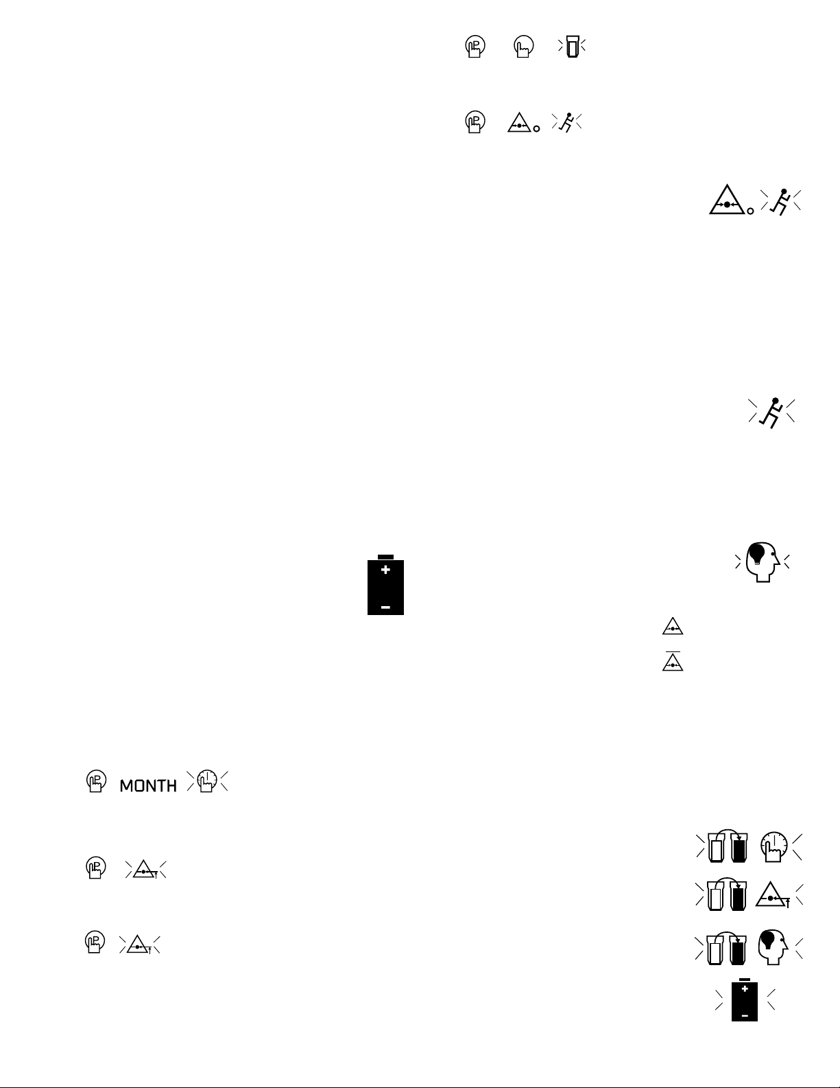
2.3 Programming
1. After batteries are installed, red LED light will glow
briefly; display will flash until unit is programmed.
2. Press and hold Enter button for 3 seconds to begin
programming.
3.
Select maximum elapsed time before element replace-
ment - press Scroll button to advance from 1 to 15
months.
4. Press Enter button to accept choice.
5.
Select unit of measure for pressure - use Scroll button
to choose between KG/CM2, PSI, or BAR
6. Press Enter button to accept choice.
7.
Select maximum allowable pressure drop - use Scroll
button to advance from 0.01 to 1.00 KG/CM2 or BAR; or
0.1 to 15 PSI. Use Shift buttons to change advance rate
(BAR and KG/CM2 -tenths or hundredths; PSI - tenths or
ones).
8. Press Enter button to accept choice.
9.
Input element type - use Scroll button to advance
from “A” to “H”. See chart on Page 1 for reference.
10. Press Enter button to accept choice.
11.
Select Initalize or Run modes.
Initialize
Use Initialize on initial start-up or after
replacing elements. To Select Initalize,
press Enter when pressure drop and
run Icons are displayed (Initialize symbol
shows). If Initalize is selected the program will ignore
the first 24 hours of operation to allow the element(s)
to achieve a steady state. After this period, pressure
drop measurements will be averaged over the next 144
hours to determine an initial characteristic pressure
drop. The differential pressure calculation used to
determine the optimum time for element replacement
uses this characteristic drop as the starting point.
After the initialization period, Monitor automatically
switches to the Run mode.
Run
To select Run, press Scroll button so that only
the run icon is displayed. If RUN is selected,
the monitor uses the previous initial charac-
teristic pressure drop as the reference. Use this mode if
the Monitor is re-programmed but the element is not
replaced.
12. Press Enter button to exit program mode and begin
operation.
2.4 Display
1. Run mode - in the run mode, Processing
icon flashes; indicating that the Monitor is
processing data.
2. Readouts - the display cycles through the following
readouts:
a. Current differential pressure.
b. Average differential pressure
over the past 24 hours.
c. Projected days until element replacement. When the
Monitor estimates that filter element replacement will
occur within 60 days, the days remaining will be
displayed. This allows time to have replacement
element(s) on hand.
3. Alarms
a. Indication of need for element replacement.
If any criteria for element replacement is met,
the red LED will flash.
1) Need for replacement based on
expiration of maximum time -
“0 days” displayed
2) Need for replacement based
on maximum pressure drop -
inputted maximum pressure
drop displayed.
3) Need for element replacement
based on intelligence (calculated
optimum time).
b. Need for battery replacement -
Battery Icon and red LED will flash.
3

4
WARRANTY
AUTHORIZATION FROM THE SERVICE DEPARTMENT IS NECESSARY BEFORE MATERIAL IS
RETURNED TO THE FACTORY OR IN-WARRANTY REPAIRS ARE MADE.
Division Of Hansen Inc.
Canonsburg, PA 15317-1700 U.S.A.
Tel 724-745-1555 Fax 724-745-6040
SERVICE DEPARTMENT: (724) 746-1100
The manufacturer warrants the product manufactured by it, when properly installed, operated, applied, and
maintained in accordance with procedures and recommendations outlined in manufacturer’s instruction manuals,
to be free from defects in material or workmanship for a period of one (1) year from date of shipment to the
buyer by the manufacturer or manufacturer’s authorized distributor provided such defect is discovered and
brought to the manufacturer’s attention within the aforesaid warranty period.
The manufacturer will repair or replace any product or part determined to be defective by the manufacturer
within the warranty period, provided such defect occurred in normal service and not as a result of misuse, abuse,
neglect or accident. Normal maintenance items requiring routine replacement are not warranted. The warranty
covers parts and labor for the warranty period unless otherwise specified. Repair or replacement shall be made at
the factory or the installation site, at the sole option of the manufacturer. Any service performed on the product
by anyone other than the manufacturer must first be authorized by the manufacturer.
Unauthorized service voids the warranty and any resulting charge or subsequent claim will not be paid. Products
repaired or replaced under warranty shall be warranted for the unexpired portion of the warranty applying to the
original product.
The foregoing is the exclusive remedy of any buyer of the manufacturer’s product. The maximum damages
liability of the manufacturer is the original purchase price of the product or part.
THE FOREGOING WARRANTY IS EXCLUSIVE AND IN LIEU OF ALL OTHER WARRANTIES, WHETHER WRITTEN, ORAL, OR
STATUTORY, AND IS EXPRESSLY IN LIEU OF THE IMPLIED WARRANTY OF MERCHANTABILITY AND THE IMPLIED WAR-
RANTY OF FITNESS FOR A PARTICULAR PURPOSE. THE MANUFACTURER SHALL NOT BE LIABLE FOR LOSS OR DAMAGE
BY REASON OF STRICT LIABILITY IN TORT OR ITS NEGLIGENCE IN WHATEVER MANNER INCLUDING DESIGN, MANUFAC-
TURE OR INSPECTION OF THE EQUIPMENT OR ITS FAILURE TO DISCOVER, REPORT, REPAIR, OR MODIFY LATENT
DEFECTS INHERENT THEREIN.
THE MANUFACTURER, HIS REPRESENTATIVE OR DISTRIBUTOR SHALL NOT BE LIABLE FOR LOSS OF USE OF THE PRODUCT
OR OTHER INCIDENTAL OR CONSEQUENTIAL COSTS, EXPENSES, OR DAMAGES INCURRED BY THE BUYER, WHETHER
ARISING FROM BREACH OF WARRANTY , NEGLIGENCE OR STRICT LIABILITY IN TORT.
The manufacturer does not warrant any product, part, material, component, or accessory manufactured by
others and sold or supplied in connection with the sale of manufacturer’s products.
hankisonintl.com
Table of contents
Popular Water Dispenser manuals by other brands

Philips
Philips Pure Taste WP3961 Specification sheet

CSI
CSI CM24 Installation & operation manual

Thermaltake
Thermaltake Pacific RL240 user manual

HydrogenX
HydrogenX Hydro6000x instruction manual

Hellenbrand
Hellenbrand Economical Water Conditioning System WaterMate... Specifications

Elkay
Elkay DSBWCT5G Installation, care & use manual


