Tier1 Elite Series User manual

IAPMO R & T Certied
against NSF/ANSI 44
and CSA B483.1
Owners Manual
Tier1 Elite Series
Water Softener
WS-ELITE-1054
WS-89HE-1054
1. This manual contains important maintenance procedures for the continued proper operation of
your unit.
2. Read all instructions carefully before operation.
3. Avoid pinched o-rings during installation by applying NSF certified lubricant to all seals (provided with install
kit).
4. This system is not intended for treating water that is microbiologically unsafe or of unknown quality without
adequate disinfection before or after the system.
1

Table of Contents
3
4
5
6
7
8
9
10
12
13
14
15
16
18
19
20
21
23
23
24
25
26
26
26
27
27
27
28
28
30
31
32
34
READ THIS PAGE FIRST
BEFORE STARTING INSTALLATION
HOW YOUR WATER CONDITIONER WORKS
SPECIFICATIONS
SPECIFICATION
SYSTEM DIMENSIONS
BRINE TANK DIMENSIONS
INSTALLATION
UNPACKING / INSPECTION OF TWIN TANK MODEL
CHECK VALVE TYPE AND VALVE SERIAL #
BEFORE INSTALLATION
PREPARATIONS
INSTALLATION STEPS
INSTALLING BRINE TANK
WATER SOFTENER INSTALLATION - UPFLOW
STARTUP & PROGRAMMING
PLUMBING SYSTEM CLEAN-UP
MAINTENANCE INSTRUCTIONS AND SCHEDULE
SERVICING
VALVE
TROUBLE SHOOTING GUIDE
REPLACEMENT
TIMER REPLACEMENT
PISTON AND/OR BRINE VALVE ASSEMBLYREPLACEMENT
METER ASSEMBLYREPLACEMENT
REPLACING THE BYPASS AND METER CABLE
CLEAN INJECTOR ASSEMBLY
REPLACE MOTOR
REPLACE MICROSWITCHES
CIRCUIT BOARD REPLACEMENT
REPLACE BRINE LINE FLOWCONTROL
REPLACE DRAIN LINE FLOWCONTROL
AFTER SERVICING
PARTS BREAKDOWN
PARTS
POWERHEAD / BYPASS
VALVE BODY
DLFC PART # FOR VALVE / BLFC PART # FOR VALVE
/INJECTOR PART # FOR 89 VALVE
MASTER PROGRAMMING
IMPORTANT WARRANTY AND MAINTENANCE INFORMATION 39
32
2

READ THIS PAGE FIRST
BEFORE STARTING INSTALLATION
INSTALL NOTES &
SAFETY MESSAGES
Watch for the following
messages in this manual:
NOTE
Do not remove or destroy
the serial number. It must be
referenced on request
for warranty repair or
replacement
CAUTION!
Disassembly while
under pressure can
result in flooding.
WARNING!
ELECTRICAL SHOCK
HAZARD! UNPLUG THE UNIT
BEFORE REMOVING THE
COVER OR ACCESSING ANY
INTERNAL CONTROL PARTS
NOTE: used to emphasize
installation, operation or
maintenance information
which is important but does
not present a hazard.
CAUTION: used when
failure to follow directions
could result in damage to
equipment or property.
WARNING: used to
indicate a hazard which
could cause injury or death if
ignored.
Read this manual thoroughly to become familiar with the
appliance and its capabilities before installing or operating
the new appliance. Failure to follow instructions in this
manual could result in personal injury or property damage.
This manual will also help you to get the most out of
your new appliance.
Installation must comply with all State &local regulations.
Check with your local public works department for plumbing
and sanitation codes. In the event the codes conflict with any
content in this manual the local codes should be followed.
Consult your licensed plumber for installation of this system.
WARNING!: Do not use water that is microbiologically
unsafe without adequate disinfection before or after this
system.
This appliance is designed to operate on pressures of 30
psi to 125 psi. If the water pressure is higher than the
maximum use a pressure reducing valve in the water supply
line to the device.
This appliance is capable of operating at temperatures
between 40°F and 110°F (4°C - 43°C). Do not use this
appliance on hot water supplies.
Avoid pinched o-rings during installation by applying
(provided with install kit) NSF certified lubricant to all seals.
It is not uncommon for sediment, precipitated iron or
hardness to be present in water supplies. Precipitated
minerals or sediments can cause damage to the seals and
piston. This is considered a harsh environment and the seals
and piston would not be covered by warranty stated or
otherwise.
It is recommended to regularly inspect and service the
control valve on an annual basis. Cleaning and or replacement
of piston, seals, and or spacers may be necessary depending
on how harsh the conditions are. An Annual Maintenance kit
is available for this purpose
3

4
Flow Rate Info:
At the stated service flow rates, the pressure drop
through these devices will not exceed 15 psig.
Peak flow rates are intended for intermittent use only
(10 minutes or less) and are for residential applications
only. Do not use peak flow rate for commercial
applications or for a continuous rate when treated
water supplies are geothermal heat pump, swimming
pool, etc.
For satisfactory operation, the pumping rate of the well
system must equal or exceed indicated backwash flow
rate.
This unit is equipped with an internal automatic bypass which will allow for untreated water to bypass the unit during a regeneration so the home is not without water
during this period. Regeneration time is factory set for 2:00 a.m. to minimize the chance of untreated water getting into your system during regeneration. Please try to avoid
use of water during this time period or adjust the regeneration time to a suitable time period when water use is at its minimum.
Even when operating a softener on water with less than the maximum of dissolved iron, regular cleanings should be performed. Clean every six months or more often if iron
appears in your conditioned water supply. Use resin bed cleaning compounds by carefully following the directions on the container.
Features & Terminology:
Feed Water Parameters:
Maximum Iron** = 2.0 ppm ferrous (clear water iron)
Maximum Hydrogen Sulde = 0.0 ppm
Maximum Manganese = .75 ppm
pH = 6.5 to 8.5 with no iron present or 6.5 to 7.3 with
iron present
**See Maintenance Section.
Precision Brining: Precision brining means that your conditioner calculates the exact
amount of brine required to regenerate saving up to 30% more salt.
When your conditioner regenerates it will display 2 numbers for capacity 1 will be
total capacity the other will be 70 % of capacity.The unit counts down to the end of
the 70% then calculates how much of the 30% you used (your reserve) it then adjusts
the brine amount accordingly and regenerates that evening.This feature means that
your capacity will always be different after every regeneration therefore maximizing
your salt use.
BRINE PRE-FILL% : This is the percentage of the water that will be added to the brine
tank after a regeneration. The default is 70%. The remaining amount of water will be
added just prior to the regeneration and will be proportional to the amount of
capacity left in the system.
Total Gallons and Remaining Gallons
Flow Rate: will read 0 unless water is currently being used
Date and Time
Remaining (Gallons): (gallons) remaining until next regeneration
Capacity Gallons: total capacity of system from last regeneration
Dealer contact information if available
After unlocking board you will have access to:
Date and Time
Hardness
Manual Regeneration
Dealer Information
Salt reminder
Main Menu**
**Main menu should only be accessed by a trained service provider or with appropriate
customer support guidance.
4

Upflow Softener Models
Model
System Capacity Grains Flow Rate RegenerationWater
Usage (Gallons) Mineral
Tank Size
Resin
Cu. Ft.
BrineTank /
Cabinet Size
Inches
Salt
Capacity
(Lbs)
Ship
Weight
(Lbs)
@ 10 lbs/
cu ft
@ 6 lbs/cu ft
(Factory Setting)
@ 3 lbs/
cu ft
Service
USGPM
Backwash
USGPM
CleanWater
(Factory Setting)
Problem
Water
89HE-844 30,000 25,000 15,000 10.0 2.0 43.4 64.3 9 x 48 1.00 18.1x34.7 120 110
89HE-1054 45,000 37,500 22,500 12.0 2.4 62.7 90.3 10 x 54 1.50 18.1x34.7 120141
89HE-1252 60,000 50,000 30,000 15.0 3.5 87.1 124.6 12 x 52 2.00 20.3 x 37.4 200 158
SPECIFICATION
Working Temperature:This unit must be
operated at temperatures between 40°F and
110°F (4°C - 43°C).
Working Pressure:This water softener
must be operated on pressures
between 30 psi to 125 psi. If the water
pressure is higher than 125 PSI, use a
pressure reducing valve in the water supply
line to the softener.
Voltage = 120V / 60 Hz
Pipe Size = 1”
• At the stated service flow rates, the
pressure drop through these devices will
not exceed 15 psig.
*Choose HIGH EFFICIENCY to minimize salt usage. Your system will
regenerate a little more often but your salt usage can be reduced by
20% compared to the STANDARD setting. Choose STANDARD when
you need to maximize your capacity but still operate the system with
good efficiency. Choose **IRON & MN if you have problem water
containing Iron, Manganese or hardness in excess of 50 gpg. The high
salt setting will be needed since these minerals are more difficult to
clean out of the resin bed. Note: A resin cleaner will also need to be
periodically added to the brine tank to insure proper operation.
Peak flow rates intended for intermittent use only (10
minutes or less) and are for residential applications only.
Do not use peak flow rate for commercial applications
or for a continuous rate when treated water supplies are
geothermal heat pump, swimming pool, etc.
For satisfactory operation, the pumping rate of the well
system must equal or exceed indicated backwash flow rate.
All units come with plastic bypass
**Maximum Iron = 2.0 ppm ferrous (clear water iron)
Maximum Hydrogen Sulfide = 0.0 ppm
Maximum Manganese = .75 ppm
pH = 6.5 to 8.5 with no iron present with iron present 6.5 -
7.5
CAUTION!
Do not use where the water is microbiologically
unsafe or with water of unknown quality without
adequate disinfection before or after the unit.
**NOTE
SET HARDNESS
This value is the maximum
compensated water hardness in
grains per gallon of the raw water
supply. It is used to calculate the
system capacity. If Ferrous Iron is
present add 4 gpg for every 1 ppm
of Ferrous Iron, 8 gpg for
Ferrous Manganese.
5
•Note: Inlet water which contains
measurable levels of chlorine or
chloramines may adversely affect
the resin life.

6
B
A
Models A (Inches) B (Inches)
63” 10"
SYSTEM DIMENSIONS
WS-ELITE-1054
6

Model Color Liquid Volume Tank Dimensions
(inches)
5 Pack Carton
Dimensions (inches)
Salt Capacity 5 Pack Carton
Shipping Weight
US Gal Liters L x W x H L x W x H Lbs Kg Lbs Kg
BrineTanks
BTR-70 Black 20.3 76.5 15.8 x 32.1 16.7 x 16.7 x 61.0 185.0 92.8 41.6 18.9
BTR-70 Blue 20.3 76.7 15.8 x 32.1 16.7 x 16.7 x 61.0 185.0 92.8 41.6 18.9
BTR-100 Vanilla 29.5 111.5 18.1 x 34.7 18.9 x 18.9 x 65.6 270.0 122.2 52.8 23.9
BTR-100 Black 29.5 111.5 18.1 x 34.7 18.9 x 18.9 x 65.6 270.0 122.2 52.8 23.9
BTR-100 Blue 29.5 111.5 18.1 x 34.7 18.9 x 18.9 x 65.6 270.0 122.2 52.8 23.9
BTR-145 Black 42.3 159.7 20.3 x 37.4 21.9 x 21.9 x 72.2 385.0 174.2 65.6 29.8
BTR-200 Grey 53.0 200.3 23.0 x 40.5 24.6 x 24.6 x 84 700.0 316.7 125.0 56.6
BTS-70 Black 19.0 71.8 13.1 x 13.1 x 34.7 14.4 x 14.4 x 62 175.0 92.8 48.8 22.1
BTS-70 Blue 19.0 71.8 13.1 x 13.1 x 34.7 14.4 x 14.4 x 62 175.0 92.8 48.8 22.1
BTS-100 Vanilla 25.0 94.5 15.0 x 15.0 x 34.7 16.6 x 16.7 x 61 230.0 104.1 54.4 24.7
BTS-100 Black 25.0 94.5 15.0 x 15.0 x 34.7 16.6 x 16.7 x 61 230.0 104.1 54.4 24.7
BTS-100 Blue 25.0 94.5 15.0 x 15.0 x 34.7 16.6 x 16.7 x 61 230.0 104.1 54.4 24.7
* All brine tanks come with salt grid, safety oat and brine well
BRINE TANK DIMENSIONS
7

,03257$17
3/($6((1685(7+($77$&+('
78%(67,))(1(5,6,16(57('
,1727+(%5,1(/,1(%()25(
7,*+7(1,1*
7+(187
Brine Tank
(Round or
Square)
Brine Tank
Tubing
Brine Well/
Safety Float
Brine Tank Lid
Grid (Round or Square)
Grid Legs (3 for
Round and 4 for
Square)
6. Brine Tank Assembly (Round Brine Tank Shown))
,03257$17
3/($6((1685(7+($77$&+('
78%(67,))(1(5,6,16(57('
,1727+(%5,1(/,1(%()25(
7,*+7(1,1*
7+(187
,03257$17
3/($6((1685(7+($77$&+('
78%(67,))(1(5,6,16(57('
,1727+(%5,1(/,1(%()25(
7,*+7(1,1*
7+(187
There are 7 Red clips. Please
check to make sure you
have all of them.
Distributor
Tube Inside
the Tank
Clips
1. Control Valve
2X 1”
Straight
Adapter
Bypass Tool
Drain Line
Gasket
2 X 1”
Elbow
Adapter
Transformer
Drain Hose Barb
Grease
Packet
Bypass with 4
Red Clips
2 x Clips
What is included in the box?
For Models 844, 1054 1252, you will expect the following:
1. Control Valve
2. Tank
3. Parts Box
4. Owners Manual
5. Drain Hose & Clamp
6. Brine Tank Assembly
Parts Box 3
UNPACKING / INSPECTION
Be sure to check the entire unit for any shipping damage or parts loss. Also note damage to the shipping cartons. Contact the transportation company for all damage and loss
claims. The manufacturer is not responsible for damages in transit.
Small parts, needed to install the Softener, are in a parts box. To avoid loss of the small parts, keep them in the parts bag until you are ready to use them.
2. Tank
8

12
CHECK VALVE SERIAL #
The right Sticker shows the serial # of the control valve. The middle Sticker is dataplate which provides information of Serial # and Date of Manufacture of complete system.
Both Serial # labels are important for troubleshooting.
Valve Serial #
Complete System Serial #
Item #
Desc
Date of Manufacture
Serial #
22018343 M 1 K 0001
PART NUMBER YEAR (2016) MONTH (JAN) DAY of MONTH (20) BATCH NUMBER
H = 2011 1 = JAN 1
I = 2012 2 = FEB 2
J = 2013 3 = MAR 3
K = 2014 4 = APR 4
L = 2015 5 = MAY 5
M = 2016 6 = JUN 6
N = 2017 7 = JUL 7
O = 2018 8 = AUG 8
P = 2019 9 = SEP 9
Q = 2020 A = OCT A = 10
B = NOV B = 11
C = DEC C = 12
D = 13
E = 14
F = 15
G = 16
H = 17
I = 18
J = 19
K = 20
L = 21
M = 22
N = 23
O = 24
P = 25
Q = 26
R = 27
S = 28
T = 29
U = 30
V = 31
Date Code Canature Valve
Valve Serial #:
9
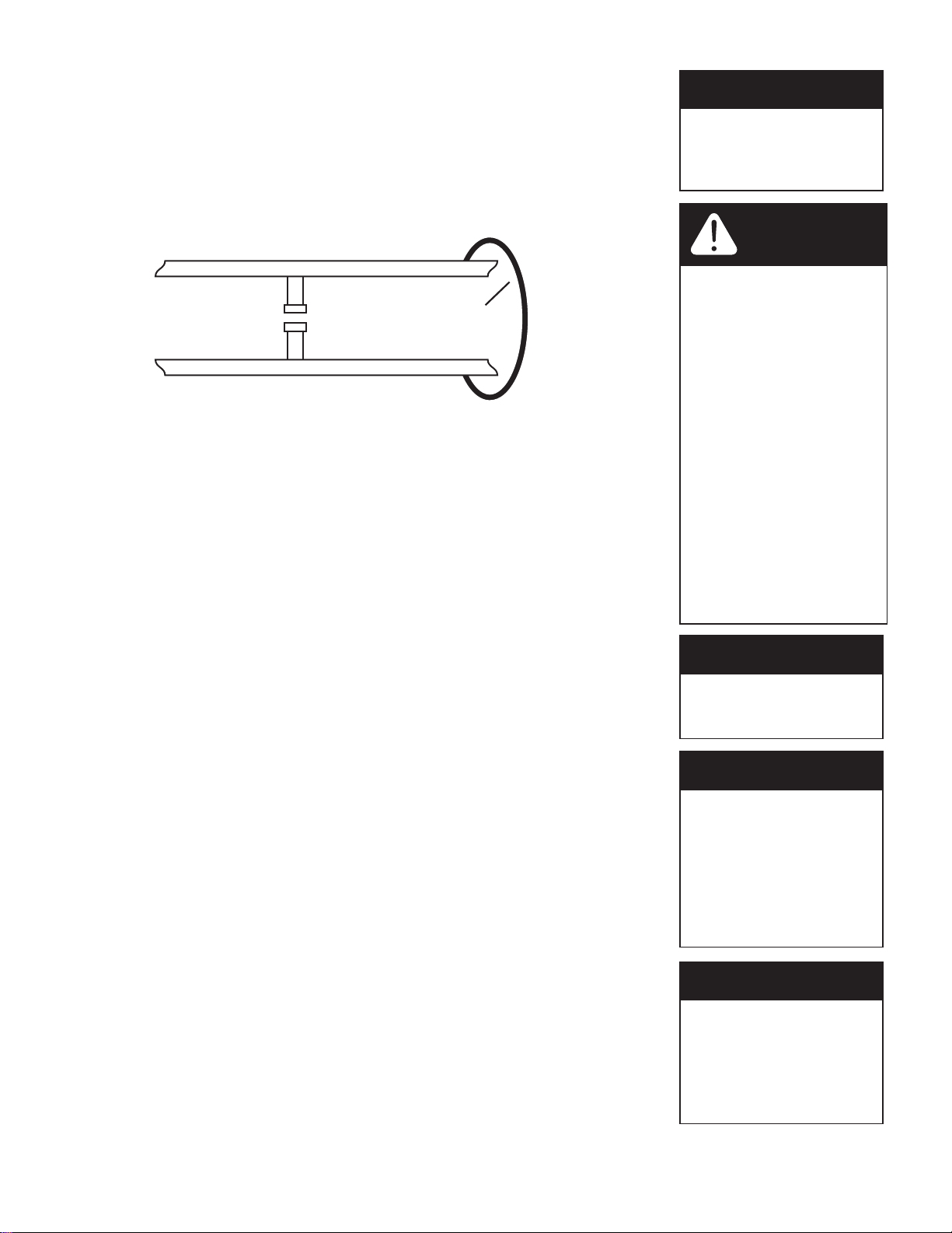
8QILOWHUHG:DWHU%\SDVV
/RRS&XW&DSSHG
*URXQG6WUDS5HTXLUHG%HFDXVH
RI%UHDNLQ&RQWLQXLW\
)LOWHUHG:DWHU/LQHLQ+RPH
Fig. 1.
BEFORE INSTALLATION
Make sure you have a copy of your most recent water test results. If your water has not been tested previously you can contact
your supplier of this product to obtain a water sample bottle to be sent to one of our facilities for a free analysis. It is important
that this product not be installed until you have this information.
In all cases where metal pipe was originally used and is later interrupted by poly pipe or the Noryl bypass valve or by physical
separation, an approved ground clamp with no less than #6 copper conductor must be used for continuity, to maintain proper
metallic pipe bonding.
Inspecting and Handling Your New System*
Inspect the equipment for any shipping damage. If damaged, notify the transportation company and request a damage
inspection. Damage to cartons should also be noted.
Handle the conditioner unit with care. Damage can result if it is dropped or set on sharp, uneven projections on the floor.
Do not turn the conditioner unit upside down.
To Insure this Product Functions Properly:
Your feed water line size to the unit must be a minimum of 3/4 inch with an operating pressure of no less than 30
psi and no more than 125 psi.
MECHANICAL:
Do not use petroleum based lubricants such as petroleum jelly, oils or hydrocarbon based lubricants.Use only 100% silicone
lubricants (grease packet provided in parts kit). All plastic connections should be hand tightened only. Teflon tape may be used
on connections that do not use an O-ring seal. Do not use pliers or pipe wrenches except where indicated by Nut shape (eg. pipe
adapters) All plumbing must be completed according to local codes. Soldering connections should be done before connecting
any pieces to the pipe as excessive heat can damage them.
Tools Required for Installation:
NOTE: We recommend installation only be completed by a competent installer or
plumbing professional to insure this product is installed in accordance with local
plumbing codes.
sTwo adjustable wrenches
sAdditional tools may be required if modification to home plumbing is required.
sPlastic inlet and outlet fittings are included with the conditioner. To maintain full valve flow, 3/4” or 1” pipes to and from
the conditioner fittings are recommended. You should maintain the same, or larger, pipe size as the water supply pipe, up
to the conditioner inlet and outlet.
sUse copper, brass, or PEX pipe and fittings.
sSome codes may also allow PVC plastic pipe.
sALWAYS install the included bypass valve, or 3 shut-off valves. Bypass valves let you turn off water to the conditioner for
repairs if needed, but still have water in the house pipes.
s5/8” OD drain line is needed for the valve drain.
NOTE
All government codes and
regulations governing the
installation of these devices
must be observed.
NOTE
If a severe loss in water
pressure is observed when
the conditioner unit is ini-
tially placed in service, the
conditioner tank may have
been laid on its side during
transit. If this occurs, back-
wash the conditioner to
“reclassify” the media.
*NOTE
Due to transportation
and climatic conditions all
connections including the
valve to the tank need to be
checked at time of
installation and tightened if
necessary.
NOTE
Check your local electrical
code for the correct clamp
and cable size.
CAUTION!
If the ground from the
electrical panel or breaker
box to the water meter or
underground copper pipe
is tied to the copper water
lines and these lines are cut
during installation of the No-
ryl bypass valve and/or poly
pipe, an approved grounding
strap must be used between
the two lines that have been
cut in order to maintain
continuity. The length of the
grounding strap will depend
upon the number of units
being installed and/or the
amount of copper pipe being
replaced with plastic pipe.
See Fig. 1.
10

14
d) Carefully position the valve over it and turn the valve into the threads in the fiberglass tank,
tightening securely into tank. Note: Ensure that the internal O-ring in the valve fits securely over the riser
tube. Silicone grease or other food grade lubricant may be applied to the O-ring to ease installation of the riser
tube.
d) Lube the bottomValve Orings with the grease supplied, Attach the Upper Cone. Unscrew the spill cap. Carefully
Slide the D-Tube inside the Valve and Screw theValve inside theTank such that the power cord doesnt
get caught between the valve and the tank.
O-ring
d
d
CAUTION: Make sure the power cord of the
valve doesnt get caught between the threads
Grease port Orings using
brush (not included) or
your finger (Make sure to
wear protective gloves)
D-Tube
Unscrew Spill Cap Attach
Cone
PREPARATIONS
CAUTION!
The unit should be
depressurized before
installing or replacing media
CAUTION!
Make sure that the
unit is de-pressurized
before conducting
this task.
CAUTION!
DO NOT use petro-
leum based lubricants
as they will cause
swelling of O-ring
seals.
11

Inlet
Outlet
Please notice the
inlet and outlet
tags on the valve
as shown here
to determine the
position of the
equipment
1” Straight
Adapters
Bypass
Drain Line
Brine Line
PREPARATIONS
Planning Your Installation
Select the location of your conditioner tank with care. Various conditions which contribute to proper location are as follows:
1. All installation procedures must conform to local and state or provincial plumbing codes.
2. Outside faucets used to water lawns and gardens should not supply untreated water, replace untreated water with feed water to the unit. If necessary to do this please
install check valve. A new water line is often required to be connected to supply untreated water to the inlet of the water conditioner and to the outside faucets.
3. Locate as close as possible to the water supply source.
4. Locate as close as possible to a floor or laundry tub drain.
5. Locate in correct relationship to other water conditioning equipment. if closer than 10 feet please install check valve in accordance with local plumbing codes.
6. Conditioners should be located in the supply line before the water heater. Temperatures above 110°F (43°C ) will cause damage to conditioners.
7. Do not install a conditioner or conditioner in a location where freezing temperatures occur. Freezing may cause permanent damage to this type of equipment and will void
the factory warranty.
8. Allow sufficient space around the unit for easy servicing.
9. Keep the conditioner out of direct sunlight. The sun’’s heat may soften and distort plastic parts.
2. Make sure the bypass is attached well to the control valve. Connect the straight or elbow connectors to the bypass with red clips. Connect the inlet and outlet of the water
conditioner to the plumbing of the house.The control valve must not be submitted to temperatures above 43°C (110°F).When sweat ttings are used, to avoid damaging
the control valve, solder the threaded copper adapters to the copper pipe and then, usingTeon tape, screw the assembly into the bypass valve.
Do not use pipe thread compound as it may attack the material in the valve body.
3. ApplyTeon Tape and Orings to the ttings
4. Connect Conditioner to the house plumbing. Any solder joints near the valve must be done before connecting any piping to the valve. Always leave at least 6”(152 mm)
between the valve and joints when soldering pipes that are connected to the valve. Failure to do this could cause damage to the valve.
5. Drain Line connection: Attach 1/2”ID, 5/8”OD drain hose to the hose barb and tighten securely with a hose clamp. Run the drain line to a oor drain or a laundry drain.
Complete any necessary plumbing.
1. Determine the best location for your water conditioner, bearing in mind the location of your water supply lines, drain line and 120 volt AC electrical outlet. Subjecting the
conditioner to freezing or temperatures above 43°C (110°F) will void the warranty.
INSTALLATION STEPS
12

16
INSTALLATION STEPS
NOTE
Before starting installation,
read page 18, Plumbing
System Clean-Up, for
instructions on some
procedures that may need
to be performed first.
6. *Using the Allen Key (included), place the unit in the bypass position. Slowly turn on the main water supply. At the nearest cold treated water tap nearby remove
the faucet screen, open the faucet and let water run a few minutes or until the system is free of any air or foreign material resulting from the plumbing work.
7. Make sure there are no leaks in the plumbing system before proceeding. Close the water tap when water runs clean.
8. Open the brine tank salt lid and add water until there is approximately 3”(75 mm) of water in the tank. Do not add salt to the brine tank at this time.
*Automatic Water Bypass
The regeneration cycle lasts approximately 1.5 hours to 3.0 hours depending on the specic model, after which treated water service will be restored. During regeneration,
untreated water is automatically bypassed for use in the household. Hot water should be used as little as possible during this time to prevent hard water from lling the water
heater.
should be
IMPORTANT: This is why the automatic regeneration is set for sometime during the night and manual regenerations performed when little or no
water will be used in the household. See ‘STARTUP & PROGRAMMING’, pages 16 for more info on Regeneration Programming.
*Manual Water Bypass
In case of an emergency such as conditioner maintenance, you can isolate your water conditioner from the water supply using the bypass valve located at the back of the control.
In normal operation the bypass is open with the ON/OFF knobs in line with the INLET and OUTLET pipes.To isolate the conditioner, simply rotate the knobs clockwise (as indicated
by the word BYPASS and arrow) until they lock. You can use your water related xtures and appliances as the water supply is bypassing the conditioner . However, the water you
use will be hard.To resume treated service, open the bypass valve by rotating the knobs counterclockwise. Please make sure bypass knobs are completely open other-
wise the unconditioned water could bypass through the valve.
NOTE
If the plumbing system is
used as the ground leg of
the electric supply,
continuity should be
maintained by installing
ground straps around any
nonconductive plastic
piping used in installation.
- See page 15
Sample
Connection
Sample
Connection
SERVICE
BYPASS
Sample
Connection
Sample
Connection
SERVICE
BYPASS
BYPASS
13

Insert Sleeve inside the Tubing
Attaching Brine Tubing to the Brine Line
of the Valve
a) Attach the three brine grid legs to grid plate.The
legs will snap on to the tabs of the salt plate making
a“click”sound. For square brine tank there are four
legs.)
c) Drop the brine grid with brine well inside the
brine tank such that the nut tting faces the
hole on the brine tank. Then press the grid
evenly inside the brine tank until the brine grid
legs touches the bottom of the brine tank.
b) Insert the brine well assembly inside the grid
plate as well below.
d) Take the brine tube and insert the nut and plastic sleeve as
shown below.
e) Insert the tube in the oat assembly elbow and hand tighten
the nut. In many cases the brine line already come installed
from the factory. Leave the other end of the brine line tube
inside the brine tank
f)For installation of brine tank at the installation site, pull the
other end of the brine tube from the hole on the brine tank.
The completed assembly is shown below.
The hole in
the brine tank
should line up
with the brine
line as shown
for round and
square brine
tank.
IMPORTANT:
IN ROUND
BRINE TANK, IT
IS IMPORTANT
TO ALIGN THE
HANDLE TO
THE BRINE
WELL AS
SHOWN
Insert Sleeve
INSTALLING BRINE TANK*
14

18
Optional
Overow
Assembly
Brine Valve
Connector Detail
AC120V/10A
Current Protect Socket Brine Elbow
Assembly
Water Pipe Outlet
Main tank
5/8”Drain Line
Bypass assembly
5/8”Overow Line
Floor drain
Optional
Pipes Fixed
Structure
Drain Elbow
Assembly
Outlet
Brine Tank
3/8”Brine Tube
Inlet
Water Pipe Inlet
Upflow Water Softener Installation
Outlet
NOTICE - THERE ARE INLET
AND OUTLET LABELS
ON THE VALVE. PLEASE
MAKE SURE TO PLUMB AS
SHOWN HERE
Inlet
*NOTE
Check local plumbing codes
in regards to requirements
for use of Check Valve or
back flow prevention or
vacuum breaker
Cold (Raw water)
Cold (Filtered water) Cold (Raw water)
Check Valve
Water Heater
Hot (Soft Water)
Upow Water Softener
Filter
InIn Out
Out
Cold (Soft Water)
T
o Outside Faucet
InOut
*
CAUTION!
Never insert drain line
directly into a drain, sewer line, or trap.
Always allow an air gap between the drain
line and the wastewater to prevent the
possibility of sewage being back-siphoned
into the conditioner.
NOTE
Waste connections or drain
outlet shall be designed and
constructed to provide for
connection to the sanitary
waste system through an
air-gap of 2 pipe diameters
or 1 inch (22 mm) whichever
is larger.
Connect Softener to the House Plumbing Any solder joints near the valve must be done before connecting any piping to the valve. Always leave at least 6”(152 mm)
between the valve and joints when soldering pipes that are connected to the valve. Failure to do this could cause damage to the valve.
WATER SOFTENER INSTALLATION
15

22
MENU
SET
MENU BUTTON
The function of this key is to
enter the level one program-
ming mode where the valve
settings can be adjusted.
SET BUTTON
This button has two functions.The rst is to initiate a manual
regeneration by holding the button for 3 or more seconds.The
second function is while in programming mode, pressing this key
allows the user to change the value of each setting.
UP / DOWN
These buttons are used to
increase or decrease the value
of the settings while in the
programming mode.
Key Pad Conguration
Hardness
025 GPG
Press [ ] To Cancel
Press [ ] To Conrm!
MENU
SET
MENU
SET
MENU
SET
Press MENU Key
5SEC To Unlock
Aug/30/2019
12:15AM
Backwash
10:00 Remain
1. The display will read “PRESS MENU KEY
3 SEC TO UNLOCK”.
2. After 3 seconds, the display will beep
confirming unlock.
3. Press and hold SET to start Manual
Regeneration process
4. The display will read time remaining.
ALLOW TO FINISH FULL CYCLE.
STARTUP & PROGRAMMING
The control valve is controlled with simple, user-friendly electronics displayed
on an LCD screen.When power is connected, the screen will show the following
information in sequence:
1. Date &Time
2. Regeneration Days (Time
interval between backwashes)
. Remaining Days (days left before
backwash begins)
4. RegenerationTime (Time of day
when backwash starts)
5. Last Regeneration Date (Last
date when system backwashed)
. Current Flow Rate (GPM) (ow
rate of water being currently used)
7. Peak Flow Rate (GPM) (Max
recorded ow rate of the water)
STEP 1. Connect the Transformer to the Valve
Plug the 12-volt transformer into a 120 VAC 60 Hz outlet.
BRINE TANK MODEL – Water to be Added at theTime of Installation:
BTR-100 (18.1”x 34.7”) - 2.5 US Gallons
STEP 2. Add Water to Brine Tank
Open the brine tank /cabinet salt lid and add water as per the info below.
Do not add salt to the brine tank at this time.
Please call Tier1 before attempting to change any Level 2 values as this can affect the performance of your unit. (See
page 40 for Level 2 Programming)
STEP 3. Manually Regenerate the Valve
3a. Open the inlet on the bypass valve slowly and allow water to enter the unit. (The outlet of the bypass should remain closed to prevent any nes or debris from entering the
plumbing system. Allow all air to escape from the unit before turning the water on fully then allow water to run until the drain water appears to be clear of any nes or
color.
3b. Plug in the valve. Allow the valve to continue its cycles until complete and back in service. Allow the valve to stay in each position for 2 - 3 minutes to purge air from the
system and the valve. Failure to properly purge the system may result in unsatisfactory performance.This process can be performed more than once if necessary to purge
air and color or nes from the system before nishing start up. Once the system is purged properly you can open the outlet of the bypass valve. Because your plumbing
system has been disturbed it is advisable to remove screens from faucets and ush all lines until clear. See Plumbing System Clean-Up on page 19.
STEP 4. PROGRAMMING YOUR CONDITIONER
This unit is factory set for the correct size, you are required to program the date, and the correct hardness setting.
16

MENU
SET
MENU
SET
MENU SET
Key Pad Conguration
MENU This function is to enter the basic set up information required at the
time of installation.
SET This function is to initiate an immediate or delayed manual
regeneration.
DOWN / Increase or decrease the value of the settings while in the
UP programming mode.
MENU
SET
Date and Time
Hardness
Manual Regen.
Dealer Information
Salt Reminder
Main Menu
Auto On
Regen. Now?
Regen. Tonight?
Press To Cancel
Press To Conrm
Brine Drawing ...
Any Key 3s To Next
103:59
68%
Backwashing ...
Any Key 3s To Next
13:59
88%
Rinsing ...
Any Key 3s To Next
12:09
90%
Relling ...
Any Key 3s To Next
03:59
98%
Relling ...
Any Key 3s To Next
Date and Time
Hardness
Manual Regen.
Dealer Information
Salt Reminder
Main Menu
QUALITY WATER
666 3 AVE
CHIGAGO IL
TEL 12345678
Setting Complete
Press To Return
Date and Time
Hardness
Manual Regen.
Dealer Information
Salt Reminder
Main Menu
= Date and Time =
17-Feb-2016, 12:25PM
Press To Cancel
Press To Conrm
Setting Complete
Press To Return
Standby
interface
Auto On
Auto On
Date and Time
Hardness
Manual Regen.
Dealer Information
Salt Reminder
Main Menu
ON
OFF
Auto On Dealer
information
input letter
by letter
4. Manually Regenerate the Valve (Continued)
4a. Open the inlet on the bypass valve slowly and allow water to enter the unit. (The outlet of the bypass should remain closed to prevent any nes or debris from entering the
plumbing system. Allow all air to escape from the unit before turning the water on fully then allow water to run until the drain water appears to be clear of any nes.
4b. Plug in the valve. Allow the valve to continue its cycles until complete and back in service. Do not manually shorten this cycle as it is critical to have the valve go through all
cycles normally to purge all air from the control valve for the upow injection system to work correctly.
4c. TheValve is already programmed from factory. Please set up date and time of day and feedwater hardness as shown below:
NOTE** All units are factory programmed for the correct size and regeneration cycle, alteration should only be done by a factory
trained technician or after consultation with one of our technical representatives if you have any questions please
call: 1-855-378-9116
STARTUP & PROGRAMMING (CONTINUED)
5. Power and Program Valve
Initial Manual Regen by pressing SET button.When in backwash cycle, do not skip the cycle and let all air from the tank escape.
After backwash cycle, the valve will advance to brine draw which needs to be skipped by pressing SET button.
The valve will now advance to RINSE CYCLE which can be skipped.Then valve will advance to rell cycle which should not be skipped.This cycle will let the air our of ejector system
of the valve.
17

24
Salt
Water
STARTUP & PROGRAMMING (CONTINUED)
*6 Add Salt to the Brine Tank/Cabinet
Put 88 lbs of crystal water conditioner salt in the brine tank. The unit will automatically
fill the water to the correct level when it regenerates. Start up and
programming
complete.
Unit is now
operational.
NOTE
NEW SOUNDS
You may notice new sounds as
your water conditioner
operates. The regeneration
cycle lasts approximately 1.5
hours to 3.0 hours depending
on the specific model. During
this time, will be able to hear
water running intermittently to
the drain, depending on
proximity of the unit to
sleeping area and time of
regeneration.
PLUMBING SYSTEM CLEAN-UP
The following procedures are guidelines only but have proven successful in most instances. Under no circumstances should any procedure outlined below be followed if contrary
to the appliance manufacturer’s instructions. Should there by any questions concerning the advisability of performing a procedure, it is strongly recommended the manufactur-
er’s authorized service outlet be consulted prior to performing the procedure.
Water Heater
If the water heater has been exposed to both iron and hardness for a long period of time, replacement of the heater tank maybe the only practical solution to prevent continued
staining originating from this source. After completing the installation of the conditioner, clean the water heater by following these instructions:
1. Shut o energy supply to water heater and close heater inlet water valve.
2. Drain hot water tank completely. Open inlet water valve allowing heater tank to be relled with iron-free water. Continue
ushing until water runs clear to drain.
3. If, after approximately 30 minutes ushing, water does NOT clear, terminate ushing operation. Rell hot water heater with
water and pour approximately 1/2 gallon of household bleach into top of heater tank. Allow bleach solution to stand in tank for
20 to 30 minutes. Flush tank.
Dishwasher
Consult owners’handbook and follow manufacturer’s instructions.
Toilet Flush Tanks
Prior to commencing installation of the conditioner system, pour 4 to 6 ounces of resin mineral cleaner Pro-Rust Out or or other suitable cleaner such as CLR that contains a mild
acid into ush tanks and bowls and let stand.When installation is completed, ush toilets several times with conditioned water. If stains or deposits return check that lines are
connected to treated water. Repeat procedure until clear. again until water is clear at drain.Turn energy supply on.
NOTE
If water does not clear in
approximately 10 minutes,
water heater should
probably be replaced.
18

Salt
Water
Service Schedule
The seals and spacers along with the piston assembly should be inspected/cleaned or replaced every year depending on the inlet water quality and water usage.
See inspection and replacement of Piston Assembly and Seal and Spacer Kit, page 23.
The injectors should be cleaned/inspected or replaced every year depending on the water quality and use. See Clean Injector Assembly, page 26.
The media should be replenished or replaced depending of inlet water quality and water consumption. Check with your water treatment expert on the media bed
change frequency.
Maintenance Kit (60010307) should be used for servicing control on an annual basis.The
maintenance kit consists of piston assembly, seals and spacers, injectors.
Maintenance of your new water conditioner requires very little time or eort but it is essential. Regular maintenance will ensure many years of ecient and trouble free operation.
FAILURE TO FOLLOW BASIC MAINTENANCE SCHEDULE WILL RESULT IN THE UNIT FAILING TO OPERATE PROPERLY AND VOID YOUR
WARRANTY.
CAUTION!
Liquid brine will irritate eyes,
skin and open wounds -
gently wash exposed area
with fresh water. Keep
children away from
your water conditioner.
Bridging
Humidity or the wrong type of salt may create a cavity between the water and the
salt.This action, known as“bridging”, prevents the brine solution from being made,
leading to your water supply being hard.
If you suspect salt bridging, carefully pound on the outside of the plastic brine tank
or pour some warm water over the salt to break up the bridge.This should always
be followed up by allowing the unit to use up any remaining salt and then thor-
oughly cleaning out the brine tank. Allow four hours to produce a brine solution,
then manually regenerate the conditioner .
MAINTENANCE INSTRUCTIONS AND SCHEDULE
Cleaning of your Brine / Salt tank
Salt tanks will build up sludge (undissolved salt) in the bottom of them that will continue to increase as time goes by. Every 2 - 3 years the salt tank should be cleaned out
completely and re started using the original start up instructions.
Never subject your conditioner to freezing, vacuum or to temperatures above 43°C (110°F).
Checking the Salt Level
Check the salt level monthly. Remove the lid from the cabinet or brine tank, make sure salt level is always above the brine level.
Add Salt to the Brine Tank
Put 40 kgs of crystal water conditioner salt in the brine tank.The unit will automatically ll the water to the correct level when it regenerates. Use only clean salt labeled for
water conditioner use, such as crystal, pellet, nugget, button or solar. The use of rock salt is discouraged because it contains insoluble silt and sand which build up in the brine
tank and can cause problems with the system’s operation. Add the salt directly to the tank, lling no higher than the top of the brine well.
NOTE :THE WATER LEVEL SHOULD BE BELOW THE SALT LEVEL ALL THE TIME
CAUTION!
Incorrect start up, water
above the salt level, (not
enough salt in tank) will both
effect the units capacity and
result in hardness slippage.
Should either of these situa-
tions happen or the unit fails
to regenerate for any other
reason please first correct
the problem. Then regen-
erate the unit manually 2
times in a row to restore the
reserve capacity and bring
the media bed back up to
specification.
19

28
1. Turn o water supply to conditioner :
a. If the conditioner installation has a 3 valve bypass system rst open the valve in the bypass line, then close the valves at the conditioner inlet & outlet.
b. If the conditioner has an integral bypass valve, put it in the bypass position.
c. If there is only a shut-o valve near the conditioner inlet, close it.
2. Relieve water pressure in the conditioner by stepping the control into the backwash position momentarily. Return the control to the In Service position.
3. Unplug Electrical Cord from outlet.
4. Disconnect drain line connection.
SERVICING THE VALVE
Before Servicing
CAUTION!
Disassembly while under
pressure can result in flooding.
Always follow these steps prior
to servicing the valve.
WARNING!
ELECTRICAL SHOCK
HAZARD! UNPLUG THE UNIT
BEFORE REMOVING THE
COVER OR ACCESSING ANY
INTERNAL CONTROL PARTS
20
This manual suits for next models
2
Table of contents
Other Tier1 Water Dispenser manuals

Tier1
Tier1 WS-165-132 Series User manual

Tier1
Tier1 WS-165-150-BLK User manual

Tier1
Tier1 WS-165-132-BLK User manual

Tier1
Tier1 WS-165-150 Series User manual

Tier1
Tier1 165 Series User manual

Tier1
Tier1 WS-165-150 Series User manual

Tier1
Tier1 RB-WS-165-132 User manual

Tier1
Tier1 H2-35 User manual

Tier1
Tier1 WH-HD-IRN-MG-948 User manual

Tier1
Tier1 RO5 User manual


