HANMEY IGN Series User manual

1GN SERIES
ROTARY CULTIVATOR OPERATOR’S MANUAL

2
CONTENTS
C H A P T E R ⅠM a i n t e c h n i c a l s p e c i f i c a t i o n s ………………………………………………………2
C H A P T E R ⅡB r i e f i n t r o d u c t i o n o n t h e s t r u c t u r e a n d t h e i r a d j u s t m e n t ………………………2
2 . 1 U n i v e r s a l c o u p l i n g a s s y … … … … … … … … … … … … … … … … … … … … … … … … … … … … 2
2 . 2 H e a d s t o c k … … … … … … … … … … … … … … … … … … … … … … … … … … … … … … … … … … … … 2
2.3 Central gearbox assy…………………………………………………………………………………3
2.4 Side gearbox assy … … … … … … … … … … … … … … … … … … … … … … … … … … … … … … … 3
2 . 5 R i g h t s i d e p l a t e a s s y … … … … … … … … … … … … … … … … … … … … … … … … … … … … … … … … 3
2.6 Cover assy………………………………………………………………………………………………3
2 . 7 C u l t i v a t o r s h a f t a s s y … … … … … … … … … … … … … … … … … … … … … … … … … … … … … … … … 3

3
2.8 Tailing bar………………………………………………………………………………………………4
C H A P T E R ⅢM e t h o d s o f o p e r a t i n g …………………………………………………………………5
3 . 1 I n s t a l l a t i o n o f h e a d s t o c k w i t h t h e m a i n b o d y … … … … … … … … … … … … … … … … … … … … … … 5
3.2 The methods of blade mounting………………………………………………………………………5
3 . 3 C o n n e c t i n g w i t h t h e t h r e e - p o i n t l i n k a g e o f t r a c t o r … … … … … … … … … … … … … … … … … … 5
3.4 Adjustment before working … … … … … … … … … … … … … … … … … … … … … … … … … … … 6
3 . 5 C u l t i v a t i n g r o u t e … … … … … … … … … … … … … … … … … … … … … … … … … … … … … … … … … … 6
3.6 Starting of the tiller………………………………………………………………………………………7
3 . 7 S e l e c t i n g o f f o r w a r d s p e e d … … … … … … … … … … … … … … … … … … … … … … … … … … … … … 7
3 . 8 O p e r a t i n g o f h e a d s t o c k … … … … … … … … … … … … … … … … … … … … … … … … … … … … … … 7
3 . 9 L o a d i n g t h e m a c h i n e … … … … … … … … … … … … … … … … … … … … … … … … … … … … … … 8
C H A P T E R ⅣMaintenance……………………………………………………………………………10
4.1 Daily maintance………………………………………………………………………………………10
4 . 2 S e a s o n m a i n t e n a n c e … … … … … … … … … … … … … … … … … … … … … … … … … … … … … … 1 0
4 . 3 Y e a r l y m a i n t e n a n c e … … … … … … … … … … … … … … … … … … … … … … … … … … … … … … 1 0
4 . 4 L u b r i c a t i o n s i t e s … … … … … … … … … … … … … … … … … … … … … … … … … … … … … … … … … 1 1
4 . 5 S t o r a g e … … … … … … … … … … … … … … … … … … … … … … … … … … … … … … … … … … … … 1 1
4 . 6 O p e r a t i n g a f t e r a t o r a g e … … … … … … … … … … … … … … … … … … … … … … … … … … … … … … 1 1
C H A P T E R ⅤC o m m o n b r e a k d o w n a n d i t s f i x i n g m e t h o d …………………………………12
C H A P T E R ⅥN o t e s f o r s a f e t y ………………………………………………………………………13
P a r t l i s t ………………………………………………………………………………………………………15
Please read this instruction carefully before using!
Please fill with the oil before operating!

4

5
Chapter ⅠMain technical specifications
These series rotary tiller, are driven by the power-take-off of tractor. It is a kind of excellent equipment and secondary tillage. It can match with 18.4-44.1 kw
(25-60HP) wheel-tractor, working on unplowed and plowed field. It has the characteristics of cold smaller on dry tillage, clay mashed and enough slurry on
paddy field, surface soil smooth, good coverage with weed and stubble, working depth uniform, efficiency high. It can get the results of multi-ply plowing by
one times tilling. It is suitable for plowing in dry field and paddy field in the area of producing wheat and rice.
These series rotary tiller have IGN-90, IGN-100, IGN-105, IGN-125, IGN-135, IGN-150, IGN-180 being adopted helical bevel gears meshing for main shift
gears in the gearbox, whole structure, whole cover and forced trailing bar, they are good rigidity, stable operation, low noise, high efficiency, low oil consume
and easy to maintain, etc. The ratio of breaking clod reaches above 95%.
The main parameters of IGN-125, IGN-135, IGN-150, IGN-180 are shown in the table below.
Model
IGN-125
IGN-135
IGN-150
IGN-180
Drive power (kw)
18.4-22.1
22.1-29.4
36.8-44.1
Tillage width (mm)
1245
1345
1495
1795
Tillage depth (mm)
dry field:120-140 paddy field:120-160
Blade type
Blade fixed on the blade disc rotor radius :R=230mm(special purpose)
Blade
amounts(piece)
30
30
36
42
Rotation speed of
blade shaft (rpm)
(PTO rotation
speed 540)
205
Productivity (ha/h)
Primary :0.2-0.29
Secondary:0.29-0.38
Primary :0.2-0.3
Secondary:0.3-0.4
Primary :0.25-0.35
Secondary:0.35-0.45
Primary :0.29-0.41
Secondary:0.41-0.53
Oil consume
(kg/ha)
Primary : 10-12 Secondary : 6-10

6
Joint manner
Standard three-point linkage
Overall
dimensions
(L×W×H)(mm)
1450×800×700
1550×800×700
1700×800×700
2000×800×700
Total quality (kg)
285
300
350
420
Quality of gear oil
(kg)
Gearbox≈2.5 side transmission box≈4
Application scope
Working in dry paddy fields and caked rice fields, rotating tillage and cutting off green
manure at 100kg/ha, shallow tillage in saline-alkaline land below average, tillage in
vegetable garden, land reclaiming, etc. The application scope in the moisture of soil is
wide. Commonly they can work as long as the matching tractors can operate.
Notes : ①Productivity measures according to 70% theory productivity.
7
Chapter ⅡBrief introduction on the structure and their adjustment
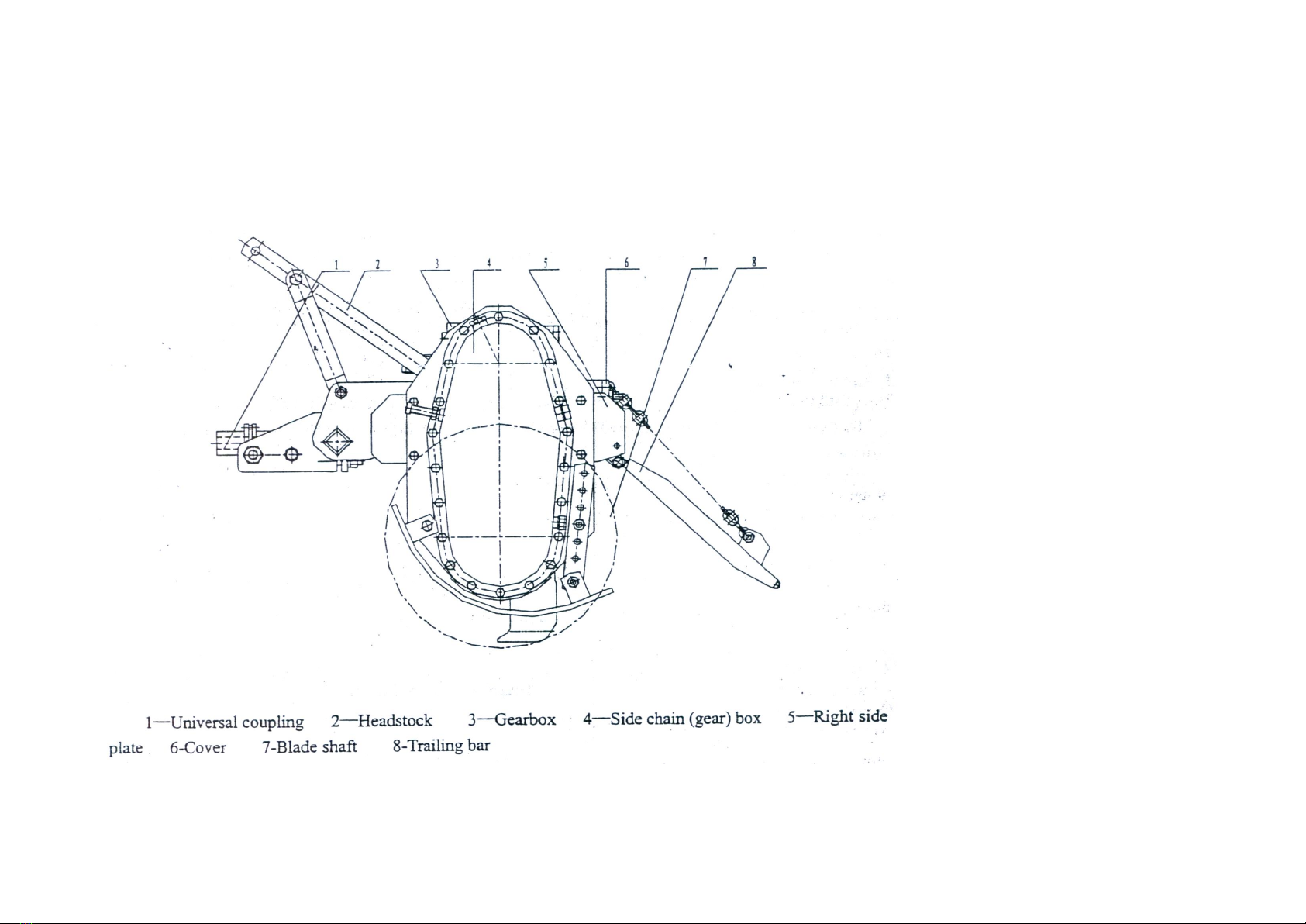
These catena rotary tillers are tillage equipment by means of the compound motion both of the rotation of the tractor going forward. It consists of universal
coupling, headstock, gearbox, side chain box (gearbox) are transmission sets. Blade and blade shaft are working parts. Headstock, the cover and trailing bar
are sets assistant. (Fig.1)

8
Fig.1 The side sketch of rotary tiller
2.1 Universal coupling assy
The universal coupling consists of universal joint head, universal joint head for male shaft, the universal joint head for female shaft and joint cross. There are
rings on the both ends of joint cross to avoid the movement of joint cross, and there is also a grease hole on the joint cross and the needle bearing can be
well lubricated if you inject grease into it frequently. The universal joint head for male shaft and the universal joint head for female shaft are sliding joint and it
can be pulled back and forth freely when the rotary tiller rises or falls. It must be noted that the interval between socket and shaft is in the shortest situation
but the socket and the shaft can not contact each other during operating, and if the interval between the socket and the shaft is in the biggest situation, the
overlap of socket and shaft must be longer or equal 1/2 length of the shaft.
2.2 Headstock
The upper hitch point on the headstock must be connected with the control link of the tractor and the lower coupling pin of headstock must be connected with
the tension link of the tractor to make the rotary tiller from the stable three-point hitch linkage.
2.3 Central gearbox assy
The central gearbox assy consists of gearbox, front cap, rear cap, first shaft, second shaft and a helical bevel gear pair that transmits the power to side chain
box, etc. And there is an oil hole for adding oil on the top of the gearbox. And there is a stopper for draining oil at the bottom of the gearbox. The helical bevel
gear is splined with the shaft. The gears are tightened with elastic collar, washer and locknut to prevent axial moving.
In using, the bearing clearance and the gear backlash will be changed because of wearing of bearings and gears, so you must adjust them (if necessary).
Adjustment of helical bevel gear backlash:
A proper backlash is the one of the condition for working normally. If the backlash is too small, result in the gear wearing rapidly or even biting one another. If
the backlash is to large, result in the gear making strong collision and loud noise.
Precaution:
Helical bevel gear backlash must be adjusted after the clearance of bearing on the first shaft has been adjusted. For retaining the clearance of bearing in
which have been adjusted, for pinion, the total thickness of adjusted shims of the front and the hind bearing seat on the first shaft must keep up. For example,
when moving the pinion forward, the decrease--the adjusted shims of the hind-bearing seat on the first shaft must added to the front bearing seat on the first
shaft, vice versa. For large helical bevel gear, when moving it rightward, you must decrease the shims of the bearing seat of the large bevel gear. In general,

9
just move the pinion forward when you do it.
Adjustment of the bearing axial clearance on the second shaft when the axial displacement was occurred very distinctly on the second shaft, you must adjust
it in time as following steps: First, loosen washer and screw down the locknut, then adjusts the displacement of the bearing on the second shaft until there
was no distinct axial movement and easy to rotate the shaft. Finally, lock the jam nut with the washer. This prevents the bearing from loosing.
2.4 Side gearbox assy
The side chain box consists of chain box, two chain wheels, chain, chain tension units, second shaft and shaft left side plate assy. Adjustment of the chain:
loosen and screw down the adjustable screw to adjust the tension of the chain, keep the right tension. In general, it can be pressed down 10mm at another
side of chain.
The side gearbox consists of side gearbox, three shaft and left side plate assy.
2.5 Right side plate assy
The right side plate assy consists of right side plate, right head of cultivator shaft, right side bearing and bearing seat.
2.6 Cover assy
A specific purpose of the cover is warding off clod, safeguarding the driver and still farther breaking the clod.
When rotary tiller is working, if the gap between the blade edge and the cover is too large, the cold would be thrown to the front of the cultivator shaft, so that
it will be cultivated once more, therefore the power of the tractor will be wasted; if the gap is too small, it is easy to congest. Recommend the normal gap is
30-45mm.
2.7 Cultivator shaft assy
The cultivator shaft assy consists of cultivator shaft, blade disc and blade.
2.8 Tailing bar
The function of the tailing bar is still farther breaking the clod and flatting the cultivator land. It was connected with cover. You can obtain different effect of land
surface by adjusting the height of the tailing bar. In general, if the soil is dry, to set lower, if the soil is wet, to set higher. When you remove the mud ande the
weed on the cultivator shaft, assemble the blades, long-distance transport; you can set the bar at the highest.

10

11
Chapter ⅢMethods of operating
3.1 Installation of headstock with the main body
Before being put in the container, the equipment is parted with the main body. The users refer to fig.2 simply to fix it on the main body with the bolts in the affix
pouch. Pay attention to fitting the spring washers on the bolts, and fastening them firmly.
3.2 The methods of blade mounting
To meet the requirement of agricultural technique, the blades are adopted different fixing methods, so that a variety of tillage effects can be gotten. Blades
should avoid mounting in reverse and making the back of the blades enter into soil. The parts will be damaged of overload.
The left-bent blades and the right-bent blades work in a stagger state on whole blade shaft. Only a blade enters into soil at the same time. This arrangement
is suitable to flat plowing. So the blade shaft operates stable; the surface of plowed field is smooth. To extend the application scope, every type of rotary tillers
has two sort of blade arrangement. Type 90 have 18 blades; type 100 and type 105 have 24 blades; type 125 and type 135 have 30 blades; type 150 have 36
blades; type 180 have 42 blades. Please take a strictly attention to mounting the blades according to the mark on the blade discs.
3.3 Connecting with the three-point linkage of tractor
The connecting way of rotary tiller with the tractor is three-point linkage. Its installing step is as follows:
1. Align the center of headstock by reversing the tractor, raise the link arm to appropriate height, reverse the tractor to make the link arm of tractor joint with
the left and right pin of rotary tiller.
2. First install the left lower linkage arm, then install right lower linkage arm, (because the leveling lift rod has screw that can be adjusted length.) finally inert
the pins.
3. Install the
upper linkage arm, and then insert the pin.
4. Mount the
universal coupling, and then insert the pins, poke the cotter pin.
It must be
taken attention to mounting order of the universal coupling.
Notes: it must
be given attention that the direction of universal coupling must be
correct in
installation if you use the universal coupling with female shaft.
(Fig.3, Fig.4)

12
3.4 Adjustment before working
1. Adjustment of horizontal level
Put it down to make the blade tips near to ground, observe that the height between the right and left blade tips and the ground is same or not. If not, it is
necessary that the right linkage arm of tractor be adjusted to level off the blade shaft, which ensures the uniformity of working depth.
2. Adjustment of longitudinal level
Fall the tiller to tillage depth desired, observe that universal coupling and PTO shaft are level or not. If the angle of universal coupling is too big, adjust the
control link to make it nearly level, which can maintain that universal coupling and the tiller work in the good condition.
3. Adjustment of rising height
Being forbidding that the tiller works at ±10°and above of the angle of universal coupling, turn at 30° and above, it is necessary to make the blade tips away
from the ground about 150mm-200mm. If require being risen higher when the tractor with the tiller passes through ruts and earth dyke or drive on the road,
the power driving the tiller must be cut off to prevent from danger. The position of the handle of the position control must be limited with the bolt if required.
4. Primary adjustment of working depth
Loosing the bolt on the lever limited the depth, adjust the position of the fixing hole, and then re-fix it, which the purpose is that the distance to the central
shaft be adjusted. Adjusted distance is 35mm per step.
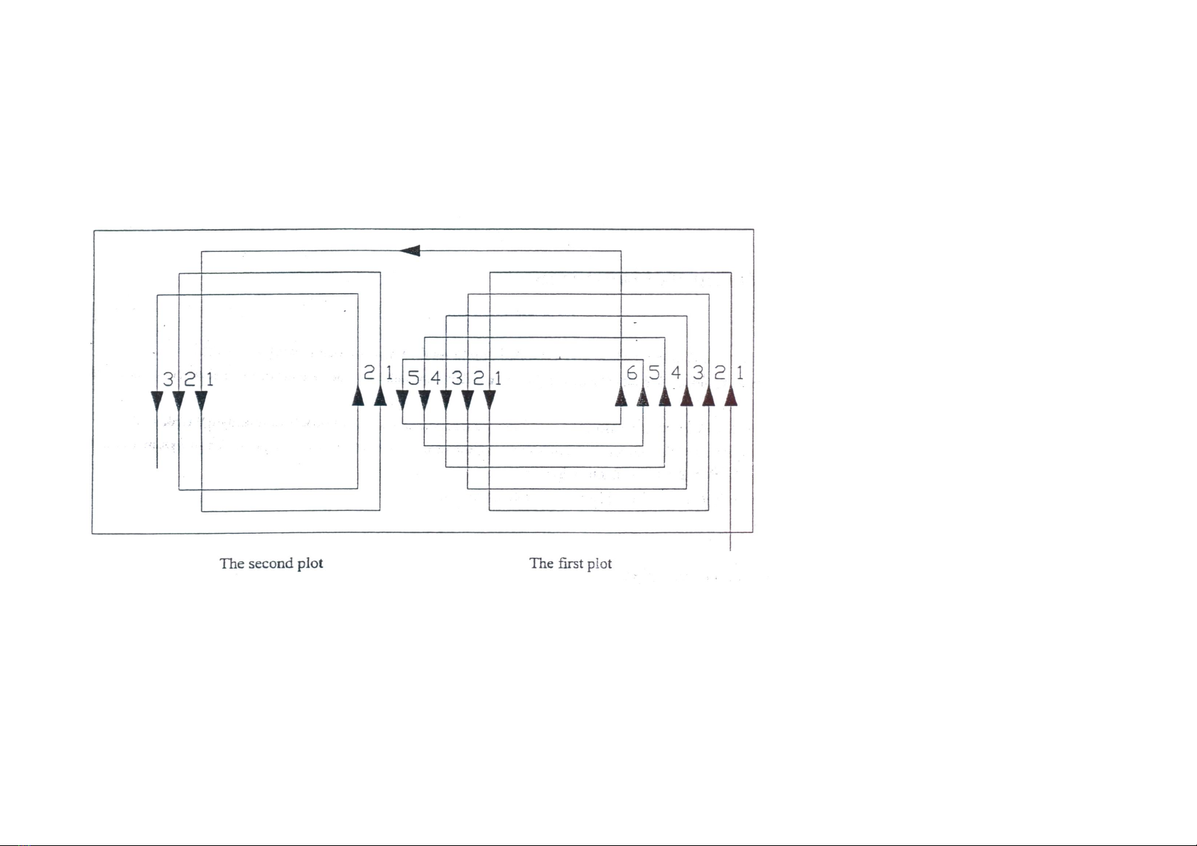
3.5 Cultivating route
When working in a piece of large land, in land plowing is adopted to reduce the empty time in turn land, to raise work efficiency. The width of the plot selected
is whole number multiple of the working width or near as possible, so as to decrease repeat tilling. The width of the plot is commonly 15m or so, if too wide,
13
the empty time in turn land will be longer, the efficiency be less, the repeat times of idle motion be more, tne mud depth be longer.
The flat tillage in the medium and small fields refer to in land plowing.
Fig.5 In land plowing
3.6 Starting of the tiller
First, filling with gear oil in the gearbox and the side chain box, injecting grease to the crosshead and the bearing seat of the blade shaft. Then check for the
looseness of all connecting bolts and nuts, if loosing, screwing it at once. If the crack and deforming are founding in the blades, they must be replaced.
Starting tractor: rise the tiller and the blade tip must be away from ground 150mm-200mm, and joint universal coupling, then run in 1-2minutes, gear the
operating gear position and increase the fuel throttle opening, control the leveling handle to make the tiller enter into the soil gradually until the normal tillage

14
depth at the same time.
3.7 Selecting of forward speed
The selecting principle of tiller forward speed: the tractor cannot overload constantly; the performance of breaking soil meet the needs of agriculture
requirement, furrow bottom and the soil surface are smooth. Not only be tillage quality ensured, but also the rated power of tractor be made good use of, and
the purpose of rising work efficiency must be attained.
Generally, rotary tilling directly: 2 km/h, harrowing: 5 km/h-7 km/h; if the unit draft of the soil is digger, can select lower gear; contrarily select higher gear;
when working in dry fields, select low gear; when working in paddy fields, select higher gear.
3.8 Operating of headstock
1. Forbid to use the draft control of tractor during rotary tilling, so that protecting the tiller.
2. Using position control when the tiller works. The handle of draft control must be put in the position marks “up”.
3. When the handle of position control moves forward, the tiller fall down; contrarily the tiller rise.
4. After the tiller reaching to required depth, using the position hand-wheel to block it, in favor of that the tiller falls the same depth every time.
5. The detail refer to the instruction of matching tractor.
3.9 Loading the machine
1. This machine can be loaded by fork lift.
2. The fork of fork lift must be put into the bottom of this machine.
3. When loading the machine, please take attention the balance of this machine.

15
Chapter ⅣMaintenance
To ensure that the tiller works properly, higher efficiency and prolonging the serve life, it is important that maintenance must be done properly.
4.1 Daily maintenance (after 10 hours operating)
1. Check, tighten up all of the joint bolts and nuts, tighten them up or replace them if necessary.
2. Check the lubricant oil in the gearbox and the side gear box, keep the oil level desired.
3. Check universal joint cross, pin, grease cup on the bearing seat, inject grease into the cup.
4. Check the blades to see if the blades are disable and their fasten bolts are loose, should replace or tighten them if necessary.
5. Check the tension of the side gears; adjust it if necessary.
4.2 Season maintenance (after one season operating)
Besides performing the proceeding of daily maintenance, the following must be done also:
1. Replace lubricating oil. It can be done in advance or delayed if necessary.
2. Check universal joint cross. If it is seriously worn, replace it.
3. Check the bearing in the twain ends of the blade shaft to see if turbid water enter it because of the faults of oil seals. Disassemble it to clean, replace the
oil seals and inject enough grease.
4. Check all bearings; adjust or replace them if necessary.
5. Check helical bevel gears; adjust them if necessary.
4.3 Yearly maintenance (after one year operating)
1. Remove all dust and filth away from the tiller.
2. Bleed out gear oil and disassemble the tiller to check on. If bearings be worn seriously or go wrong, it must be replaced; the parts must be cleaned before
assembled. Final, add new oil seals and inject enough grease.
3. Disassemble and clean the bearings and their seat of blade shaft, replace the oil seals and inject enough grease.
4. Disassemble and clean the universal joint cross assembly, and clean the roller pins of the universal joint, replace them if necessary.
5. Check the fastener and the cotter pins, etc. If the part is rusty or worn seriously, or the disable, it must be replaced.

16
6. Check the blades to see if there is crack, wear and tear on them, or loss. It must be replaced or added if necessary.
7. Check the blade holder, replace or repair them if necessary.
8. Repair the cover and the trailing bar.
9. The rotary tiller must be placed indoor as possible during it parks, and be raised to make the blade tips leave the ground. The blades and processing
surface revealed must smeared oil to prevent from rusty. The surface in which the paint broken off must be painted with the primitive colors to prevent
from rusty.
4.4 Lubrication sites (checked at the daily maintenance) see table 1
Table 1
Lubrication
Purpose
Oil check plug
Check the oil level of the gearbox and the side gearbox (injection
should continue until oil overflows out from the oil check hole)
Ventilate screw plug
Ventilation of the side gearbox
Grease cup of the joint
cross
Inject the grease into the joint cross (so that lubricate the roller needle
of the joint cross)
Grease cup of the
bearing seal on the
cultivator shaft
Inject the grease into the bearings and the oil seals of the cultivator
shaft (lubricate the bearings and the oil seals)
4.5 Storage
The machine inside and outside shall be cleaned carefully so as to avoid corrosion.
Don’t spray water on the rolling bearing if you clean the machine with high pressure sprayer.
Check and clean the universal joint, driving belt press roller, or replace them if they are not in good state.
Spread oil on all parts required.
Recoat the parts rubbed and damaged for anti corrosion.

17
Store the machine in a dry, level area. Support the frame with planks if require.
4.6 Operation After Storage
Before the machine is started up, check the following items regularly:
Check oil level and add it if not enough.
Check and tighten all screws and nuts;
Check the regulated state of the machine.
Check the blade state.
Check the air hole on the gearbox. If it is blocked, clean or open the hole with compressed air.
Don’t spread oil or grease on the driving belts. If there is oil or grease on the belts, wipe the belts, in case the belt sliding and wearing occur.

18
Chapter ⅤCommon breakdown and its fixing method
Breakdowns
Cause of breakdown
Removing method
Universal coupling
inclined too much
Rotary tiller failed horizontal level
Adjust the horizontal level of
the tiller
One side sway chain of tractor is too
short
Adjust the chain
Universal coupling
injured
Direction mistaken
Re-assemble correctly
Grease deficient
Rinse needle and inject grease
sufficiently
Angle of universal coupling is too big or
is gripped
Limit the rising position and
re-lock the position
Rotary tiller fallen down the soil sharply
Fall the tiller down the soil
smoothly
Noise in gearbox
The clearance between the two helical
bevel gears is too large
Adjust this clearance
Bearing injured
Replace bearing
Tooth of gear broken
Replace gear
Noise in side gear
box
Foreign matter dropped in gear box
Take foreign matter out of the
gear box
Bearing on the third shaft injured
Replace bearing
Bearing on the middle shaft injured
Replace bearing
Trouble rotation of
cultivator shaft
Gear or bearing injured or gripped
Replace gear or bearing
There was no clearance between the
two helical bevel gears
Adjust the clearance of the
helical bevel gear pair
Out of shape of left side plane
Correct side plane
Cultivator shaft crooked or out of shape
Correct or replace cultivator
shaft

19
Cultivator shaft twined with grass or hold
soil seriously
Clear away grass or soil
Blade slot injured
Blade run foul of stone so that it suffers
too much force
Clear away the stone from the
field
Blade assembled on opposite direction
so that it suffers too much force
Assemble the blades correctly
Rotary tiller fallen down the soil sharply
so that it suffers too much force
Fall the tiller down the soil
smoothly
Blades crooked or
broken
Blades run foul of stone
Replace the blades and clear
away the stones from the field
Doing plough when tractor turns a
corner in the field
Rise the tiller and do not
plough when the tractor turns a
corner in the field
Rotary tiller fallen down the hard ground
Fall the tiller down smoothly

20
Chapter ⅥNotes for safety
1. The operators must understand the operating characteristics and notes for safety.
2. Check the rotary tiller overall, it cannot be used until the technical condition is normal.
3. The angle of universal coupling is not more than ±10°when it is operating, and is not more than 30° when the tractor turns a corner in the field. You must
dismantle the universal coupling when long-distance transporting.
4. Do not engage the clutch behind the blades entering into the soil or fall down the rotary tiller sharply to prevent the transmission parts of the tractor and
rotary tiller form injured.
5. Do not plough when the tractor turns a corner in the field.
6. Do not plough when the tractor reverse.
7. Do not ride in tractor expect the driver when the rotary tiller is operating to prevent some one from dropping in rotary tiller.
8. Do not close the rotating parts when the machine is operating.
9. The machine must be stop and checked when hearing the abnormal noise in operating, and fix a breakdown.
10. The power from the PTO shaft must be cut off when checking the transmission parts, blades and gears etc. of rotary tiller. If the parts must be replaced, it
is necessary to stop the engine. Do not replace the parts when the engine is operating.
11. It is required that the driver should enhance his vigilance to cut off power to prevent from breakdown because the rotary tiller is a type of farm machine
driven by tractor.
This manual suits for next models
4
Table of contents


