Hanna edge User manual

Hanna Instruments reserves the right to modify the design, construction or appearance of its
products without advance notice.
MANEDGEEC 01/15
EC
®

2
Table of
Contents
Dear
Customer
Thank you for choosing a Hanna Instruments product.
Please read this instruction manual carefully before using this instrument. This
manual will provide you with the necessary information for correct use of this
instrument, as well as a precise idea of its versatility.
If you need additional technical information, do not hesitate to e-mail us at
representative near you at www.hannainst.com.
All rights are reserved. Reproduction in whole or in part is prohibited without the
written consent of the copyright owner, Hanna Instruments Inc., Woonsocket,
Rhode Island, 02895 , USA
Included...............................................................................................................................................3
Safety Measures..............................................................................................................................3
Description.........................................................................................................................................4
Diagram ..........................................................................................................................................4-8
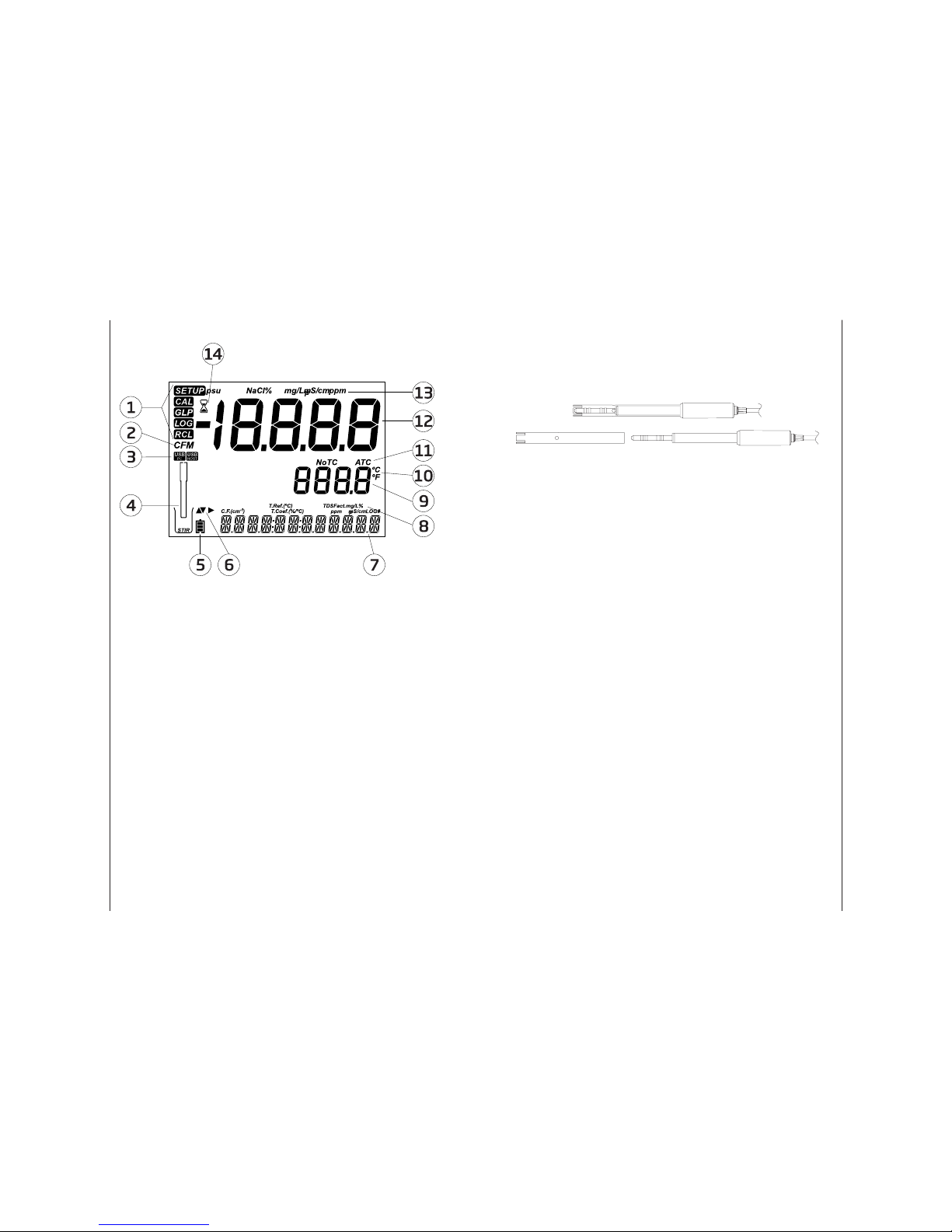
Product Diagram..................................................................................................................................................................4-5
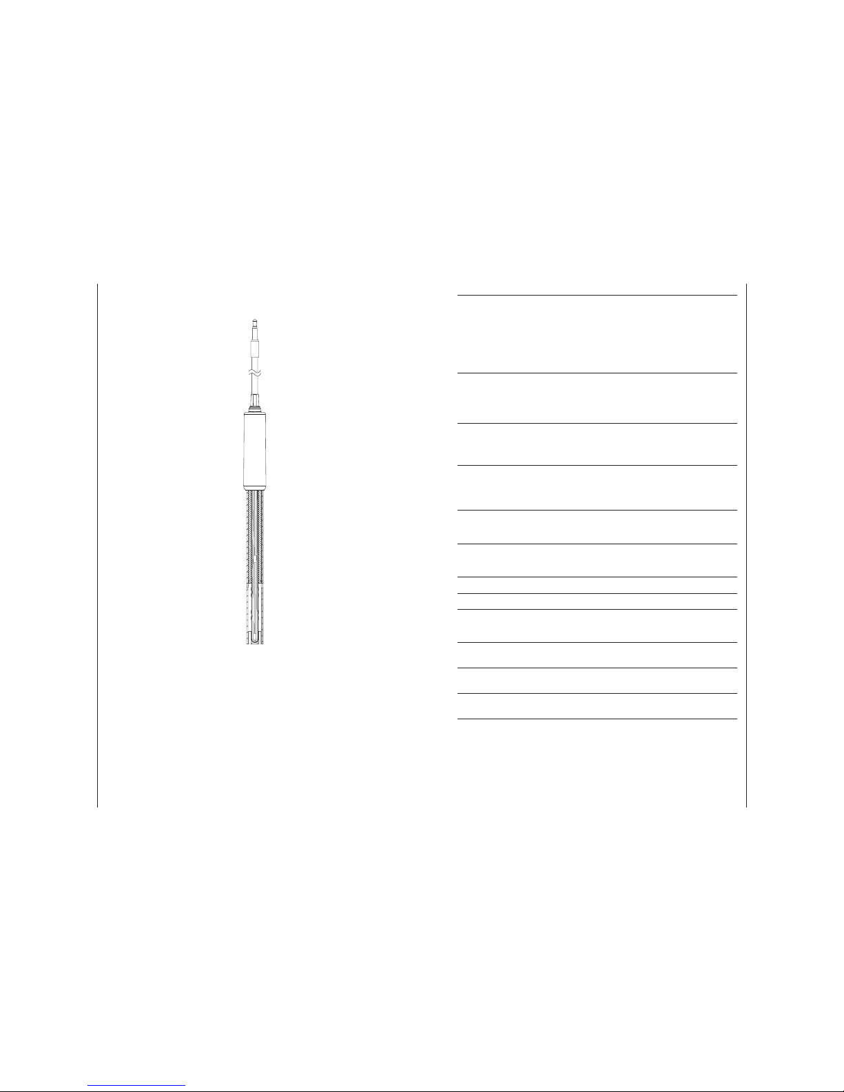
Probe Diagram.......................................................................................................................................................................... 6
Keypad Function.......................................................................................................................................................................7
Guide to Indicators.................................................................................................................................................................. 8
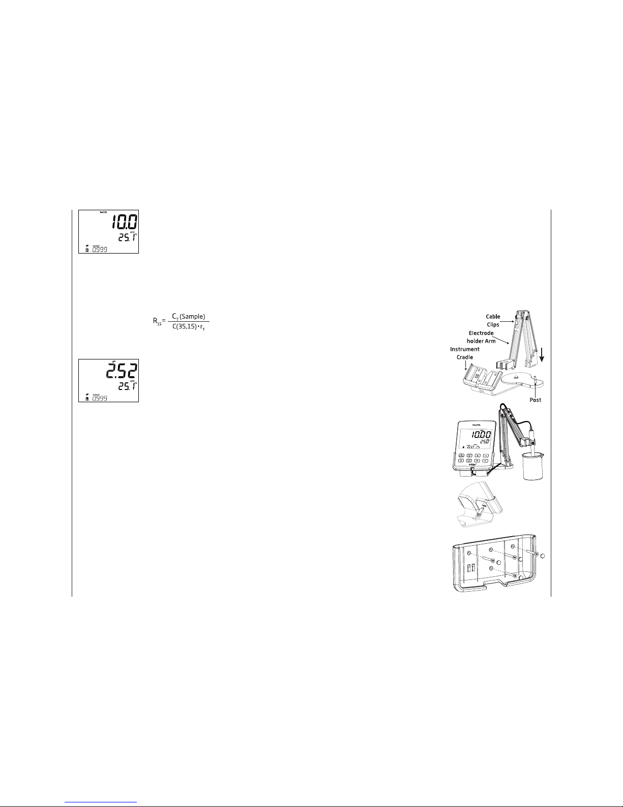
Setup/Installation....................................................................................................................9-19
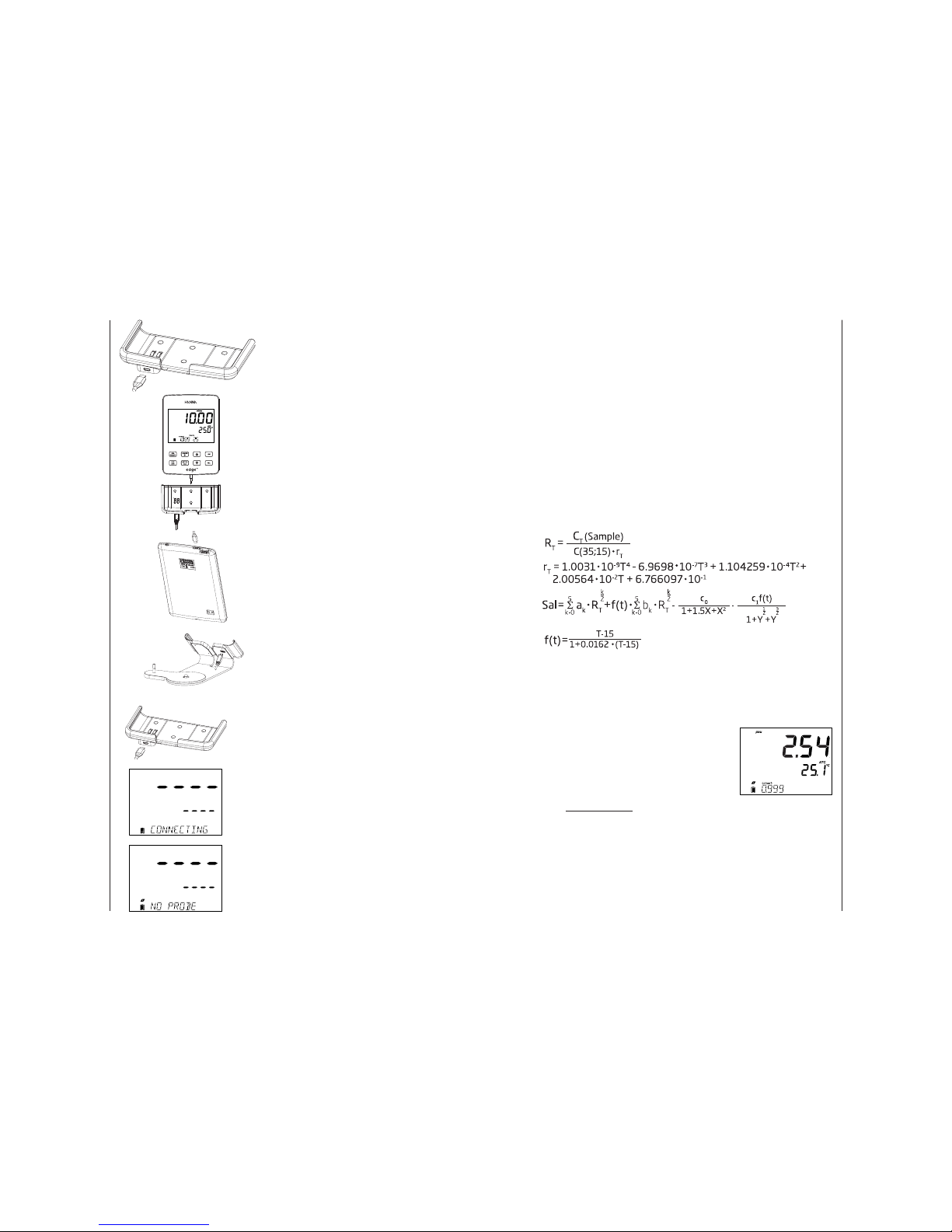
Setting Up edgeEC ®......................................................................................................................................................... 9-10
Electrode & Probe Connections ...................................................................................................................................... 10
General Setup...................................................................................................................................................................11-12
Basic Mode ............................................................................................................................................................................... 13
Logging Function ........................................................................................................................................................... 13-15
Viewing Logged Data................................................................................................................................................... 15-17
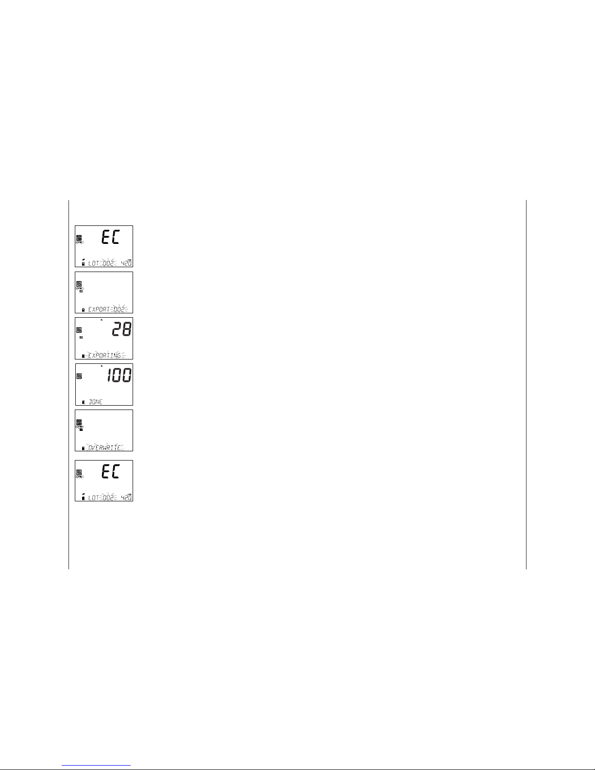
PC & Storage Interface.................................................................................................................................................18-19
Operational Guide .................................................................................................................20-32
Basic vs Standard EC Mode ...............................................................................................................................................20
EC Meter Conguration............................................................................................................................................... 20-23
EC/TDS Calibration........................................................................................................................................................ 23-24
NaCl % Calibration ...............................................................................................................................................................25
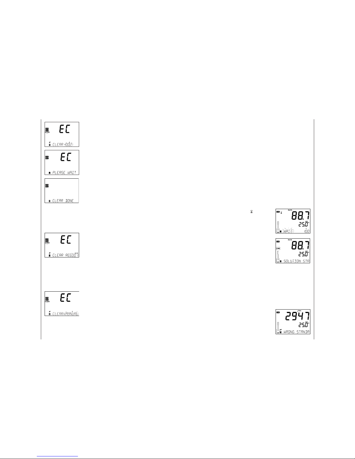
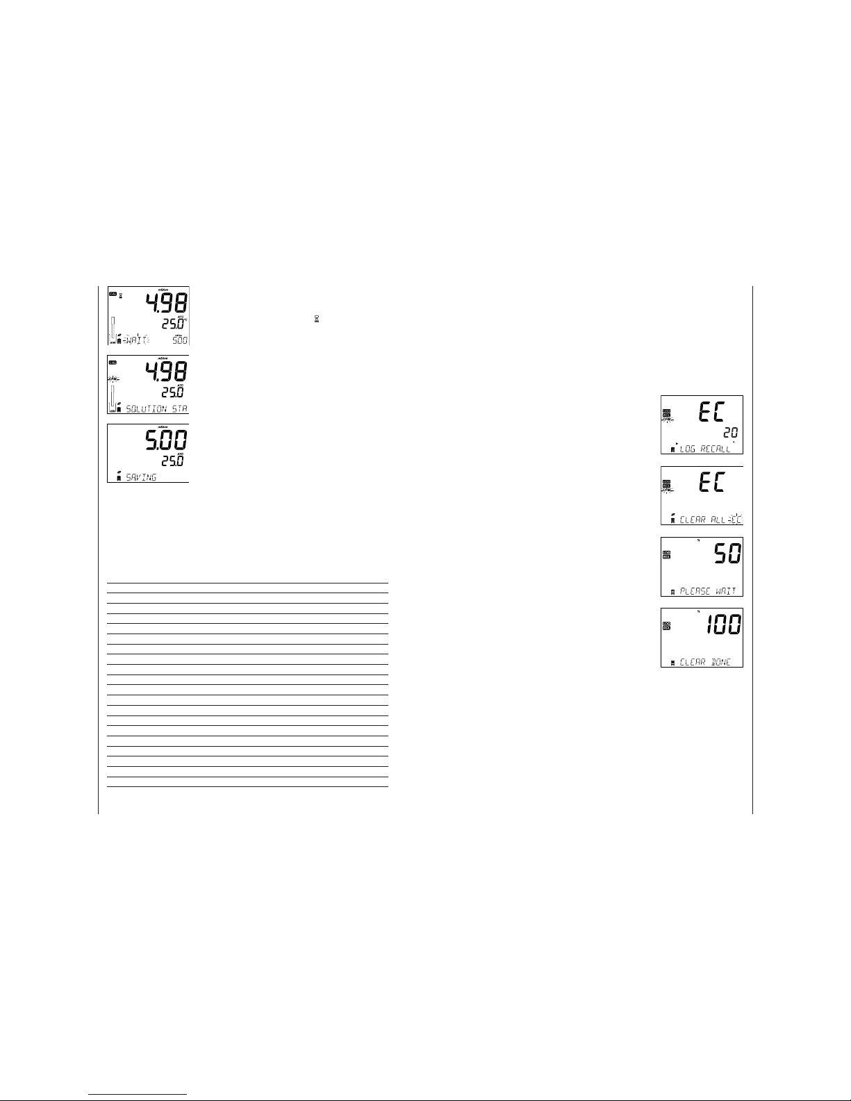
Calibration Messages................................................................................................................................................... 25-26
EC/TDS GLP Information ............................................................................................................................................ 26-27
NaCl % GLP Information.............................................................................................................................................28-29
EC/TDS Measurements............................................................................................................................................... 29-30
Salinity Measurements................................................................................................................................................30-32
Maintenance............................................................................................................................33-34
EC Probe Maintenance........................................................................................................................................................33
Troubleshooting Guide .......................................................................................................................................................34
Specications .........................................................................................................................35-36
Accessories ..................................................................................................................................... 37
Warranty ..........................................................................................................................................38

Warranty
38
Warranty edgeEC ® is guaranteed for two years against defects in workmanship and
materials when used for its intended purpose and maintained according
to instructions. Electrodes and probes are guaranteed for six months. This
warranty is limited to repair or replacement free of charge. Damage due to
accidents, misuse, tampering or lack of prescribed maintenance is not covered. If
service is required, contact your local Hanna Oce. If under warranty, report the
model number, date of purchase, serial number and the nature of the problem.
If the repair is not covered by the warranty, you will be notied of the charges
incurred. If the instrument is to be returned to Hanna Instruments, rst obtain a
Returned Goods Authorization number from the Technical Service department
and then send it with shipping costs prepaid. When shipping any instrument,
make sure it is properly packed for complete protection.
3
Remove the instrument & accessories from the packaging and verify damage
has not occurred during shipping. Remove protective lm from meter. Notify
your nearest Hanna Customer Service Center if damage is observed.
Each instrument is supplied with:
edge EC ® (HI2003)
Bench cradle
Wall cradle
Electrode holder
USB cable
5 Vdc Power Adapter
Instruction Manual
Quality Certicate
HI 763100: Digital 4 ring conductivity probe with integrated temperature sensor
1413 µS/cm and 12.88 mS/cm Conductivity Standard Sachets
Before using this product, make sure that it is entirely suitable for your specic
application and for the environment in which it is used.
Operation of this instrument may cause interference to other electronic
equipment, requiring the operator to take steps to correct interference. Any
variation introduced by the user to the supplied equipment may degrade the
instrument’s EMC performance.
To avoid damages or burns, do not put the instrument in microwave ovens.
For your and the instrument’s safety, do not use or store the instrument in
hazardous environments.
Note: Save all packing material until you are sure that the instrument works
correctly. Any defective item must be returned in its original packing.
Included
Safety
Measures

Diagram
4
edgeEC ® enables the user to make fast, accurate measurements of commonly
measured laboratory parameters using one of the Hanna edgeEC ® digital
sensors for Conductivity. Each digital sensors has a unique serial number. Once
connected to the meter, the sensor(s) are ready to measure their parameter
along with temperature.
The user interface permits you to adapt edgeEC ® to your exact measurement
requirements. The intuitive design simplies conguration, calibration,
measurement, data logging and transfer of data to a USB thumb drive or
computer. edgeEC ® also oers a basic operation mode that streamlines
measurement conguration and is useful for many routine applications. (Every
feature and measurement detail is designed to give you an edge in measurement
technology.)
edgeEC ® is versatile in many ways. The slim meter and probe can be used as
a portable device (using its rechargeable battery) or used in its bench or wall
cradles (that also power the meter) as a line-powered laboratory instrument.
Description
Product
Diagram
Side & Back
View
• Sleek, clean, intuitive design
• Internal clock and date
• Adjustable resolution
• Auto parameter recognition
• Dedicated GLP key
• GLP data included with logged data
• Basic mode for simplied operation
• Simplied data transfer to a PC
• Up to 8 hour battery life when used as a portable device
Diagram
Accessories 37
Accessories
Probes
HI 763100 EC/temperature probe
EC
Conductivity Solutions
HI 70030P 12880 μS/cm, 20 mL sachets (25 pcs.)
HI 70031P 1413 μS/cm, 20 mL sachets (25 pcs.)
HI 70039P 5000 μS/cm, 20 mL sachets (25 pcs.)
HI 7030M 12880 μS/cm, 230 mL bottle
HI 7031M 1413 μS/cm, 230 mL bottle
HI 7033M 84 μS/cm, 230 mL bottle
HI 7034M 80000 μS/cm, 230 mL bottle
HI 7035M 111800 μS/cm, 230 mL bottle
HI 7039M 5000 μS/cm), 230 mL bottle
HI 7030L 12880 μS/cm, 500 mL bottle
HI 7031L 1413 μS/cm, 500 mL bottle
HI 7033L 84 μS/cm, 500 mL bottle
HI 7034L 80000 μS/cm, 500 mL bottle
HI 7035L 111800 μS/cm, 500 mL bottle
HI 7039L 5000 μS/cm, 500 mL bottle
HI 7037L 100% NaCl sea water standard solution, 500 mL bottle
HI 8030L 12880 μS/cm, 500 mL FDA approved bottle
HI 8031L 1413 μS/cm, 500 mL FDA approved bottle
HI 8033L 84 μS/cm, 500 mL FDA approved bottle
HI 8034L 80000 μS/cm, 500 mL FDA approved bottle
HI 8035L 111800 μS/cm, 500 mL FDA approved bottle
HI 8039L 5000 μS/cm, 500 mL FDA approved bottle
Other Accessories
HI 75110/220U Voltage adapter from 115 Vac to 5 Vdc (USA plug)
HI 75110/220E Voltage adapter from 230 Vac to 5 Vdc (European plug)
HI 76404B Electrode holder
HI 2000WC Wall cradle
HI 2000BC Bench cradle
HI 920015 Micro USB cable

Specications
36
Additional Specications
PC Interface Micro USB
Storage Interface USB
Power Supply 5 VDC Adapter (included)
Environment 0-50 ºC (32-122 ºF) Max 95% RH non-condensing
Dimensions 202 x 140 x 12 mm (7.9 x 5.5 z 0.5”)
Weight 250g (8.82 oz)
Specications
Diagram 5
1. Liquid Crystal Display (LCD)
2. Capacitive Touch Keypad
3. 3 mm jack input for edgeEC ®
digital probes
4. Top mounted ON/OFF button
5. Micro USB device connection for
power or PC interface
6. Standard USB host connection
for data transfer to a USB
thumb-drive
Product
Diagram

Diagram
6
EC Electrode
• Probes process signal directly for noise free measurements
• Auto sensor recognition
• Store calibration specic data from the last calibration
• Are built with materials suitable for use in chemical analysis
• Have integrated temperature measurement
• Incorporate a 3 mm jack termination
• Unique serial ID in every probe for traceability
Probe
Probe
Diagram
Specications 35
EC TDS Salinity
Range
0.00to29.99μS/cm,
30.0 to 299.9 μS/cm,
300 to 2999 μS/cm,
3.00 to 29.99 mS/cm,
30.0 to 200.0mS/cm,
up to 500.0 mS/cm,
absolute
conductivity ‡
0.00to14.99ppm(mg/L),
15.0to149.9ppm(mg/L),
150.to1499.ppm(mg/L),
1.50 to 14.99 g/L,
15.0 to 100.0 g/L,
up to 400.0 g/L
absolute TDS ‡ (with
0.80 factor)
0.0 to 400.0% NaCl *,
2.00 to 42.00 PSU *,
0.0 to 80.0 g/L *
Resolution
0.01 μS/cm,
00.1 μS/cm,
1 μS/cm,
0.01 mS/cm,
00.1 mS/cm
0.01 ppm,
0.1 ppm,
1 ppm,
0.01 g/L,
0.1 g/L
0.1% NaCl,
0.01 PSU,
0.01 g/L
Accuracy
@ 25 °C / 77 °F
±1% of reading
(±0.05 μS/cm or 1
digit, whichever is
greater)
±1% of reading
(±0.03 ppm or 1 digit,
whichever is greater)
±1% of reading
Calibration
Single Cell Factor calibration; 6 standards
available: 84, 1413 μS/cm, 5.00, 12.88, 80.0,
111.8 mS/cm, 1 point offset: 0.00 μS/cm
Single point with
HI 7037L Standard
Temperature
compensation
Automatic -5 to 100º C (23 to 212º F)
NoTC - none
absolute conductivity.
Conductivity
temperature
coefficient
0.00 to 6.00% / ºC (for EC and TDS only). Default value is 1.90% / ºC
TDS factor 0.40 to 0.80 (default value is 0.50)
EC Probe HI 763100
Log feature
Up to 1000 * (400 basic mode) records organized in: Manual log on demand
(Max. 200 logs), Manual log on stability (Max. 200 logs), Interval logging *
(Max. 600 samples; 100 lots)
Temperature
Range -20.0 to 120.0 ºC ; -4.0 to 248.0 °F**
Temperature
Resolution 0.1 ºC; 0.1 ºF
Temperature
Accuracy ±0.5 ºC; ±0.9 ºF
Specications
* Standard Mode Only
** Temperature limits will be reduced to actual probe limits.
‡ Absolute conductivity (or TDS) is the conductivity (or TDS) value without temperature
compensation.

Maintenance
34
Symptoms Problems Solution
Readings uctuate up
and down (noise).
EC probe sleeve not
properly inserted; air
bubbles inside sleeve.
Reinstall the sleeve. Tap the probe to
remove air bubbles. Move to center
of beaker. Verify top hole in sleeve is
covered with solution.
The meter does not
accept the standard
solution for calibration.
Wrong Standard used or
the EC probe is defective.
Follow the cleaning procedure. If still
no results replace the probe. Verify
correct standard is selected.
The display shows EC,
TDS or Salinity readings
blinking.
Out of range in EC, TDS or
Salinity scale.
Verify the plastic shipping spacer has
been removed from probe. Recalibrate
the probe. Make sure the solution is in
specied range. Make sure the range is
not locked. (Select Auto range)
The meter does not
measure temperature.
“----” is displayed on
second LCD line.
Broken temperature
sensor.
Replace the probe.
The meter fails to
calibrate Salinity.
Incorrect EC calibration. Recalibrate the meter in EC range. Set
cell constant to 1.
At startup the meter
displays all LCD tags
permanently.
One of the keys is stuck. Check the keyboard or contact your
local Hanna Oce.
CAL “Prod” message at
startup.
Instrument was not
factory calibrated or lost
factory calibration.
Contact Hanna Technical Support for
help.
Troubleshooting
Guide
Diagram 7
Keypad
Function
1. CAL/MODIFY - Used to enter
and exit calibration mode. In
SETUP, used to initiate changes of a
conguration setting.
2. GLP/CFM - Used to display GLP
calibration information. In SETUP,
used to conrm change made. In
calibration, used to accept calibration
points.
3. RANGE/u- Used to select
measurement range. In SETUP, used
to move to right in pick list. In log RCL,
used to view GLP data for a data point.
4. SETUP/CLR - Used to enter/exit
SETUP mode. During calibration, used
to clear previous calibration data. In
log RCL, used to clear log records.
5. /- Used to scroll through
SETUP menu. Used to change
selection when modifying a
parameter in SETUP.
6. RCL (Recall) - Used to view
logged records or view % log memory
used.
7. LOG - Used to log data by
manual log on demand or manual log
on stability or to start/stop interval
logging.
Note: You can increase/
decrease the speed to
change the value of a
parameter.
Proceed as follows:
Press and hold down the
por qkey, then slide the
nger toward the double
apex to increase the speed
that a value changes.

Diagram
8
Guide to
Indicators
1. Mode tags
2. Conrm tag
3. USB connection status
4. Probes symbol
5. Battery symbol
6. Arrow tags, displayed when they
are available
7. Third LCD line, message area
8. Labels
9. Second LCD line, temperature
measurement
10. Temperature units
11. Temp. Compensation status
12. Measurement line
13. Measurement units
14. Stability Indicator
The third line of the LCD (9) is a dedicated message line. During measurement
the user may use the pq arrows to select desired message. Options include
date, time, calibration data, battery charge or no message. If a measurement
error or log status change occurs during measurement, the third line will display
a pertinent message.
Maintenance 33
Rinse the probe with clean water after measurements. If a more thorough
cleaning is required, remove the probe sleeve and clean the probe with a cloth
or a nonabrasive detergent. Make sure to reinsert the sleeve onto the probe
properly and in the right direction. After cleaning the probe, recalibrate the
instrument.
The insulator used to support the platinum rings is made of glass. Use extreme
caution when handling this probe.
Maintenance
EC Probe
Maintenance

Operational Guide
32
If the reading is out of range, the full-scale value
(400.0%) will be displayed blinking.
Natural Sea Water Scale
The Natural Sea Water Scale extends from 0 - 80.0 g/L. It determines salinity
based upon a conductivity ratio of sample to “standard seawater” at 15 °C.
Where R15 is the conductivity ratio and salinity is dened by the following
equation:
S = - 0.08996 + 28.2929729R15 + 12.80832R15
2
- 10.67869R15
3+ 5.98624R15
4-1.32311R15
5
Note: The formula can be applied for temperatures between 10 ºC and 31 ºC.
If the reading is out of the measurement range, the display will ash the highest
value possible and a warning message will be displayed. If this occurs during a
log a “!” will be placed next to the measurement unit. Data found in the CSV le
with a ”!” should not be considered relible.
Salinity
Measurements
Setup/Installation 9
The main operating modes of edgeEC ® are setup, calibration, measurement,
data logging, and data export. Follow this general outline of steps to get you
started. The following topics are expanded upon in the sections that follow in
this manual.
1. Familiarize yourself with the design features of this unique meter.
2. Decide how the meter will be used and set up the wall or bench cradle in a
clean area near line power.
3. Turn edgeEC ® on using the ON/OFF button located on the top of the meter.
4. Plug in the probe required for measurement.
5. SETUP the measurement parameters required for the measurement you
will be making.
6. Calibrate the sensor/probe.
You are now ready for measurements.
Bench Cradle Setup
Insert electrode holder arm into the post
on the pivoting base.
Connect the probe connector to the
socket located at the bottom of the
instrument.
Slide edgeEC ® into the cradle while
positioning the probe cable behind the
cradle. Put the probe/sensor into the
electrode holder and secure cable in
clips.
Connect the power adapter cable to the
rear socket of the bench cradle. Connect
the other end to the power adapter and
plug into line power. Verify the battery
icon indicates charging.
Wall Cradle Setup
Choose suitable wall location. (Use 2.5
mm or US #3 bit). Fasten the wall cradle
using the provided screws. Snap cover
over screw heads.
Setup/
Installation
Setting Up
edgeEC ®

Setup/Installation
10
Connect the power adapter cable to the
bottom socket of the wall cradle. Connect
the other end to the power adapter and
plug into line power.
Connect the 3mm probe jack to the socket
located at the bottom of edgeEC ®.
Slide edgeEC ® into the wall cradle. Verify
the battery icon indicates charging.
Power Connection
Alternatively to using the cradle for
power, edgeEC ® can be powered by micro
USB socket at the top. Plug the 5 VDC
adapter into the power supply socket or by
connecting directly to a PC.
Note: edgeEC ® is supplied with a
rechargeable battery inside, which
provides about 8 hours of continuous use.
Whenever edgeEC ® is connected to the
power adapter or to a PC, the battery is
charging
Connect the 3 mm probe jack to the probe
input located on the bottom of edgeEC ®.
Make sure the probe is completely
connected. If the probe is recognized,
“CONNECTING” message is displayed along
with sensor model.
If the probe is not connected or not
recognized, “NO PROBE” message is
displayed.
Setting Up
edgeEC ®
Electrode
& Probe
Connections
Operational Guide 31
Note:
• These are for determining salinity as they relate to general oceanographic
use.
• Practical salinity and the Natural Seawater require a conductivity
calibration.
• NaCl % requires a calibration in HI 70371 standard.
PSU - Practical Salinity Units
The practical salinity (S) of seawater relates the ratio of electrical conductivity
of a normal seawater sample at 15 ºC and 1 atmosphere to a potassium chloride
solution (KCl) with a mass of 32.4356 g/Kg water at the same temperature and
pressure.
Under these conditions the ratio is equal to 1, and S=35. The practical salinity
scale may be applied to values to through 42 PSU at temperatures between -2
to 35 ºC.
According to the denition, salinity of a sample in PSU (practical salinity units) is
calculated using the following formula:
NaCl % Percent Scale
The NaCl % scale is an older salinity scale used for seawater salinity. In this scale
100% salinity is equivalent to roughly 10% solids. High percentages were made
by evaporation. To display NaCl in % units, enter SETUP and select NaCl% unit.
Press the RANGE key until “NaCl%” is displayed on the LCD. The instrument will
display the NaCl% reading on the rst LCD line and the temperature reading on
the second LCD line.
Salinity
Measurements
f(t)= T-15
1 + 0.0162•(t-15)
a0= 0.008
a1= -0.1692
a2= 25.3851
a3= 14.0941
a4= -7.0261
a5= 2.7081
b0= 0.0005
b1= -0.0056
b2= -0.0066
b3= -0.0375
b4= 0.0636
b5= -0.01442
c0= 0.008
c1= 0.0005
X = 400RT
Y = 100RT
RT - ratio of sample conductivity to standard conductivity at Temp =(T)
CT(sample) - uncompensated conductivity at T ºC;
C(35,15) =42.914µS/cm - the corresponding conductivity of KCI solution
containing a mass of 32.4356 g KCl/1 Kg solution
rT- Temperature compensation polynomial

Operational Guide
30
No Temperature Compensation (No TC): The temperature value is displayed,
but not taken into account. When this option is selected, the “NoTC” tag will be
displayed. The reading displayed on the primary LCD is the uncompensated EC
or TDS value.
Note:
• The default compensation mode is ATC.
• The compensation is referenced to the selected reference temperature
(see SETUP for details).
If temperature compensation is selected, measurements are compensated
using the temperature coecient (default value 1.90 %/ºC, is recommended for
natural water samples).
To change the temperature coecient, enter the SETUP mode and select
“T.Coef.(%/ºC)” (see SETUP).
The current temperature coecient can be viewed on the third LCD line by
pressing the pq keys until it is displayed. The value is displayed along with
Cell Factor (the factor that is used to convert the measured conductance to
conductivity, based on the geometry of the cell). If the temperature reading is
out of range, the closest full scale value will be displayed with “ºC” blinking on
the second LCD line.
Error Messages During Measurement
If the EC temperature exceeds the limit of the probe, the message “PROBE
OUT OF SPEC” will scroll on the third LCD line. The temperature will continue to
be displayed blinking. If temperature exceeds the meter specication of 120º
C, then “120º C” will blink on the display. If interval logging, the message “OUT
OF SPEC.” will alternate with the Log specic messages in both of these cases.
The Log le will indicate a “ºC!” next to the data. In the
case the temperature sensor is damaged, “BROKEN
TEMPERATURE SENSOR” , “---” along with NoTC tag
will be displayed and the unit tag will blink on the LCD.
If logging when this occurs, the Log le will indicate
“ºC!!” next to the data. Absolute conductivity (NoTC)
will be marked with an “A” in the CSV les and dashes
will appear in the temperature eld.
TDS Measurements
Press the RANGE key. The instrument will switch
to TDS measuring range. The TDS reading will be
displayed on the rst LCD line and the temperature
reading on the second LCD line. If the reading is out of
range, the full-scale value (100.0 g/L for ATC mode or
400.0 g/L for uncompensated TDS) will be displayed
blinking along with a message on the display.
Salinity Measurements (Not Available In Basic Mode)
Press the RANGE key twice to switch from conductivity to the congured Salinity
scale. Verify the desired scale is congured in SETUP. The meter supports three
salinity scales: Practical Scale 1978, Percent Scale %, and Natural Sea Water
1966, [g/L]. (Information on the 3 scales follows)
Salinity
Measurements
EC/TDS
Measurements
Setup/Installation 11
The following General Setup options are displayed regardless of the sensor
being used. These settings remain when switching to another probe type or
when no probe is attached. Options are tabulated in the table below with choices
and default values. Options are accessed by pressing SETUP. Loop through the
options by using the pq arrows. To modify a setting, press MODIFY. The option
may be modied by using u, pand qkeys. Press CFM to conrm the change. To
exit SETUP press SETUP.
Option Description Choices Default Basic mode
*Only seen
when cable
connection
between micro
USB and PC is
made.
Select if PC is
being used for
charging battery
(and meter
will be used
for logging) or
if Data will be
exported to
the PC.
LOG ON EDGE or
EXPORT TO PC LOG ON EDGE Available
Log
Select log type
to be used
from 3 types of
logging:
Manual log on
demand
Manual log
on stability
(3 types of
stability criteria
available)
Timed interval
lot logging
Manual Log
Stability Log:
Fast, Medium,
Accurate;
Interval Log:
Seconds: 5, 10,
30; Interval Log
Minutes: 1, 2, 5,
15, 30, 60, 120,
180.
Interval
(5 Sec)
Manual log
or
Stability log:
Medium
Set Calibration
Expiration
Warning
Meter will
indicate “CAL
DUE” when
set time in this
parameter has
been exceeded.
1, 2, 3, 4, 5, 6, 7
days or OFF 7 days Not available
Probe Specic Parameters that are specic to a measurement type are inserted here in
the SETUP list.
Set Date
Press MODIFY
key to Set current
date, displayed
in ISO format.
Press CFM to save
changes.
YYYY/MM/DD
Date Set date Available
Set Time
Press MODIFY
key to Set current
time, displayed
in ISO format.
Press CFM to save
changes.
24hr:MM:SS
Time Set time Available
General
Setup

Setup/Installation
12
Option Description Choices Default Basic mode
Set Auto O
Used to save
battery life by
automatically
turning o when
no key press is
detected for
time set and
meter is not in
active logging or
calibration mode.
5, 10, 30, 60
Min
or O
10 min Available
Sound
If enabled, a
short audible
tone is produced
for key stroke
or calibration
conrmation and
a longer tone for
wrong key.
On or O On Available
Temperature
Unit
Select degree
Celsius or
Fahrenheit scale
for displayed
and logged
temperatures.
ºC or ºF ºC Available
LCD Contrast
Permits
modication
of the display
contrast for
various lighting
conditions.
1 to 8 3 Available
Flash Format*
Only seen when
log errors are
present.
Permits
formatting the
ash drive.
On or O O Available
Message
Transition
User may choose
how messages
are displayed on
third LCD line of
display.
Word scroll
messages or
letter scroll
messages
Letter scroll
messages Available
Reset Cong To
Default
Press the MODIFY key and CFM (when prompted) to
reset parameters.
Available:
RESETS with
Basic Mode OFF.
Instrument
Firmware/ Probe
Firmware
Displays rmware
version of meter.
Using the u
key switches to
Probe rmware
(if connected)
and diagnostic
mode for
troubleshooting.
View only
Current
rmware
version.
Available
Meter ID/
Meter SN/
Probe SN
User ID and
Serial Number of
meter and probe
(if connected).
Use u to
change between
the three
parameters.
Meter ID is user
selectable
0000/ Serial
Number Available
*Note: Options that are seen under special conditions only.
General
Setup
Operational Guide 29
If enabled, the number of days since the calibration
expired. (i.e. “CAL EXPIRED 2 DAYS AGO”).
The serial number of the probe.
Note: Press GLP at any moment and the instrument will return to measurement
mode.
The RANGE key will change measurement from conductivity to TDS to Salinity.
Conductivity Measurements
Connect the conductivity probe to the instrument and
wait until probe parameters are loaded. The following
message is then displayed on the LCD: “PROBE
CONNECTED”.
Verify if the probe has been calibrated. Suspend the probe into the solution
to be tested. The sleeve holes must be completely submersed. Tap the probe
repeatedly to remove any air bubbles that may be trapped inside the sleeve.
The conductivity value will be displayed on the rst
LCD line, the temperature on the second LCD line and
calibration or range specic information on the third
LCD line.
To toggle between information displayed on the third LCD line, use the ARROW
keys.
If the reading is out of range when the range is set to
automatic, the full-scale value (200.0 mS/cm for ATC
mode or 500.0 mS/cm for absolute conductivity) will
be displayed blinking.
Note: Temperature-compensation and absolute conductivity (NoTC) are
selected in the SETUP conguration.
Automatic Temperature Compensation (ATC): The conductivity probe has
a built-in temperature sensor; the temperature value is used to automatically
compensate the EC/TDS reading. When this option is selected, “ATC” tag is
displayed. A temperature coecient for the sample must also be set.
NaCl % GLP
Information
EC/TDS
Measurements

Operational Guide
28
NaCl % GLP
Information NaCl % Calibration Data in GLP
To view the NaCl% calibration data, press GLP when the instrument is in NaCl%
measurement mode. Use the ARROW keys to scroll through the calibration data.
The instrument will display the calibration temperature and solution.
The cell factor in cm-1 determined from the calibration
with the current reading.
The salinity coecient determined from the
calibration together with the current reading.
The Solution Standard together with the calibrated
temperature.
The time (hh:mm:ss) of the last calibration together
with the current reading.
The date (yyyy.mm.dd) of the last calibration together
with the current reading.
Calibration Expiration status together with the
current reading:
If disabled, “EXPIRATION WARNING DISABLED” is
displayed.
If enabled, the number of days until the calibration
alarm “CAL DUE” will be displayed. (i.e. “CAL EXPIRES
IN 2 DAYS”)
Setup/Installation 13
edgeEC ® oers a basic operation mode that streamlines measurement
conguration for EC measurements and is useful for many routine applications.
Basic EC reduces specic EC SETUP parameters to 3. The meter defaults settings
to common parameters and auto ranges measurements automatically. The
Basic EC meter may be used for conductivity and TDS measurements (salinity
is not available). Interval logging is also eliminated. Manual and Manual medium
stability Log on demand are still functional.
Note:
• If powering edgeEC ® through the micro USB connector to a PC, a SETUP
option will require the choice “LOG ON EDGE” or “EXPORT TO PC“.
• 1000 log records can be stored into edgeEC ® memory. This memory is
shared between all logging types (Manual, Manual Stability, Interval logs).
• The maximum number of records for an Interval lot is 600 records (provided
log space is available).
• A record is a stored reading and a lot is a group of records.
Each time an Interval log is initiated, a new lot is
created. The maximum number of Interval lots that
may be stored is 100. If a 101st lot is attempted, “MAX
LOTS” will be displayed. Some lots will need to be
deleted. The lot numbering is up to 999 and restarts if
all lot logs are deleted. All log on demand and stability
log on demand are stored in a single lot. The maximum
number of records that may be stored in a Manual or Stability lot is 200 records.
If the log memory is full during any logging session,
the “LOG FULL“ message will be displayed on the
third LCD line for a brief moment and logging will
cease. The display will return to the measurement
screen.
Logging type is congured in SETUP.
Types of Logging
Interval logging: A continuous log recorded using a user-selected timed period.
(This is not available in Basic mode).
Manual log on demand: Readings are logged each time LOG key is pressed. All of
the records are stored in a single Manual lot. New records made on dierent days
are stored in the same Manual lot.
Manual Stability log on demand: A log on demand that is made each time LOG
key is pressed and the stability criteria is reached. Stability criteria may be set to
Fast, Medium or Accurate settings.
Basic Mode
Logging
Function

Setup/Installation
14
In Setup mode, choose log parameter, press MODIFY then use the uarrow to
select between Interval, Manual, or Stability. When Interval is displayed, use the
pand qarrows to select the setting for the timed interval. When Stability is
displayed, use the pand qto select the measurement stability setting.
A complete set of GLP information including date, time, range selection,
temperature reading, calibration information and probe serial number is stored
with each log made.
Interval Logging
Select Interval and sampling period in the SETUP menu (Not available in Basic
mode). To start Interval logging, press the LOG key while the instrument is in
measurement mode.
A “PLEASE WAIT” message will be displayed followed
by the number of free spaces. During active interval
logging, lot information is displayed on the third
LCD line. The line indicates in which lot the data will
be placed and keeps track of the number of logged
records taken. The “LOG“ tag is continuously on during
active logging.
Pressing uduring an interval log will display the
number of logs available.
Pressing the LOG key again will stop the Interval
logging session. The “LOG STOPPED“ message will be
displayed for a few seconds.
If a sensor failure occurs during interval logging, the
message “OUT OF SPEC.” will alternate with logging
information.
Manual Logging
Select Manual in the SETUP menu. To initiate a
Manual log, press the LOG key while the instrument
is in measurement. The “PLEASE WAIT” screen will
be displayed briey followed by a screen indicating
the measurement has been saved and then a screen
indicating the log record number.
The “LOG” tag will be displayed on all 3 screens.
“PLEASE WAIT”
“SAVED” with the log record number
“FREE” with the number of free spaces available
Logging
Function
Operational Guide 27
The reference temperature together with the current
reading.
The time (hh:mm:ss) of the last calibration together
with the current reading.
The date (yyyy.mm.dd) of the last calibration together
with the current reading.
Calibration Expiration status together with the
current reading:
If disabled, “EXPIRATION WARNING DISABLED” is
displayed.
If enabled, the number of days until the calibration
alarm “CAL DUE” will be displayed. (i.e. “CAL EXPIRES
IN 2 DAYS”)
If enabled, the number of days since the calibration
expired. (i.e. “CAL EXPIRED 2 DAYS AGO”).
The serial number of the probe together with the
current reading.
EC/TDS GLP
Information

Operational Guide
26
Wrong Standard Temperature
If the temperature is out of the 0.0 to 60.0 ºC range,
“WRONG STANDARD TEMPERATURE” message will be
displayed and the temperature value will blink.
GLP is a set of functions that allows storage and retrieval of data regarding the
maintenance and status of the electrode. The following information can be
viewed on the third LCD line during measurement:
TEMPERATURE SENSOR problem (if there is one)
CAL DUE or CELL FACTOR
T.Coef. or T.Ref. (User selected)
TIME
DATE
RANGE
BATTERY or CHARGE STATUS
To view more information, enter GLP mode by pressing GLP key.
EC calibration data is stored automatically after a successful calibration.
To view the EC calibration data, press GLP when the instrument is in EC
measurement mode. The instrument will display the calibration standard and
the temperature of the calibrated standard. Use the pq keys to scroll through
the calibration data displayed on the third LCD line.
The cell factor in cm-1 determined from the calibration
with the current reading.
The calibration oset factor in μS/cm together with
the current reading.
The Solution Standard and calibration temperature.
The temperature coecient used during calibration
with the current reading.
Calibration
Messages
EC/TDS GLP
Information
Setup/Installation 15
Stability Logging
Select Stability and choose measurement stability
criteria in the SETUP menu. Only Stability Medium
is available in Basic mode. To initiate the Stability
log, press the LOG key while the instrument is in
measurement.
The “PLEASE WAIT” screen will be displayed briey
followed by a screen showing the stability tag, “LOG”
tag and a “WAITING” message. The log can be stopped
while the “WAITING” message is displayed by pressing
LOG again.
When the stability selected criteria has been met,
a “SAVED” message will be displayed followed by a
screen indicating how much log space is available. The
“LOG” tag will be displayed on all 4 screens.
“PLEASE WAIT”
“WAITING”
“SAVED” with the log record number
“FREE” with the number of free spaces available
All log records stored on edgeEC ® may be viewed on the meter by pressing the
RCL key.
If no sensor or probe is connected, use the uarrow
to select the desired measurement type. Press CFM to
display those logs.
Choices are:
• Manual log on demand lot,
• Manual log on stability lot,
• Individual Interval logging lots.
If no data was logged for the selected measurement
range, the instrument displays the following
messages:
• “NO MANUAL LOGS”
• “NO STABILITY LOGS”
Press CFM to enter inside lot information to view recorded data.
Use the ARROW keys to toggle between dierent records.
Use uto display GLP data including calibration information, date, time, etc.
Press CLR then CFM when deleting records or lots.
Press RCL to exit the logging type.
Press RCL to return to the measurement screen.
Logging
Function
Viewing
Logged
Data

Setup/Installation
16
Delete Logging Type/Lot
Press RCL and select the parameter log.
Use the pq keys to select the Manual/Stability
records or Interval lots to delete. Press CLR. The
instrument will display “CLEAR MANUAL” for Manual
Records, “CLEAR STAB” for Stability Records.
For Interval lots, the message “CLEAR”, followed by the
selected lot will be displayed with “CFM” tag blinking.
Press the pq keys to select a dierent lot. Press CFM.
The instrument will display “PLEASE WAIT”.
“CLEAR DONE” is displayed for a few seconds after the
selected Interval lot is deleted.
Delete Records (Manual and Stability log on demand)
To delete individual records (Manual and Stability logs only), enter Manual
(Stability) log by pressing CFM when Manual (Stability) is displayed. Use the
ARROW keys to select the record to be deleted and then press CLR.
The instrument will display “CLEAR REC.“ and record
number along with “CFM” tag blinking. Use the ARROW
keys to select another record if necessary.
Press CFM. The instrument will display “PLEASE WAIT” and then “CLEAR
DONE” message. When individual logs are deleted within saved MANUAL or
STABILITY logs, the logs will renumber, lling in the deleted data but staying in
chronological order.
To delete all records of the MANUAL (STABILITY) log, proceed as described on
page 16 for LOTS.
Select the Manual (Stability) lot and press CLR.
The ”CLEAR” message will be displayed along with
”MANUAL” or “STABILITY” and CFM tag blinking on
the LCD. Press the CFM key to conrm the deleting of
the selected lot (MANUAL or STABILITY) or all records.
Press CLR to exit without deleting.
Viewing
Logged
Data
Operational Guide 25
Preparation
Pour a small quantity of the calibration solution into a beaker. If possible, use a
plastic beaker to minimize any EMC interferences.
Before pressing CAL verify in SETUP:
• Basic mode is o.
• Salinity Scale is set to NaCl%.
In measurement mode use the RANGE key to select the Salinity measurement.
The NaCl% tag will be on. NaCl calibration is a single point calibration at 100.0%
NaCl. Use the HI 7037L calibration solution (sea water solution) as a 100% NaCl
calibration solution.
Procedure
Rinse the probe with some of the HI 7037L calibration solution or deionized
water. Shake o excess solution. Submerse the probe in the calibration solution.
The sleeve holes must be completely submersed. If possible, center the probe in
the beaker away from the bottom or beaker walls. Raise and lower the probe to
rell the center cavity and tap the probe repeatedly to remove any air bubbles
that may be trapped inside the sleeve.
Press CAL to enter calibration. The ” “, ”STIR” and
“CAL” tags will turn on and the rst LCD line will
display the percent NaCl reading, the second LCD line
will display the temperature and the third LCD line will
display ”WAIT” message blinking until the reading is
stable.
When the reading is stable and close to the standard,
“CFM” tag will blink and “SOLUTION STANDARD”
message will be displayed.
Press CFM to conrm calibration.
The Instrument displays “SAVING”, stores the calibration values and returns to
measurement mode.
Note: If a new EC calibration is performed, the NaCl calibration is automatically
cleared. A new NaCl calibration is required.
Wrong Standard
If the reading is too far from the expected value, the
message “WRONG STANDARD” will scroll. Calibration
cannot be conrmed. In this case check if the
calibration solution has been used correctly or clean
the probe by following the instructions for EC PROBE
MAINTENANCE (see page 33).
NaCl %
Calibration
Calibration
Messages

Operational Guide
24
EC/TDS
Calibration
Press CAL to enter calibration. The “CAL” tag and the
recognized standard value will appear on the third
LCD line. If necessary, press the ARROW keys to select
a dierent standard value. The “ “ along with “STIR”
tag will be displayed and “WAIT” will blink on the LCD
until the reading is stable.
When the reading is stable and close to the selected
standard, “CFM” tag will blink, the message “ SOL STD”
and the value will be displayed.
Press CFM to conrm calibration. The instrument
displays “SAVING”, stores the calibration values and
returns to measurement mode.
Conductivity vs Temperature Chart
The following table lists the temperature dependence of Hanna EC calibration
standards. edgeEC ® uses these values and their temperature coecients during
calibration.
ºC ºF
HI7030
HI8030
(μS/cm)
HI7031
HI8031
(μS/cm)
HI7033
HI8033
(μS/cm)
HI7034
HI8034
(μS/cm)
HI7035
HI8035
(μS/cm)
HI7039
HI8039
(μS/cm)
0 32 7150 776 64 48300 65400 2760
5 41 8220 896 65 53500 74100 3180
10 50 9330 1020 67 59600 83200 3615
15 59 10480 1147 68 65400 92500 4063
16 60.8 10720 1173 70 67200 94400 4155
17 62.6 10950 1199 71 68500 96300 4245
18 64.4 11190 1225 73 69800 98200 4337
19 66.2 11430 1251 74 71300 100200 4429
20 68 11670 1278 76 72400 102100 4523
21 69.8 11910 1305 78 74000 104000 4617
22 71.6 12150 1332 79 75200 105900 4711
23 73.4 12390 1359 81 76500 107900 4805
24 75.2 12640 1386 82 78300 109800 4902
25 77 12880 1413 84 80000 111800 5000
26 78.8 13130 1440 86 81300 113800 5096
27 80.6 13370 1467 87 83000 115700 5190
28 82.4 13620 1494 89 84900 117700 5286
29 84.2 13870 1521 90 86300 119700 5383
30 86 14120 1548 92 88200 121800 5479
31 87.8 14370 1575 94 90000 123900 5575
Setup/Installation 17
The lot number is used to identify particular sets of data. The lot numbers
are allocated successively until 100, even if some lots were deleted. The total
number of lots that can be saved is 100. If some are deleted (for example 1-50),
fty additional logs may be stored. These will be numbered 101-150. The lots are
allocated successively (provided available memory space) until 999 is reached.
After this, it is necessary to delete all the LOT logs to start over the numbering.
Delete All
All logs may be deleted in a single clear. This function will delete all MANUAL,
STABILITY and INTERVAL logs.
Press the RCL key while EC is displayed on the rst
LCD line, and the third LCD line message states “LOG
RECALL”. Press CLR.
“CLEAR ALL” will be displayed with “CFM” and “EC“
tags blinking. Press CFM.
“PLEASE WAIT” and the percent cleared will be
displayed until completed.
Note: If CLR is pressed in error, press CLR again to exit
without deleting.
Viewing
Logged
Data

Setup/Installation
18
Logged data on edgeEC ® can be transferred from the meter to a USB ash drive
by using the log recall function. The minimum requirement for the drive is USB
2.0. Select the EC record you wish to export and follow the simple steps below.
Connect USB ash drive to the USB port, located on
the top of the meter. Press the RCL key. Press the CFM
key. Select Manual, Stability, or interval lots by using
the pq keys. Press the LOG key (not CFM). The “USB
HOST” tag should come on.
“PLEASE WAIT” message appears followed by
“EXPORT”. Press CFM to export the selected record or
lot. If CFM is not pressed within 10 seconds, the USB
host will become inactive.
The meter will display the percentage of export.
The export percentage should go to 100%. Remove
USB ash drive.
If the selected le is already saved on the ash drive,
edgeEC ® will ask for conrmation of overwriting the
existing le. The message “OVERWRITE’ and “CFM”
tag will blink. Press CFM for overwriting the existing
le or CAL to exit without exporting.
After exporting the display will return to the
selected le. Press the RCL key twice to return to
measurements.
Note: Do not remove USB ash drive during an active export transfer.
PC & Storage
Interface
Operational Guide 23
6. Press CFM. The message “MANUAL CALIBRATION CLEARS PREVIOUS
CALIBRATIONS” will be displayed on the third line LCD. “CAL” and “CFM”tags
will blink. Press CFM to conrm the manual calibration.
Note: GLP will display “Manual” for a standard. Using this calibration technique
will erase any previous calibrations done in CAL. Log les will indicate “MANUAL”
as standard.
User Selectable EC/TDS Range (Not Available In Basic Mode)
The EC and TDS measurements may be congured in SETUP as AUTO (meaning
auto ranging, the measurement automatically nds the correct conductivity
or TDS unit and resolution), or it may be congured with a user-selected
measurement range and resolution (if you know ahead of time where your
samples will fall). If AUTO is selected, the meter will select the scale with
the highest possible resolution, but may change in the middle of a series of
measurements changing units and displayed resolution.
Note: The selected range is only active during measurements. Auto ranging is
used during calibration. If a xed range is selected and during measurement
goes beyond the range limits, the full scale value of that range will ash on the
display. All log data in the CSV les will be displayed in uS/cm.
General Guidelines
Calibrate the instrument frequently, especially if high accuracy is required.
The instrument should be recalibrated:
• Whenever the EC probe is replaced.
• At least once a week.
• After testing aggressive chemicals.
• If “CAL DUE” is displayed on the third LCD line.
Every time you calibrate the instrument use fresh standard and perform
electrode maintenance as required. It is recommended to choose a calibration
standard that is close to the sample.
Preparation
Pour small quantities of the standard solutions into a beaker. If possible, use a
plastic beaker to minimize any EMC interferences. For accurate calibration and to
minimize cross-contamination, use two beakers for the standard solution; one
for rinsing the probe and one for calibration.
Procedure
Select standard to be used for calibration. 0.00 μS (probe in air) may be used for
an oset calibration. This should be done rst. Hanna Conductivity standards
are available at 84 μS/cm, 1413 μS/cm, 5.00 mS/cm, 12.88 mS/cm, 80.0 mS/cm,
111.8 mS/cm and are used for the cell factor calibration.
Rinse the probe with calibration solution or deionized water. Shake o excess
solution. Submerse the probe in the calibration solution. The sleeve holes must
be completely submersed. If possible, center the probe in the beaker away from
the bottom or beaker walls.
Raise and lower the probe to rell the center cavity and tap the probe repeatedly
to remove any air bubbles that may be trapped inside the sleeve.
EC Meter
Conguration
EC/TDS
Calibration

Operational Guide
22
EC Meter
Conguration
Option Description Choices Default Basic mode
EC Range If AUTO is used,
edgeEC ® will
automatically
nd the correct
conductivity
range and
unit. If a xed
value is used,
measurements
made outside
the ranges are
considered
Out of Range,
but units will
remain xed
throughout the
measurement.
AUTO,
29.99 μS/cm,
299.9 μS/cm,
2999 μS/cm,
29.99 mS/cm,
200.0 mS/cm,
500.0 mS/cm
AUTO Not available but
measurement
autoranges as
needed.
TDS Range If AUTO is used,
edgeEC ® will
automatically
nd the
correct TDS
measurement
range and
units. If a xed
value is used,
measurements
made outside
the ranges are
considered
Out of Range,
but units will
remain xed
throughout the
measurement.
AUTO,
14.99 mg/L,
149.9 mg/L,
1499 mg/L,
14.99 g/L,
100.0 g/L,
400 g/L
AUTO Not available but
measurement
autoranges as
needed.
TDS Unit Select units of
measurement
for TDS
measurement.
mg/L or ppm ppm Available to
select.
EC Salinity Scale Three
measurement
scales are
available
for salinity
measurement
in Seawater.
(Practical
Salinity Scale,
Percent Scale
and Natural
Seawater Scale).
PSU, NaCl%, g/L NaCl% Not available.
Cell Factor (cm-1) Manual Calibration
This option may be used to perform a manual calibration in a custom standard.
1. Rinse the probe with a aliquot of standard and shake o excess solution.
2. Place the probe in the standard. The sleeve holes must be covered with
solution.
3. Press SETUP and use the ARROW keys to get to C.F. (cm-1)
4. Press Modify.
5. Use the pq keys to change C.F. (cm-1) until the display reads the Custom
Standard value.
Setup/Installation 19
Logged data on the edgeEC ® can be transferred from the meter to a PC by
following these simple directions. Suitable operating systems include Windows
(Xp minimum), OS X or Linux.
1. Connect edgeEC ® to the PC using the supplied micro USB cable.
2. Turn on edgeEC ®.
3. Press SETUP and select “LOG ON EDGE”.
4. Press MODIFY then use pq keys to change to “EXPORT TO USB”.
5. Press CFM and the USB/PC Tag is displayed.
6. Press SETUP to exit.
The PC should detect the USB as a removable drive. Open the drive to view the
stored les. Log les are formatted as Comma separated values (*.CSV) and can
be opened with any text editor or spreadsheet program.
Note:
• Western Europe (ISO-88859-1) character set and English language are
suggested settings.
• Other les may be visible depending upon computer settings. All les
stored will appear in this folder.
• Adjust Font or column width, appropriately. Adjust the decimal places.
• All conductivity measurements will be displayed as μS/cm.
Interval logs is designated as EC Lots. ie. ECLOT001, ECLOT002, ECLOT003.
The Manual Lots are ECLOTMAN.
The Stability Lots are ECLOTSTAB. All stability logs, regardless of stability
setting, are located in the same stability le for that measurement.
Click on the desired log to view data.
Note:
• If “ºC !” appeared in log data, the electrode/probe was used beyond it’s
operation specications and the data is not considered reliable.
• If “ºC !!” appeared in log data, the temperature sensor within the probe or
electrode is broken and the device should be replaced. Logged data should
not be considered reliable.
PC & Storage
Interface

Operational Guide
20
Steps To Optimize EC Measurement
Follow these steps to optimize measurement using an EC probe:
1. Determine what measurement you wish to make with the EC probe. (See
below)
2. Determine if Standard or Basic mode is best for your measurement.
3. Connect the Probe and congure your measurement using the SETUP
menu.
4. Calibrate the EC probe.
5. Take measurements using an EC probe.
Measurements Available With The EC Probe
The four-ring EC probe may be used for 3 dierent measurement applications
with edgeEC ®.
• It may be used for temperature compensated or absolute conductivity
measurements (with units of μS/cm or mS/cm).
• TDS (Total Dissolved Solids) measurements (a calculated measurement
derived from the ionized particles in a sample and the conductivity
measurement). This has measurement units of mg/L, ppm or g/L.
• Salinity (not available in basic mode): 3 dierent seawater salinity scales
are supported; Practical Salinity (PSU), the Natural Seawater Scales (g/L),
and the NaCl %.
The RANGE key is used to change from conductivity to TDS (and to Salinity
available in standard mode only).
Basic Versus Standard EC Mode
Standard operation mode allows complete conguration of all options for the
measurementofConductivity, TDS or Salinitymeasurements.Measurementdata
can be logged using Manual log on demand, Manual Log on Stability or Interval
logs. All logged data can be exported to a thumb drive or PC. Basic operation
mode is used for conductivity and TDS measurements. Common default values
are used for Cell Factor (C.F.), temperature compensation coecient and TDS
conversion factor. Measurement units are user-selectable for TDS. The meter
uses continuous auto-ranging to simplify the measurement experience.
Standard Basic
Measurement Conductivity, TDS, Salinity Conductivity, TDS
Set up Parameters Fully selectable Default values used
Log types
Manual Log on demand
Manual Log on stability
(Fast, Medium, Accurate)
Interval Logging
Manual Log on demand
Manual Log on stability
(Medium)
EC (Electrolytic Conductivity) meter operation is congured using the SETUP
key with an EC probe connected to the meter. The EC-specic parameters will
be seen inserted into the menu. If Basic mode is “On”, the EC parameter list will
be simplied, limiting the options the user can change. See Basic mode for a
description of this operation before choosing how to SETUP the meter.
Basic vs Standard
EC Mode
EC Meter
Conguration
Operational
Guide
Operational Guide 21
EC Meter
Conguration
Option Description Choices Default Basic mode
Basic Mode O or On O Available
Temperature
Compensation
The user
may select
Automatic
Temperature
Compensation
or No TC to
congure
absolute
conductivity.
No TC or ATC ATC Not available.
ATC is
automatically
used.
C.F (cm-1) User may
enter actual
Cell factor
value Manual
calibration. (see
page 35)
0.01 to 9.999
cm-1
1.000 cm-1 Not available.
Automatically
determined
during
calibration.
T.Coef. (%/ºC) This parameter
is related to the
solution being
measured at
temperatures
other than 20
or 25 ºC. It is
used to correct
measured
conductivity
to a reference
temperature by
applying a xed
factor for linear
compensation.
0.00 to 6.00
(%/ºC) Note:
Setting to 0.00
is the same as
using No TC.
1.90 (%/ºC)
Close for natural
waters or salt
solutions.
Not available.
Automatically
set to 1.90%/ºC.
T.Ref. (ºC) The user may
select either
20ºC or 25ºC
reference
temperature for
temperature
corrected
conductivity.
20 ºC or 25 ºC 25 ºC Available
TDS Conversion
Factor.
This factor
is used to
mathematically
convert
conductivity to a
TDS value.
0.40 to 0.80 0.50 Not Available.
Automatically
set to 0.50.
View T.Ref. or
T.Coef.
The user may
choose whether
to display the
reference
temperature
(T.Ref) or the
Temperature
coecient on the
display with the
measurement.
T.Ref.(ºC) or
T.Coef.(%/ºC)
T.Ref (ºC) T.Ref (ºC)
automatically
displayed during
measurement.
Table of contents
Popular Weather Station manuals by other brands

Netatmo
Netatmo Weather Station user manual

La Crosse Technology
La Crosse Technology Tomorrow's Weather Today TX25U instruction manual

La Crosse Technology
La Crosse Technology C83100v3 instruction manual

Levenhuk
Levenhuk Discovery Report W30 user manual

Emos
Emos E4971 manual

Conrad
Conrad 64 63 68 operating instructions