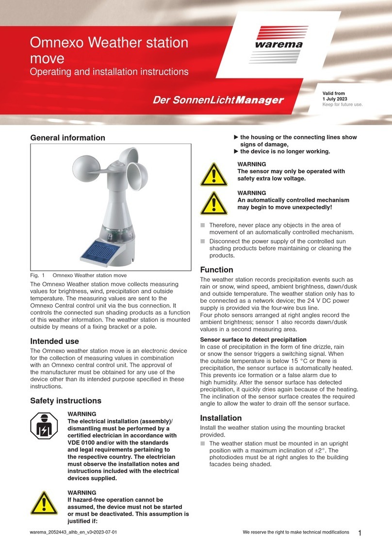
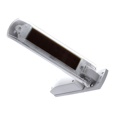
WAREMA Weather station User manual

890013_f•en•2015-11-01 We reserve the right to carry out improvements 1
Operating and installation instructions
Weather station for WAREMA climatronic®
Keep for future use.
Valid from 01 July 2013
WARNING
If hazard-free operation cannot be as-
sumed, the device may not be started or
must be deactivated. This assumption is
justified
If the housing or the supply lines show signs
of damage,
The device is no longer working.
WARNING
The sensor may only be operated with
safety extra low voltage.
WARNING
It is important to comply with the follow-
ing instructions in the interest of personal
safety.
■Do not allow children to play with the operating elements
of the control or remote control. Store the remote controls
out of reach of children!
■Make sure that no persons or objects are in the range of
movement of the driven parts (blinds, window, etc.).
■Disconnect the product from the supply voltage if clean-
ing or other maintenance work must be performed!
Function
The weather station records precipitation events such as
rain or snow, wind speed and direction, ambient bright-
ness and dawn/dusk, and receives the radio time tele-
gram. The weather station only needs to be connected as
a network station; the 24 V DC voltage supply is provided
via a 4-wire bus cable.
Radio clock reception
The weather station receives the DCF77 time telegram,
transmitted by radio, with the built-in radio clock receiver
and provides it to the internal real-time clock in the control
panel.
Rooflight opening for brightness measurement
Four photo sensors arranged at right angles record the
ambient brightness whereby sensor 1 also records dawn/
dusk values in a second measuring area.
Sensor surface to detect precipitation
A switch signal is triggered by the sensor in the event of
precipitation in the form of drizzle, rain or snow. The sen-
sor surface can be heated. If the outside temperature falls
below +15 °C or precipitation is registered, the heater is
activated and thereby prevents triggering due to high rela-
tive humidity alone or ice formation at negative tempera-
tures. After the sensor surface has detected precipitation,
it quickly dries again because of the heating.
General information
5
6
7
1
2
8
3
4
9
9
10
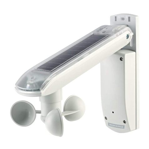
Fig. 1 Weather station
1 "Photo" and "dawn/dusk" sensor
2 Sensor surface for "precipitation" sensor
3 Opening for "wind speed" and "wind direction" sensor
4 Terminal cover and cable entry
5 Base plate
6 Cable guide
7 Joint
8 Routing of the connection line, e.g. 4x AWG26C UL bl
9 Cable ties for mast mounting, screws and nuts for pole
mounting (included)
10 Status LED
Intended use
The device has been developed for the collection of
measurement values in conjunction with a WAREMA
climatronic. The approval of the manufacturer must be
obtained for uses outside of the purposes listed in these
instructions.
Safety instructions
WARNING
The electrical installation must be per-
formed by a certified electrician in accord-
ance with the electrical installation regu-
lations published by the Association of
German Electrical Engineers (VDE 0100)
or the standards and regulations of the
country. The specialist must observe the
installation instructions included with the
electrical device.

890013_f•en•2015-11-01We reserve the right to carry out improvements
2
The inclination of the sensor surface creates the required
angle to allow the water to drain off the sensor surface.
Openings to record wind
Four openings with sensors, arranged at right angles,
record the wind speed. The direction of the wind is deter-
mined by calculating the difference in the sensor values.
Installation
Use the included mounting hardware to mount the weather
station.
■The weather station must be mounted in an upright
position with a maximum inclination of ±2°. The photo-
diodes must be at right angles to the building facades
being shaded. Position photodiode 1 to face as north-
ward as possible.
■The weather station should be mounted easily acces-
sible on the highest point of the roof structure or the
conservatory. To prevent interference with the wind
evaluation, do not mount the device away from the
wind.
■For the system to function properly, precipitation must
be able to hit the sensor surface from any direction
without interference.
■The supply line must be routed so that water cannot
enter into the housing (see Fig. 1). Use weather-resist-
ant (suitable for outdoor installation) cables such as
4x AWG26C UL bl!
■The photodiode 1 controls the dawn/dusk control (see
Fig. 2). The weather station should therefore be posi-
tioned so that the photodiode cannot be influenced at
night by street or garden lighting or other external light
sources (e.g. flashlights).
■Metal-clad buildings, domestic interference sources
(unshielded household appliances, television sets,
computers), supply lines and metallic objects such as
sheet metal enclosures, must have a distance of at
least 0.5 m from the sensor. Check the radio clock re-
ception prior to final installation.
Trees, bushes or parts of the building can shade the
sensor during the course of the day. In this case, the
sensor cannot deliver exact values and the results will
be incorrect. Therefore, select the installation location
carefully.
Assignment of the photodiodes
The numbers 1 to 4 have been factory-assigned to the
four photodiodes; see Fig. 2.
Photo 1
(Dusk)
Photo 3
Photo 4 Photo 2
Fig. 2 Alignment of the photodiodes
Installation options
Fig. 3 Wall mounting
Fig. 4 Ceiling mounting
Fig. 5 Roof mounting / Standpipe mounting

3
890013_f•en•2015-11-01 We reserve the right to carry out improvements
Fig. 6 Pole mounting: Make sure that the cable ties are guided
through the slots and that the projections of the locking
closures point outward.
Electrical installation
An on-site overload current protection device (fuse) and a
disconnecting and isolating switch to switch off the entire
system must be provided.
The device meets the EMC directives for use in residential
and commercial areas.
When performing the electrical installation, please note the
following:
The max. bus line length between the first and last bus
device must not exceed 1200mm.
Repeaters/HUBs are needed for longer line lengths.
A line structure must be adhered to. Branch lines are
only possible with repeaters or HUBs!
Please take out the ID labels WAREMA ID from the devices
and give them to your system integrator (see also
page4). A clear allocation of the devices and ID labels
must be ensured!
The bus lines must be provided with terminating resis-
tors at the beginning and end of the line.
Commissioning
To be able to commission the weather station, it must be
set up and identified in the WAREMA climatronic control
panel. This is performed either in the assistant or manually
(see installation instructions art. no. 2003 869). To identify
the device (determining the serial number), place the sup-
plied magnet on the type plate at the right outside surface
of the housing until the status LED lights up for confirmati-
on (see Fig. 8). Alternatively, you can enter the serial num-
ber manually in the operating unit.
Cleaning
The weather station must be cleaned every 3 months.
■Clean the device with a soft damp cloth. Steam or
high-pressure cleaners, abrasive sponges, abrasive
agents, and solvents such as alcohol or benzine may
not be used.
■The openings for the wind measurement may only be
blown through. Never insert sharp objects.
Maintenance
There are no parts within the device that require mainte-
nance.
Liability
Failure to comply with the product information in these
instructions and use of the unit in a manner that contra-
venes its intended use and purpose may result in the
manufacture refusing to honour warranty claims for prod-
uct damage. In this case, liability for consequential harm
to persons or damage to property will also be excluded.
Follow the instructions in the operating instructions of your
sun shading system. The automatic or manual operation
of the sun shading system when it is iced over, and use of
the sun shading system during severe weather, may cause
damage and must be prevented by the user by taking suit-
able precautions.
Disposal
After its use, the device must be disposed off according to
legal regulations or returned to your local recycling centre.
Technical data
Weather station Min. Typ. Max. Unit
Supply
Operating voltage (SELV) 20 24 28 V
DC
Current consumption 92 160 250 mA
Temperature sensor
Measuring range -30 +60 °C
Resolution 0.5 °C
Accuracy ±0.5 °C
4 direction-dependent photo sensors
Measuring range 0 100 kLx
Resolution during daytime 1 kLx
Accuracy during daytime 1 kLx
Resolution at dawn/dusk 2 Lx
Accuracy at dawn/dusk 10 Lx
Wind speed
Measuring range 0 25 m/s
Resolution 1 m/s
Accuracy ±1 m/s
Wind direction
Measuring range 0 360 °
Accuracy 45 °
Radio clock reception
Frequency 77.5 kHz
Precipitation sensor
Surface temperature of the
sensor surface when heated
40 °C
Dimensions
WxHxD 84x140x160 mm
Installation
Wall/ceiling/pole
Degree of protection/safety class
Degree of protection IP 43
Safety class III

890013_f•en•2015-11-01We reserve the right to carry out improvements
4
1234
Weather station
Onsite
junction box
from
previous bus device
JY(St)Y 2x2x0.8mm ø
X1
J1
Bus B
0V
A
B
24V
Bus A
24 V
0 V
4xAWG 26C UL black
Network
closed (120Ω)
Network open
Terminal strip J1
Fig. 8 Connection example of the weather station
Weather station Min. Typ. Max. Unit
Test standards
Product standard:
EMC basic standards:
DIN EN 60730-1: 2002-1
DIN EN 61000-6-2: 2002-8
DIN EN 61000-6-3: 2002-8
DIN EN 50366: 2003-11
Miscellaneous
Software class A
Conformity Specified under
www.warema.de
Ambient conditions
Operating and storage tem-
perature
-30 20 +60 °C
Rel. humidity
(non-condensing)
10 40 100 %RH
Article numbers
Weather station 1002662
Accessory box 1002022
WAREMA Renkhoff SE
Hans-Wilhelm-Renkhoff-Strasse 2
97828 Marktheidenfeld
Identify the weather station, if this
is required by the menu, by holding
the supplied magnet against the
type label on the right-hand side
(as seen from the front).
-> The status LED lights up
as a confirmation.
Status-LED
Magnet
The feed line may not hang below
this height to avoid hindering the
wind sensors. It may not be located
in line with a sensor opening.
(Covered)
type label
Fig. 7 Identification of the weather station (using a magnet)
Keep in a safe place for use during commissioning!
Affix the ID label of the weather station here.
00001372 Wetterstation
Note down the installation location here.
Table of contents
Other WAREMA Weather Station manuals
Popular Weather Station manuals by other brands

La Crosse Technology
La Crosse Technology WS-1611T Operation manual

Bresser
Bresser Quadro-NG-Thermo-Hygro instruction manual

La Crosse Technology
La Crosse Technology C79790-11 manual

Levenhuk
Levenhuk Wezzer BASE L80 user manual

Oregon Scientific
Oregon Scientific BAR686 user manual

Davis Instruments
Davis Instruments Vantage VUE Quick reference guide