Hansford sensors HS-517 User manual
Vibration Monitoring For Industrial Applications
www.hansfordsensors.com
© 2021 Hansford Sensors
User Manual
HS-517
Vibration Trip Display

HS-XXX User Manual
QM039 Issue 1
HS-517
Vibration Trip Display
User Manual
Hansford Sensors Ltd.
This document may not be reproduced in any way without the prior written
permission of the company.
HS-517 User Manual

QM039 Issue 1
1. General and Safety-Related Information
1.1 Symbols Used
1.2 Staff Qualification
1.3 Intended use
1.4 Foreseeable misuse
1.5 Limitation of liability and warranty
1.6 Safe handling
1.7 Safety-related maximum values
1.8 Scope of delivery
2. Product Identification
3. Mounting
3.1 Mounting and safety instructions
3.2 Mounting steps for M12x1 connectors
3.3 Positioning of the display module
4. Electrical Connection
4.1 Connection and safety instructions
4.2 Conditions for the explosion-hazardous area
4.3 Electrical installation
5. Commissioning
6. Operation
6.1 Control and display elements
6.2 Configuration
6.3 Password system
6.4 Unit
6.5 Explanation of hysteresis and compare mode
6.6 Menu system structure
6.7 Menu list
7. Maintenance
8. Removal from service
9. Service/repair
10. Disposal
11. Warranty terms
12. EU Declaration of conformity
3
Contents
HS-517 User Manual
4
4
5
6
6
6
6
6
7
8
8
9
9
10
10
11
14
15
15
15
16
17
17
17
18
19
21
21
22
22
23
23-24

1. General and Safety-Related Information on this Operating Manual
This operating manual enables safe and proper handling of the product, and forms part
of the device. It should be kept in close proximity to the place of use, accessible for staff
members at any time.
All persons entrusted with the mounting, installation, putting into service, operation,
maintenance, removal from service, and disposal of the device must have read and
understood the operating manual and in particular the safety-related information.
The following documents are an important part of the operating manual:
-datasheet
-type-examination certificate
For specific data on the individual device, please refer to the respective data sheet.
Download these by accessing www.hansfordsensors.com or request them:
[email protected] | phone.: +44 (0) 845 680 1957
The IS versions of our products are variants of the standard products.
In addition, the applicable accident prevention regulations, safety requirements,
and country-specific installation standards as well as the accepted engineering
standards must be observed.
For the installation, maintenance and cleaning of the device, the relevant regulations
and provisions on explosion protection as well as the accident prevention regulations
must absolutely be observed.
The device was designed by applying the following standards:
-EN IEC 60079-0:2018
-EN 60079-11:2012
HS-517 User Manual
QM039 Issue 1 - 3-

HS-517 User Manual
QM039 Issue 1
1.1 Symbols Used
Warning word Meaning
DANGER
-Imminent danger!
-Non-compliance will result in
death or serious injury.
WARNING
-Possible danger!
-Non-compliance may result in
death or serious injury.
CAUTION
-Hazardous situation!
-Non-compliance may result in
minor or moderate injury.
NOTE - draws attention to a possibly hazardous situation that
may result in property damage in case of non-compliance.
Precondition of an action
-Type and source of danger
-Measures to avoid the danger.
Warning word
1.2 Staff qualification
Qualified persons are persons that are familiar with the mounting, installation,
putting into service, operation, maintenance, removal from service, and disposal of
the product and have the appropriate qualification for their activity.
This includes persons that meet at least one of the following three requirements:
-
-
They know the safety concepts of metrology and automation technology and
are familiar therewith as project staff.
They are operating staff of the measuring and automation systems and have
been instructed in the handling of the systems. They are familiar with the
operation of the devices and technologies described in this documentation.
-They are commissioning specialists or are employed in the service
department and have completed training that qualifies them for the repair of
the system. In addition, they are authorized to put into operation, to ground,
and to mark circuits and devices according to the safety engineering
standards.
All work with this product must be carried out by qualified persons!
- 4-

QM039 Issue 1
1.3 Intended use
The HS-517 vibration trip display is designed to indicate measurement
values on a build in LED display and is optionally equipped with
a Relay (with PNP open collector output). ). It is designed to be used
with Vibration Transmitters HS-420I and HS-422I Series with 4...20mA /
2-wire analogue output. The HS-517 may be used with all transmitters if the
following requirements are met:
•output signal of the transmitter: 4 … 20 mA / 2-wire
•suitable electrical connection (according to data sheet)
The digital vibration trip display HS-517 has to be mounted between
the connector and transmitter and is ready for immediate operation. No
additional supply is required, the display is supplied by the 4 … 20 mA circuit. A
preferred application is on-site process monitoring in combination with the HS-420I
or HS-422I Series.
Programming is performed via two buttons on the front side. The following
parameters can be set: scaling, decimal point, damping, switch point, and delay.
Moreover, a min./max. value memory is available. The settings will be retained
even in case of a power failure. Incidences of range exceedance in both directions
can be displayed as messages. The integrated diagnostic system constantly
monitors all functions of the display. The housing can be turned by 300° in an
infinitely variable manner, the display by 330°.
This operating manual applies to devices with explosion protection approval and is
intended for the use in IS-areas. A device has an explosion-protection approval if this
was specified in the purchase order and confirmed in our order acknowledgement. In
addition, the manufacturing label includes a sign.
The user must check whether the device is suited for the selected use. In case
of doubt, please contact our sales department: [email protected] | phone:
+44 (0) 845 680 1957
Hansford Sensors assumes no liability for any wrong selection and the consequences
thereof!
The technical data listed in the current data sheet are engaging and must absolutely
be complied with. If the data sheet is not available, please order or download it from
our homepage: www.hansfordsensors.com
WARNING
Danger through incorrect use
-In order to avoid accidents, use the
device only in accordance with its
intended use.
HS-517 User Manual
- 5-

HS-517 User Manual
QM039 Issue 1
1.4 Foreseeable misuse
The digital plug-on display HS-517 must not be used particularly in the following
cases:
In areas for which the device has no approval. When the HS-517 is used in
combination with other devices, the approval of the device with the lowest approved
area applies.
1.5 Limitation of liability and warranty
Failure to observe the instructions or technical regulations, improper use and use not
as intended, and alteration of or damage to the device will result in the forfeiture of
warranty and liability claims.
1.6 Safe handling
NOTE - Do not use any force when installing the device to prevent damage of the
device and the plant!
NOTE - Treat the device with care both in the packed and unpacked condition!
NOTE - The device must not be altered or modified in any way.
NOTE - Do not throw or drop the device!
NOTE - Excessive dust accumulation (over 5 mm) and complete coverage with
dust must be prevented!
NOTE - The device is state-of-the-art and is operationally reliable. Residual hazards
may originate from the device if it is used or operated improperly.
1.7 Safety-related maximum values
1.8 Scope of delivery
Check that all parts listed in the scope of delivery are included free of damage, and
have been delivered according to your purchase order:
-Vibration trip display HS-517
- sheet of unit labels
- operating manual
- 6 -
Permissible temperatures for environment: -25 ... 70 °C
Ui = 28 V, Ii = 93 mA, Pi = 660 mW, Ci ≈ 0 nF, Li ≈ 0 µH
plus cable inductivities 1 µH/m and
cable capacities 100 pF/m (for cable by factory)
QM039 Issue 1
2. Product identification
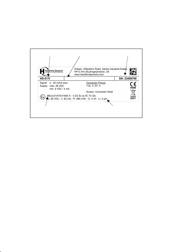
The device can be identified by means of the manufacturing label with order code.
The most important data can be gathered therefrom. The version of the firmware,
(e. g. P07) will appear for about 1 second in the display after starting up the
device. Please hold it ready for inquiry calls.
HS-517 User Manual
Fig. 1: Example of manufacturing label
NOTE - The manufacturing label must not be removed!
The marking for devices with explosion-protection approval has to include
following information:
AX 14: EC-type examination certificate IBExU21ATEX1064 X
Ex-designation: II 2G Ex ia IIC T4 Gb
EC-type examination certificate no.,
explosion marking
Type designation Ordering code Serial number
Safety technical
maximum values
- 7-

HS-517 User Manual
QM039 Issue 1
3. Mounting
3.1 Mounting and safety instructions
DANGER
Danger of death from explosion, airborne
parts, leaking fluid, electric shock
-Always mount the device in a depressurized
and de-energized condition!
-Do not install the device while there is a risk of
explosion.
DANGER
Danger of death from improper installation
- Installation must be performed only by
appropriately qualified persons who have
read and understood the user manual.
NOTE - The technical data listed in the EC type-examination certificate are
binding. Download these by accessing
www.hansfordsensors.com or request them by email or phone
[email protected] | phone.: +44 (0) 845 680 1957
NOTE - Make sure that the entire interconnection of intrinsically safe components
remains intrinsically safe. The owner-operator is responsible for the intrinsic safety
of the overall system (entire circuitry).
NOTE - Make sure that an equipotential bonding is in place for the entire course
of the line, both inside and outside the intrinsic area.
NOTE - The external circuit must prevent an external power-in-flow to the
contacts. Suitable signal separating devices which fulfil this demand have to be
used.
NOTE - If there is increased risk of damage to the device by lightning strike or
overvoltage, increased lightning protection must additionally be provided!
NOTE - Do not remove the packaging of the device until shortly before the
mounting procedure in order to exclude any damage! Dispose of the packaging
properly!
NOTE - The display and the plastic housing are equipped with a rotation
limiters. Please do not attempt to overtighten it by applying increased force.
- 8 -

QM039 Issue 1
1. Plug the vibration trip display onto the transmitter.
2. Plug the cable socket or mating plug onto the HS-517 and fasten it properly.
3.3 Positioning of the display module
In order to ensure easy readability even when the device is installed in an
awkward location, the display can be rotated into the desired position. Its
rotational capability is illustrated below. Note rotation limits.
3.2 Mounting steps for M12x1 connectors
HS-517 User Manual
Fig. 2 Display module (example with M12x1)
- 9 -

HS-517 User Manual
QM039 Issue 1
DANGER
Danger of death from electric shock or
explosion
-Explosion hazard if the operating voltage is too
high (max. 28 VDC).
-Always mount the device in a depressurized and
de-energized condition!
-
-
Do not install the device while there is a risk of
explosion.
Operate the device only within the specification!
(according data sheet and EC-type examination
certificate)
The limit values listed in the EC type-examination certificate are
observed. (Capacity and inductance of the connection cable are not
included in the values.)
The supply corresponds to protection class III (protective insulation).
NOTE - If the device is equipped with a cable socket it must be ensured that the
external diameter of the used cable is within the permissible clamping range.
Moreover you have to ensure that it lies in the cable gland firmly and cleftlessly!
NOTE - Use a shielded and twisted multicore cable for the electrical connection.
4. Electrical connection
4.1 Connection and safety instructions
- 10-
Intrinsically safe area
Contact
Trasmitter Display
Supply
24 VDC
Contact
+ UB
- UB
UB
+ VS
- VS
+ UB
- UB
HS-517
QM039 Issue 1
4.2 Conditions for the explosion-hazardous area Danger generated by
electrostatic charging
DANGER
Danger of death from explosion
-Explosion hazard due to spark formation from
electrostatic charging of plastic components.
-If devices are equipped with a cable outlet, the
connection cable routing must be fixed.
-Do not clean the device and, if applicable, the
connection cable, in a dry state! Use a moist cloth, for
example.
Overvoltage protection
If the device is used as electrical equipment of category 1 G, a suitable
overvoltage protection device must be connected in series (attend the valid
regulations for operating safety as well as EN60079-14).
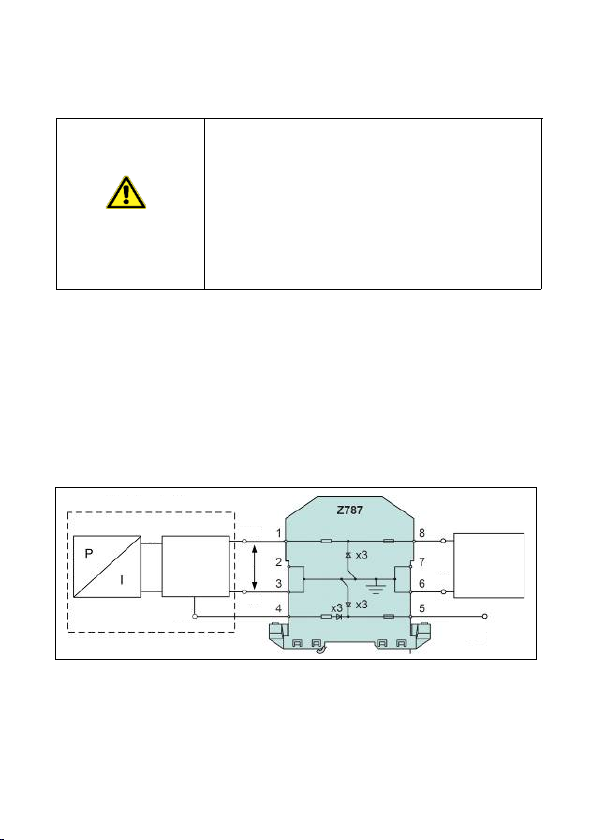
Schematic circuit design
The operation of an intrinsically safe device in intrinsic safe areas requires special
care when selecting the necessary Zener barrier or transmitter repeater devices to
be able to use the device’s characteristics to the full extent. The following diagram
shows a typical arrangement of power supply, Zener barrier and plug-on display.
HS-517 User Manual
Fig. 3 : circuit diagram
- 11-

QM039 Issue 1
NOTE - Observe item (17) of the type-examination certificate which specifies
special conditions for intrinsically safe operation.
Exemplary circuit description
The supply voltage of e. g. 24 VDC provided by the power supply is led across the
Zener barrier. The Zener barrier contains series resistances and Zener diodes as
protective components. Subsequently, the operating voltage is applied to the
device and, depending on the pressure, a particular signal current will flow.
Selection criteria for Zener barriers and galvanic power supply
The minimum supply voltage V
S
min of the device must not fall short.
When using a galvanically insulated amplifier with a linear bonding, please attend
that the terminal voltage of the device will decrease like it does with a Zener
barrier. Furthermore, account must be taken of the fact that a certain voltage drop
will also occur on an optionally used signal isolation amplifier, whereby the
operating voltage of the device will decrease additionally.
Test criteria for the selection of the Zener barrier
In order not to fall below VS min, it is important to verify which minimum supply
voltage is available at full level control of the device.
The technical data of the barrier will usually provide the information needed for
the selection of the Zener barrier. However, the value can also be calculated. If a
minimum supply voltage of e.g. 16 V is assumed, a certain voltage drop on the
series resistor of the Zener barrier follows in accordance with Ohm’s law. If the
contact is additionally activated on a device with PNP switch output, the additional
current flowing from the contact to the load resistor will also flow through the
Zener barrier or from the output of a galvanic power supply. The higher the load
current, the lower the available minimum operating voltage. In the circuit shown,
the maximum current can be calculated from the maximum voltage difference (Vab
barrier max) between input and output of the Zener barrier divided by the series
resistance of the Zener barrier. The maximum signal current must be subtracted
from this value. If the available residual current is smaller than the current
required at the contact, either a different barrier or a higher supply voltage before
the barrier should be chosen.
NOTE - When selecting the power supply, the maximum operating conditions
according to the EC type-examination certificate must be observed. When
assessing the power supply, please refer to their current data sheets to ensure
that the entire inter-connection of intrinsically safe components will remain
intrinsically safe.
HS-517 User Manual
- 12-

QM039 Issue 1
HS-517 User Manual
Calculation example for the selection of the Zener barrier
The nominal voltage of the power supply in front of the Zener barrier is 24 VDC ± 2%.
This results in:
- greatest supply voltage: VSup max = 24 V * 1.02 = 24.48 V
- smallest supply voltage: VSup min = 24 V * 0.98 = 23.52 V
First, the minimum supply voltage of the combination of plug-on display and transmitter
must be determined. This results from the minimum supply voltage of the transmitter
plus the voltage drop of the plug-on display which is nominally 6 V. For example, UB
transmitter min = 10 V results in a minimum supply voltage
VB min = 16 V.
The series resistor of the Zener barrier is specified with 295 Ω. The maximum voltage
drop at the Zener barrier may reach the following value:
Vab barrier max = 23.52 V – 16 V = 7.52 V
In order for this condition to be adhered to, the maximum current must not exceed the
following value:
Imax = 7.52 V : 295 Ω = 25.49 mA
The maximum current of the combination of plug-on display and transmitter is made up
of the sum of signal current and switching current. There are two approaches:
1. The measuring range is to be utilized in the range of
0 … 100 %. A maximum signal current of 20 mA is generated thereby. Based on
the facts above, the available residual current through the switch output is
calculated as follows:
IResid 1 = 25.49 mA – 20 mA = 5.49 mA
2. With an analogue output of 4 ... 20 mA, the measuring range is to be utilized only
in a specific range, e.g.
0 … 70 %. This results in a maximum signal current:
ISignal max = ∆i * 0.7 + iOffset = 16 mA * 0.7 + 4 mA = 15.2 mA (with ∆i = 20 mA – 4
mA and iOffset = 4 mA)
Here, the available residual current through the switch output is:
IResid 2 = 25.49 mA – 15.2 mA = 10.29 mA
Condition: IResid ≥ ISwitch output
The switching current (current through the switch output) must not exceed the
determined residual current since this will impair the functionality of the device.
NOTE - The switching current must be determined separately by the user as it
depends on the particular case of application. The switching current can be calculated
or measured at the switch output.
NOTE - Please note that no line resistances have been listed in this calculation.
These lead additionally to a voltage drop that must be taken into account.
- 13-
QM039 Issue 1
HS-517 User Manual
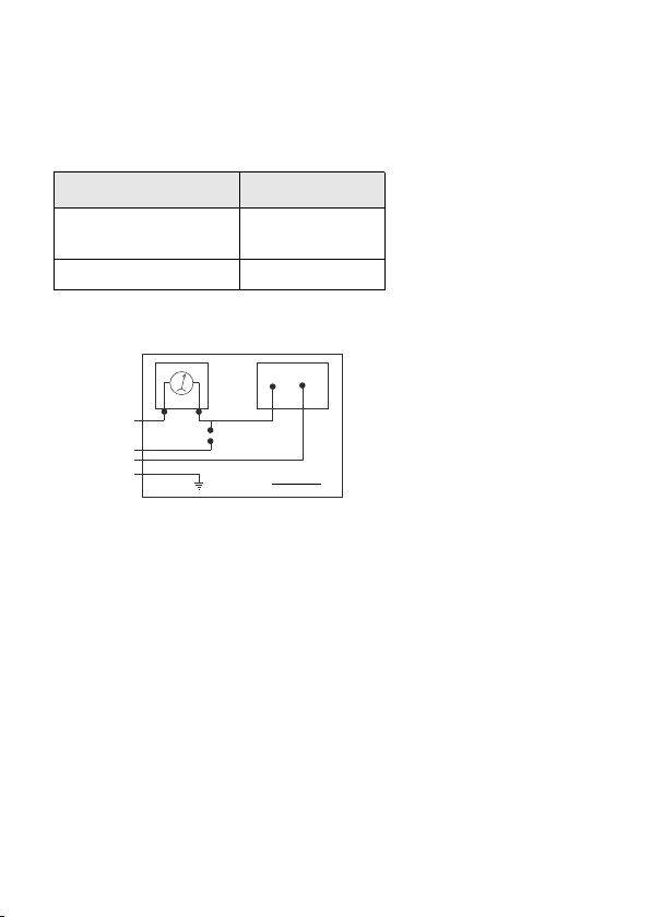
4.3 Electrical installation
Connect the device electrically according to the information specified on the
type plate, the following table, and the connection circuit diagram.
Pin configuration:
Electrical
connections
M12x1, metal
(5-pin)
Supply +
Supply −
Relay 1
2
4
1
Screen Screen to case
Wiring diagram:
Voltage supply
The voltage drop generated by the device electronics is approx. 6 VDC. Consider this
when designing your system supply. The limit values of the voltage supply are
calculated as follows:
minimum operating voltage: maximum
operating voltage:
VS min = Vtransmitter min + 6 V VS max =
Vtransmitter max + 6 V
Vtransmitter min = minimum operating voltage of the 2-wire transmitter used
Vtransmitter max = maximum operating voltage of the 2-wire transmitter used
- 14 -
Pin 1 (Brown)
Pin 4 (Black)
4-20mA Power Supply
0V +
+ -
Pin 2 (White)
Switch to DI
Screen to case
Earth PLC/DCS

QF056 Issue 1 Release
Customer Recalibration Log Sheet for HS-620 & HS-630 Vibration Meter Kits
Z:\Engineering\QF056 (Customer Calibration log)
1. Remove the inapplicable model number from the Model No. line in calibration sheet below (HS-620/630).
2. Print out a colour copy of this page.
3. Enter the Serial number, sign the calibrated by and date the date of calibration.
4. Cut out the certificate of calibration and include this with the items.
5. Commissioning
DANGER
Danger of death from explosion
-
-
Explosion hazard if the operating voltage is too high
(max. 28 VDC)!
Operate the device only within the specification!
(according to data sheet and EC type-examination
certificate)
The device has been installed properly.
The device does not have any visible defect.
HS-517 User Manual
QM039 Issue 1 - 15-
6. Operation
6.1 Control and display elements
Fig. 5 touchpad
The device has (when configured) one LED which is allocated to the Relay. The
LED will light up when the set point has been reached and the contact is active.
The display of the measured value as well as the configuration of the individual
parameters occurs menu-driven via the seven-segment display.
LED
Relay 1
4-digit seven-
segment display
▼-button ▲-
button
QM039 Issue 1
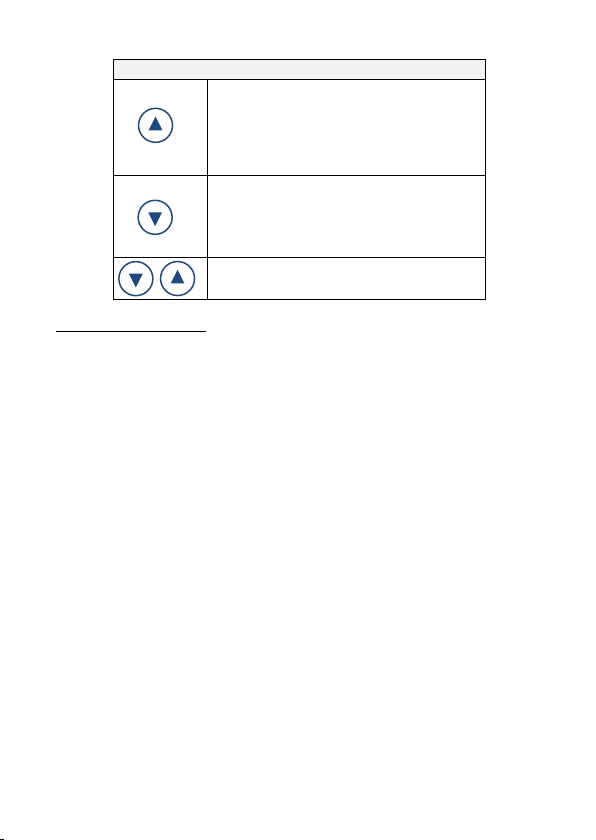
Button functions
•move forward in the menu system
(beginning with menu 1)
•increase the displayed value
note: increase the counting speed by
keeping the button pushed for more than
5 second
•move backwards in the menu system
(beginning with the last menu)
•decrease the displayed value
note: increase the counting speed: keep
the button pushed for more than 5 second
confirm the menu items and set values by
pushing both buttons simultaneously
HS-517 User Manual
execution of configuration:
- set the desired menu item by pushing the ▲- or ▼-button
-activate the set menu item by pushing both buttons simultaneously
-
-
set the desired value or select one of the offered settings by using the ▲- or ▼-
button
store / confirm the set value/selected setting and exit the menu by pushing both
buttons simultaneously
- 16-
6.2 Configuration
The menu system is a closed system allowing you to scroll both forward and backward
through the individual set-up menus to navigate to the desired setting item. All settings
are permanently stored in an EEPROM and therefore available again even after
disconnecting from the supply voltage. The structure of the menu system is the same
for all types of devices, regardless of the number of contacts. However, they only differ
by the number of menus. Following figure and the menu list shows all possible menus.
Please follow the manual meticulously and remember that changes of the adjustable
parameters (switch-on point, switch-off point, etc.) become only effective after pushing
both buttons simultaneously and leaving the menu item.

QM039 Issue 1
HS-517 User Manual
6.3 Password system
The device can be locked in order to prevent configuration by unauthorized
persons. Refer to menu 1 of the menu list for more information.
6.4 Unit
The unit of the measured value is already determined at the time of ordering by
the desired measuring range. However, the device may also be labelled with
another unit at a later time by attaching one of the supplied unit labels.
6.5 Explanation of hysteresis and compare mode
In order to invert the respective mode, the values for switch-on and switch-off
points must be exchanged.
- 17 -
Fig. 5: Compare mode Fig. 6: Compare mode inverted
Fig. 7: Hysteresis mode Fig. 8: Hysteresis mode inverted

QM039 Issue 1
HS-517 User Manual
6.6 Menu system structure
Display mode
(measured value
is displayed)
Access protection/
entry to special
menus
Menu 1:
PAon / PAof
Special menu 1:
Full scale set
FS S
Code-No.: 0238
Measured value
update (display)
Menu 14: dLdS
Minimum value
Menu 13: LoPr
Zero point
Menu 3: ZP
Hysteresis- and
compare mode
Menu 9:
HY 1 / CP 1
End point
Menu 4: EP
Damping
Menu 5: FILt
Exceeding
message
Menu 6: HILo
Switch-on point S1
Menu 7: S1on
Switch-off point S1
Menu 8: S1of
Switch-on delay S1
Menu 10: d1on
Switch-off delay S1
Menu 11: d1off
Maximum value
Menu 12: HIPr
PA of -
Password inactive
Decimal position
Menu 2: dP
PA on -
Password active
Special menu 2:
Offset set
oF S
Code-No.: 0247
Special menu 3:
Defaults
LoAd
Code-No.:0729
Special menu 4:
Password
SEtP
Code-No.: 0835
- 18-
HS-517 User Manual
QM039 Issue 1
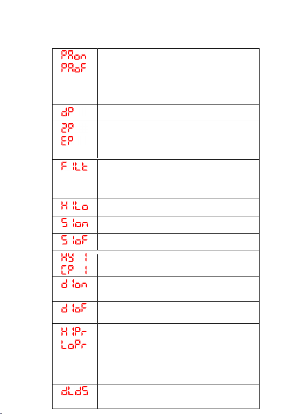
6.7 Menu list
button functions are well known (see ″7.1 Control and display
elements″)
menu 1 – access protection
PAon password active
to deactivate: set password
PAof password inactive
to activate: set password
default setting for the password is "0005"; modification
of the password is described in special menu 4
menu 2 – set decimal point position
menus 3 and 4 – set zero point / end point
the device has been configured correctly before
delivery, so a later setting is only necessary, if a
differing displayed value is desired
(e. g. 0 ... 100 %)
menu 5 – set damping
this function allows getting a constant display value
although the measuring values may vary
considerably; the time constant for a simulated low-
pass filter can be set (0.3 up to 30 sec permissible)
menu 6 – exceeding message
set "on" or "off"
menus 7 – set switch-on point
set the values, for the activation of contact 1
menus 8 – set switch-off point
set the values, for the deactivation of contact 1
menus 9 – select hysteresis or compare mode
select hysteresis mode (HY 1) or compare mode
(CP 1) for contact 1
menus 10 – set switch-on delay
set the value of the switch-on delay after reaching
contact 1 (0 up to 100 sec permissible)
menus 11 – set switch-off delay
set the value of the delay after reaching switch-off
point 1 (0 up to 100 sec permissible)
menus 12 and 13 – maximum / minimum
pressure display
view high pressure (HIPr) or low pressure (LoPr)
during the measurement process
(the value will not remain stored if the power supply
is interrupted)
to delete: push both buttons again within one
second
menu 14 – measured value update (display)
set the length of the update cycles for the display
(0.0 up to 10 sec permissible)
-19 -
Table of contents


