Hanyoung HYP-8R1.5 User manual

MK0201E050512
Before you use, read safety precautions carefully, and use this product properly.
The precautions described in this manual contains important contents related with
safety; therefore, please follow the instructions ,accordingly. The precautions are
composed of DANGER, WARNING and CAUTION.
Do not touch or contact the input/output terminals because they may cause
electric shock.
Since this product is not designed as a safely used device the user must install
double safety equipment when this product is used for equipment with possible
fatal accident or large property damage.
1. Pay attention that it is possible to damage a proximity sensor by a short circuit
when wiring load.
2. Wiring to an applicable device shall be certainly connected by using
compressing terminals or soldering.
3. Do not use PNP type or NPN type indiscriminately.
4. Please wire after ensuring whether input conditions are accepted to an
applicable device.
5. When there is a power or high voltage line close to the cord of the proximity
sensor, wire the cord with shielding such as an independent metal conduit to
prevent against proximity sensor’s damage or malfunction.
6. Although the proximity sensor has a surge absorption circuit, if there is any
machine that has a large surging one (e.g., a motor, welding machine, etc)
near the proximity sensor, connect a varistor, surge absorber, noise filter to a
surge generating area.
7. Effect of Consumption Current: When AC type of proximity sensor is OFF, the
proximity sensor has little consumption current for an operation of the circuit.
Because of this fact, the little voltage left in the load may be a cause of load
reset defective, so please make sure this voltage is less than the load reset
voltage before using.
8. In case of a load current is small: When a loaded current of AC type of
proximity sensor is less than 5 mA, wire a bleeder resistor with the load in
parallel so that make the residual voltage of the proximity sensor be less than
the loaded reset voltage.
9. Make the ripple content of the rated voltage which supplied into DC (NPN,
PNP) type of proximity sensor be less than the maximum 10 % of the
ripple content.
10. In case of using a condenser as a load, wire a current-limiting resistor in
series so that set the peak current shall be within the loaded current of the
proximity sensor.
11. In case of an inductive load (e.g., a motor, relay, magnet, etc), connect the
load with surge absorbing diode in parallel.
12. Pay attention at a position of attachment, divergence, slack and distortion of a
sensing surface or proximity sensor.
13. In the place of possibly occurring metal particles, make sure whether a
sensing distance is properly working since it can be affected if metal particles
stick to the sensing surface.
14. Pay attention on using or storing the proximity sensor outdoors.
15. Do not use the proximity sensor in an environment with chemical, solvent or
corrosive.
16. Please avoid as much as possible to put the proximity sensor in hot water or
to use them in a place where generates high pressure steam.
17. The contents of this manual may be changed without prior notification.
If you do not follow the contents described in the safety information then it is
possible to be a cause of the product’s malfunction so please follow them.
Safety information
Ratings
WARNING
CAUTION
DANGER
HEAD OFFICE
1381-3, Juan-Dong, Nam-Gu Incheon, Korea
TEL:(82-32)876-4697 FAX:(82-32)876-4696
Inductive Proximity Sensor
Round Type
We appreciate you for purchasing HanYoung NUX Co.,Ltd
product. Before using the product you have purchased, check
to make sure that it is exactly what you ordered. Then, please
use it following the instructions below.
MAIN PRODUCTS
- DIGITAL : Temperature Controller, Counter, Timer,Speedmeter,
Tachometer, Panel Meter, Recorder
- SENSOR : Proximity Sensor/Photo Electric Sensor,
Rotary Encoder, Optical Fiber Sensor,
Pressure Sensor
- ANALOG : Timer, Temperature Controller
Type
Model Name
Sensing Distance
Setting Distance
Response Frequency
Standard Sensing Target
(mm)
Hysteresis
Rated Voltage
Control Output
Residual Voltage
Leakage Current in Output
Operation Indicator
Protection Circuit
Operating Ambient Temperature
Operating Ambient Humidity
Case Protection
Vibration Resistance
Dielectric Strength
Shock Resistance
Insulation Resistance
Material
DC Power Source Type 2-WIRE DC Power Source Type AC Power Source TYPE
12 ~ 24 V DC ( 10 %)
Resistive Loaded Current: below Max. 200 mA,
Inductive Loaded Current: below Max. 100 mA
Below 1 V (Using Rated Voltage : 24 V DC,
Resistive Load:Max. 200 mA)
Below 0.5 mA (Using Rated Voltage : 12 V DC)
Below 1.5 V
24 V DC ( 10 %)
Resistive Loaded Current: below Max. 50 mA,
Inductive Loaded Current: below Max. 25 mA
Below 7 V (Using Rated Voltage : 24 V DC,
Resistive Load : Max. 50 mA)
Below 1 mA (Using Rated Voltage : 12 V DC)
100 ~ 240 V AC (Rated Voltage 10 %)
Loaded Current: below Maximum 200 mA
Below 20 V DC
Below 2.2 mA
Max 10 % of Sensing distance
Within Circuit Protection from reversed power supply connection, Surge Protection Circuit, Overcurrent circuit protection (Except HYP-8R)
1000 V AC (at 50/60 Hz for 1 minute between current carry part and case)
Within Surge Protection Circuit
2000 V AC (at 50/60 Hz for 2 minute
between current carry part and case)
Red LED
Operating: -25 ~ +70 (below 10 % for sensing distance at 20 )
35 ~ 85 % R.H (without condensation)
IP67 (IEC Standard)
10 ~55 Hz (for 1 minute cycle), double amplitude width: 1.5 mm, in each direction of X YZ for 2 hours
500 m/s2(approx. 50 G), in each direction of X YZ for 3 times
Above 50 (500 V DC) between current carry part and case
Case: brass (Cr (Chrome) Chromium plating), Sensing surface: PBT resin
INSTRUCTION MANUAL
HYP-8R1.5
HYP-8R2
1.5 mm
2 mm
0 - 1.2 mm
0 - 1.6 mm
800 Hz
Iron 8 8 1
HYP-18R5
HYP-18R8
HYP-18RL5
HYP-18RL8
5 mm
8 mm
5 mm
8 mm
0 - 4.0 mm
0 - 6.4 mm
0 - 4.0 mm
0 - 6.4 mm
350 Hz
200 Hz
350 Hz
200 Hz
Iron 18 18 1
Iron 25 25 1
Iron 18 18 1
Iron 25 25 1
HYP-30R10
HYP-30R15
HYP-30RL10
HYP-30RL15
10 mm
15 mm
10 mm
15 mm
0 - 8.0 mm
0 - 12.0 mm
0 - 8.0 mm
0 - 12.0 mm
250 Hz
100 Hz
250 Hz
100 Hz
Iron 30 30 1
Iron 45 45 1
Iron 30 30 1
Iron 45 45 1
HYP-12R2
HYP-12R4
2 mm
4 mm
0 - 1.6 mm
0 - 3.2 mm
800 Hz
400 Hz
Iron 12 12 1
HYP-12R2T
HYP-12R4T
2 mm
4 mm
0 - 1.6 mm
0 - 3.2 mm
800 Hz
400 Hz
Iron 12 12
1
HYP-18R5T
HYP-18R8T
HYP-18RL5T
HYP-18RL8T
5 mm
8 mm
5 mm
8 mm
0 - 4.0 mm
0 - 6.4 mm
0 - 4.0 mm
0 - 6.4 mm
350 Hz
200 Hz
350 Hz
200 Hz
Iron 18 18 1
Iron 25 25 1
Iron 18 18 1
Iron 25 25 1
HYP-30R10T
HYP-30R15T
HYP-30RL10T
HYP-30RL15T
10 mm
15 mm
10 mm
15 mm
0 - 8.0 mm
0 - 12.0 mm
0 - 8.0 mm
0 - 12.0 mm
250 Hz
100 Hz
250 Hz
100 Hz
Iron 30 30 1
Iron 45 45 1
Iron 30 30 1
Iron 45 45 1
HYP-12R2A
HYP-12R4A
2 mm
4 mm
0 - 1.6 mm
0 - 3.2 mm
Iron 12 12 1
HYP-18R5A
HYP-18R8A
HYP-18RL5A
HYP-18RL8A
5 mm
8 mm
5 mm
8 mm
0 - 4.0 mm
0 - 6.4 mm
0 - 4.0 mm
0 - 6.4 mm
20 Hz
Iron 18 18 1
Iron 25 25 1
Iron 18 18 1
Iron 25 25 1
HYP-30R10A
HYP-30R15A
HYP-30RL10A
HYP-30RL15A
10 mm
15 mm
10 mm
15 mm
0 - 8.0 mm
0 - 12.0 mm
0 - 8.0 mm
0 - 12.0 mm
Iron 30 30 1
Iron 45 45 1
Iron 30 30 1
Iron 45 45 1
Model Name and Suffix Code Structure
Aspect Dimension
Wiring Method
How to Set Distance
Mutual Interference and Effects
of Surrounding Object
DC Switching
Suffix Code
MODEL Description
Inductive Proximity Sensor
8 mm(Also, Available:12,18, 30 mm)
Standard Round Case Type
Long Round Case Type
1.5 mm(Also, available:2, 4, 5, 8, 10, 15 mm)
NPN Type
PNP Type
AC 2 Wrie Type
DC 2 Wire Type
Normal Open Type
Normal Close Type
Connector
Relay Connector
8
R
RL 1.5 N
P
A
TA
CC
CR
HYP
Side of Sensing Surface
Sensor Shape
Sensing Distance
Output Type
Wiring Type
Unit: mm
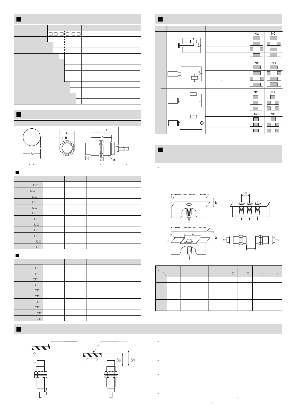
Operating Distance of Proximity Sensor :
When a proximity sensor is operating as a sensing object is approaching, a
distance between the sensing surface and the sensing object is the operating
distance of the proximity sensor.
Deciding Operating Distance
After measuring a maximum value of a perpendicular direction of a sensing
object, install it within 70 %.
Operating Distance of Each Proximity Sensor
When testing a sensing distance of a proximity sensor, a standard sensing
object was used so a sensing distance can be varied by its shape, form or
material. Please, consider these facts.
Operating Distance (Sa) Computing Equation:
Operating Distance (Sa) = Sensing Distance (Sn) 70 %
Ex) Operating Distance = 10 mm 0.7 =7 mm
When installing multiple (more than 2) sensors to be face to face which is
drawn the below or to be attached in parallel, it can be a cause of malfunction
by frequency interference and if there is metal around proximity sensor then it
is possible to occur malfunction such as reset defective and others so please
ensure the minimum distance is more than the value shown in the table.
2 Wire Type
Wiring Method Load Operation
DC Switching
N
P
N
P
N
P
Sensing Object
Operation Indicator
Presence
Nothing
Operation
Reset
H
L
ON
OFF
Presence
Nothing
Operation
Reset
H
L
ON
OFF
Load
[Brown (Red) Black (White)]
Output Voltage
[Black (White) Blue (Black)
Sensing Object
Operation Indicator
Load
[Black (White) Blue (Black)
Output Voltage
[Brown (Red) Black (White)]
ON
OFF
Sensing Object
Operation Indicator
Presence
Nothing
Operation
Reset
ON
OFF
Presence
Nothing
Operation
Reset
Load
Sensing Object
Operation Indicator
Load
Brown (Red)
Load
Blue (Black)
Blue (Black)
Black (White)
Brown (Red)
Load
Load
Brown (White)
Blue (Black)
Load
AC Switching
Black (White)
Brown (Red)
Blue (Black)
MODEL
Item HYP-
30R 10 HYP-
30R 15
a4.5 - 6 - 15 - 30 -
b- 6 - 12 -24-54
c82412 36 18 54 30 90
d0 8 0 11 014015
e1624 24 36 36 54 60 90
f91212 24 30 48 60 90
HYP-
8R1.5 HYP-
12R2 HYP-
12R4 HYP-
18R 5HYP-
18R 8
HYP-
8R2
M
8
8
12
12
18
18
18
18
30
30
30
30
Suffix Code
HYP-8R1.5
HYP-8R2
HYP-12R2
HYP-12R4
HYP-18R5
HYP-18R8
HYP-18RL5
HYP-18RL8
HYP-30R10
HYP-30R15
HYP-30RL10
HYP-30RL15
Mounting Hole Aspect Dimension
Gof the aspect dimension is categorized in unshielded type
F
-
-
-
-
47
37
80
70
57.8
47.8
79.8
69.8
E
-
-
42.8
35.3
40.5
30.5
73.5
63.5
50
40
72
62
G
-
4
-
7.5
-
10
-
10
-
10
-
10
D
33
29
32
24.5
29
19
62
52
38
28
60
50
C
15
15
21
21
29
29
29
29
41
41
41
41
B
13
13
17
17
23
23
23
23
35
35
35
35
A
9
9
13
13
19
19
19
19
31
31
31
31
Cable Length: 2m
H
3.4
3.4
4
4
4
4
4
4
5
5
5
5
AC Switching
M
12
12
18
18
18
18
30
30
30
30
Suffix Code
HYP-12R2
HYP-12R4
HYP-18R5
HYP-18R8
HYP-18RL5
HYP-18RL8
HYP-30R10
HYP-30R15
HYP-30RL10
HYP-30RL15
F
-
-
54
44
80
70
57.8
47.8
79.8
69.8
E
59.8
52.8
47.5
37.5
73.5
63.5
50
40
72
62
G
-
7.5
-
10
-
10
-
10
-
10
D
49
42
36
26
62
52
38
28
60
50
C
21
21
29
29
29
29
41
41
41
41
B
17
17
23
23
23
23
35
35
35
35
A
13
13
19
19
19
19
31
31
31
31
H
4
4
4
4
4
4
5
5
5
5
Metal
Metal
Sensing Object
Moving Direction
Moving
Direction
Sn: Sensing Distance
Sa: Operating Distance (70 % of Sn)
(a) (b)
Sensing Object
This manual suits for next models
30
Other Hanyoung Power Supply manuals

Popular Power Supply manuals by other brands


Hama
Hama Notebook Power Supply operating instructions

Allen-Bradley
Allen-Bradley ControlLogix 1756-PA50K Original instructions

Powerware
Powerware 9350 installation manual

EFOY
EFOY GO! manual

Thermal Arc
Thermal Arc PowerMaster 250 operating manual

ITW
ITW SIMCO ION D Series Installation and operating instructions