Sennheiser MZN 16 T User manual

11
a
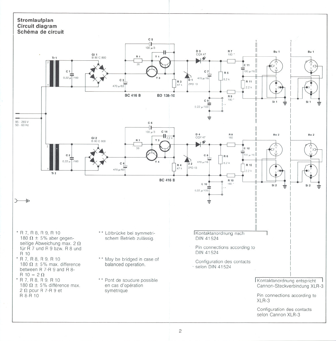
Stromlaufplan
Circuitdiagram
Schemada circuit
T.1
C 1
0,22 ~1/1O0
95-265V
50 - 60 Hz
C2
0,22 ~ 1/100
T.2
) 11'
*R 7, R 8, R 9, R 10
180 n :t 5% aber gegen-
seitige Abweichungmax. 2 n
für R 7 und R 9 bzw. R 8 und
R 10
*R 7, R 8, R 9, R 10
180 n :t 5% max.difference
between R 7-R 9 and R 8-
R 10 =2 n
*R 7, R 8, R 9, R 10
180 n :t 5% difference max.
2 n pour R 7-R 9 et
R 8-R 10
CS
~I-
100 ~/3
GI1
BBOC800
C3
4 70 ~/63
Be 416 B
C6
~I-
100 ~/3 C 14
GI2
B80C800
C4
470 ~/63
Be 416 B
* * Lötbrücke bei symmetri-
schem Betrieb zulässig.
* * Maybe bridged in case of
balanced operation.
* * Pont de soudure possible
en cas d'operation
symetrique
D4
COY 47
~
RB
180 Bu 2
R4
47 k
D2 470~/16
ZPD 13
11
11
11
11
11
11
11
11
11
IKontaktanordnungnach I
DIN41524
Configuration des contacts
.selon DIN41524
':' I
I
I
I
I
I
I
I
I
I
I
I
I
I
I
I
I
IKontaktanordnung entspricht I
Cannon-SteckverbindungXLR-3
Pin connections according to
XLR-3
Pin connections according to
DIN 41524
Configuration des contacts
selonCannonXLR-3
2
-- ---
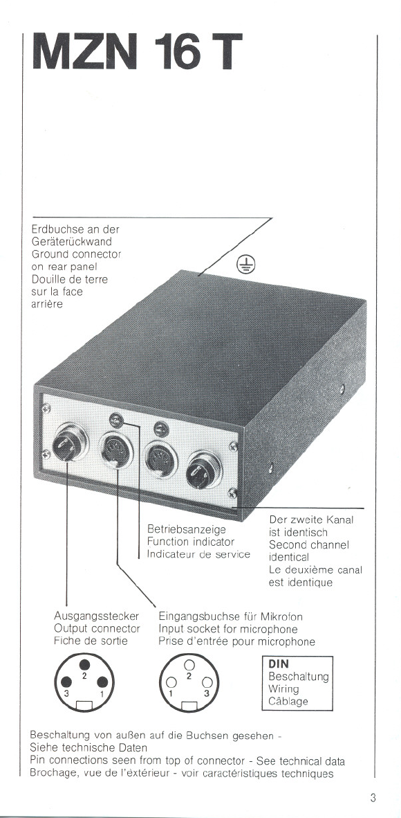
MZN 16T
Erdbuchse an der
Geraterückwand
Ground connector
on rear panel
Douille de terre
sur la face
arriere
Betriebsanzeige
Function indicator
Indicateur de service
Der zweite Kanal
ist identisch
Second channel
identical
Le deuxieme canal
est identique
Ausgangsstecker
Output connector
Fiche de sortie
Eingangsbuchse für Mikrofon
Input socket for microphone
Prise d'entree pour microphone
~
3 1 ~
1 3
DIN
Beschaltung
Wiring
Cäblage
Beschaltung von außen auf die Buchsen gesehen -
Siehe technische Daten
Pin connections seen from top of connector -See technical data
Brochage, vue de I'exterieur - voir caracteristiques techniques
3

MZN 16T-U
Eingangsbuchse für Mikrofon
Input socket for microphone
Prise d'entree pour microphone
0
W
Erdbuchse an der
Geräterückwand
Ground connector
on rear panel
Douille de terre
sur la face
arriere
Betriebsanzeige
Function indicator
Indicateur de service
Ausgangsstecker
Output connector
Fiche de sortie
n
~
Der zweite Kanal
ist identisch
Second channel
identical
Le deuxieme canal
est identique
U (XLR)
Beschaltung
Wiring
Cäblage
Beschaltung von außenauf die Buchsen gesehen -
Siehe technische Daten
Pin connections seen from top of connector -See technical data
Brochage, vue de I'exterieur -voir caracteristiquestechniques
4
BEDIENUNGSANLEITUNG
MZN 16T, MZN 16T- U
Netzgerät für Kondensatormikrofone mit 12 V-Tonader-
speisung nach DIN 45595
Das Netzgerät MZN 16 T und seine Variante MZN 16 T-U dienen zum
Betrieb von zwei tonadergespeisten Kondensatormikrofonen nach
DIN 45595.
Das äußerst robuste Ganzmetallgehäuse enthält zwei völlig getrenn-
te Stromversorgungskanäle mit je einem Netztransformator. Dadurch
ist eine völlige Entkopplung erreicht und es ist auch unsymmetri-
scher Betrieb eines oder beider Kanäle möglich.
Das Gerät arbeitet ohne Umschaltung an Wechselspannungsnetzen
zwischen 95 V und 265 V. Es enthält keine Sicherung, da die ver-
wendeten Transformatoren dauerkurzschlußfest sind. Das Netzgerät
ist schutzisoliert.
Die Betriebsbereitschaft wird durch je eine Leuchtdiode in jedem
Stromversorgungskanal angezeigt. Die Leuchtintensität wächst mit
dem Betriebsstrom des angeschlossenen Mikrofons.
Die beiden Stromversorgungskanäle sind dauerkurzschlußfest und
haben eine Strombegrenzung auf ca. 15 mA, so daß auch versehent-
lich angeschlossene dynamische Mikrofone nicht beschädigt werden
können Beide Kanäle sind galvanisch erdfrei. Die Modulationsadern
der angeschlossenen Leitungen dürfen ein Potential von max. 100 V =
gegen die Abschirmung aufweisen. So ist es beispielsweise auch
möglich, den Ausgang des Netzgerätes auf Leitungen zu schalten,
die für Phantomspeisung eingerichtet sind, ohne daß die Speise-
spannung abgeschaltet werden muß. Die Ausführung -U ist mit den
im Ausland gebräuchlichen XLR-3-Steckverbindungen ausgestattet.
5
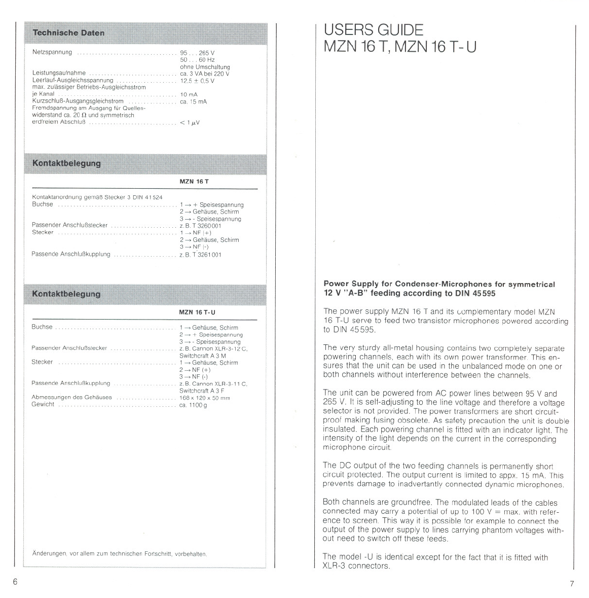
Netzspannung 95 265 V
50 60 Hz
ohne Umschaltung
ca.3 VAbei 220 V
12,5:t 0,5V
Leistungsautnahme . .
Leerlauf-Ausgleichsspannung ..
max. zulässiger Betnebs-Ausgleichsstrom
ie Kanal . .. . .. .
KurzschIuß-Ausgangsgleichstrom
Fremdspannung am Ausgang tür Quellen-
widerstand ca. 20 n und symmetrisch
erdfreiem Abschluß
10 mA
ca.15mA
<1/LV
Kontaktanordnung gemäß Stecker 3 DIN 41524
Buchse 1~-+-Speisespannung
2~Gehäuse,Schirm
3~- Speisespannung
z. B T 3260001
1~NF(-+-)
2~Gehäuse, Schirm
3~ NF(-)
z. B. T'3261 001
Passender Anschlußstecker
Stecker
Passende Anschlußkupplung
MZN 16 T-U
Buchse 1~Gehäuse,Schirm
2~-+-Speisespannung
3~- Speisespannung
z. B. Cannan XLR-3-12 C,
Switchcraft A 3 M
1~Gehäuse,Schirm
2~ NF(-+-)
3~ NF(-)
z. B. Cannan XLR-3-11 C,
Switchcraft A 3 F
168 x 120 x 50 mm
ca.1100g
Passender Anschlußstecker
Stecker
PassendeAnschlußkupplung
Abmessungen des Gehäuses
Gewicht
Änderungen, vor allem zum technischen Fortschntt, vorbehalten
6
USERSGUIDE
MZN 16 T, MZN 16 T- U
Power Supply tor Condenser-Microphones tor symmetrical
12 V "A-B" teeding according to DIN 45595
The power supply MZN 16 T and its complementary model MZN
16 T-U serve to feed two transistor microphones powered according
to OIN 45595.
The very sturdy all-metal housing contains two completely separate
powering channels, each with its own power transformer. This en-
sures that the unit can be used in the unbalanced mode on one or
both channels without interference between the channels.
The unit can be powered from AC power lines between 95 V and
265 V. It is self-adjusting to the line voltage and therefore a voltage
selector is not provided. The power transformers are short circuit-
proof making fusing obsolete. As safety precaution the unit is double
insulated. Each powering channel is fitted with an indicator light. The
intensity of the light depends on the current in the corresponding
microphone circuit.
The OC output of the two feeding channels is permanently short
circuit protected The output current is limited to appx. 15 mA. This
prevents damage to inadvertantly connected dynamic microphones.
Both channelsare groundfree. The modulated leads of the cables
connected may carry a potential of up to 100 V = max. with refer-
ence to screen. This way it is possible lor example to connect the
output 01the power supply to lines carrying phantom voltages with-
out need to switch off these leeds.
The model -U is identical except lor the lact that it is litted with
XLR-3 connectors.
7

"
Femaleeonneetor 1 ~housing, sereen
2~+ supply voltage
3~- supply voltage
e,g, Cannon XLR-3-12 C or
SWlteheraft A 3 M
1~ houslng, sereen
2 = audia 1+1
3 ~ audlo I-I
e,g, Cannon XLR-3-11 C or
Switchcraft A 3 F
168 x 120 x 50 mm
appx 1100 g
Corresponding eable eonneelor
Male canneetor
Correspandlng eable eonneelor
We reserve the light to alter speel!leatlons, in partleular wlth regard 10 teehnleal
improvemenls
8
MODE D'EMPLOI
MZN 16T, MZN 16T- U
Alimentation secteur pour microphones electrostatiques a
alimentation 12 V par conducteurs de modulation selon
DIN 45595
L'alimentation secteur MZN 16 T et sa variante MZN 16 T-U servent
a I'alimentation par conducteurs de modulation de deux micros electro-
statiques selon DIN 45595, Le bOItier tres resistant, entierement
metallique contient deux circuits d'alimentation, completement sepa-
res, et deux transformateurs-reseau. De cette maniere on arrive a
un decouplage complet et I'operation asymetrique d'un ou de deux
canaux est aussi possible.
L'appareil fonctionne, sans commutation, ades tensions alternatives
de 95 a 265 V. 11ne contient pas de fusibles, etant donne la resi-
stance aux courts-circuits permanente des transformateurs utilises
L'alimentation secteur est a isolement de protection.
Le pret pour le service est indique par la diode luminescente du
circuit d'alimentation correspondant. L'intensite lumineuse augmente
avec le courant d'alimentation du micro branche. Les deux circuits
d'alimentation sont resistants aux courts-circuits en -permanence.
La limitation du courant est d'environ 15 mA, ce qui evite la destruc-
tion de micros dynamiques, branches par megarde.
Les deux circuits sont sans mise a la terre galvanique. Les conduc-
teurs des cables raccordes peuvent avoir un potentiel maximum de
100 V tension continue par rapport au blindage. 11est ainsi possible,
de brancher la sortie de I'alimentation ades cables prevus pour une
alimentation fantöme, sans qu'il soit necessaire de mettre hors cir-
cuit I'alimentation.
Le modele -U est equipe de connecteurs XLR-3.
9

Consommation sur secteur ... .
Tension continue de sortie a vide .....
Courant contlnu de sortie max.par canal .. .
Courant continu de sortle en casde court-circuit .
Tension non-ponderee a lasortie pour une reslstance
interne d'environ 20 n et une terminalson symetrique,
sans mise a la masse
95. 265V
50..60Hz
sanscommulalion
env. 3 VA pour 220 V
12,5:t 0,5V
10mA
env. 15mA
< I!"V
Position des broches selon fiche 3 DIN 41524
Prise
Fiche de raccordappropriee
Fiche
1~alimentation(+)
2~boitier,blindage
3~alimentation(-)
p.ex T3260001
1 ~BF(+)
2 ~ bo1tter, blindage
3~BF(-)
p.ex. T 3261 001
Prise de raccordappropriee
Prise 1~boitier, blindage
2~alimentation(+)
3~alimentation(-)
p. ex. Cannon XLR-3-12 C
SWltchcrah A 3 M
1~boitier, blindage
2~ BF(+)
3~BF(-)
p. ex. Cannon XLR-3-11 C.
Switchcrah A 3 F
168 x 120 x 50 mm
env 1100g
Fiche de raccordappropriee
Fiche
Prise de raccordappropriee
Dimensions du boilier
Poids
Modi!ications, surtout dans I'inter,;t du progres technique, reservees.
10

Other Sennheiser Power Supply manuals


