Haojue HJ110-2 User manual

HJ110-2/2A
95500H51121H000
https://www.motomanuals.net/

https://www.motomanuals.net/
FOREWORD
This manual contains an introductory description
on HJ110-2/2A and procedures for their
inspection/maintenance and overhaul of their
main components. Other information considered
as generally known is not included.
Apprentice mechanics and do it yourself
mechanics will also find this an extremely useful
repair guide.
HAOJUE
JIANGMEN DACHANGJIANG GROUP CO.,LTD.
October, 2008
This manual provides you with more informa-
tion about your motorcycle and ensures users
best and quickest service.
This manual is for those adequately informed
and skilled in the maintenance of HAOJUE
motorcycle. If you are not well-informed and
skilled in this respect, you should not attempt
to effect maintenance and repair only by the
help of this manual.
This manual contain up-to-date information at
the time of its issue. There might be minor
discrepancies between your motorcycle and
this manual as a result of modifications made
after the publication of this manual.
Please contact your nearest authorized
HAOJUE motorcycle dealer.
*
*
*
https://www.motomanuals.net/
1
1-1
1-1
1-2
1-2
1-2
1-3
............................
...................................
.....................
...............................
..............................
..........................
GENERAL INFORMATION
CONTENTS
WARNING/CAUTION/NOTE
GENERALPRECAUTIONS
SERIALNUMBER LOCATIONS
FUELAND OILRECOMMENDATIONS
BREAK-IN PROCEDURE
SPECIFICATIONS
1
https://www.motomanuals.net/
Controlling torque
Near data indicates specified torque
OIL
A
S
M
No.4
1322
1342
BF
V
A
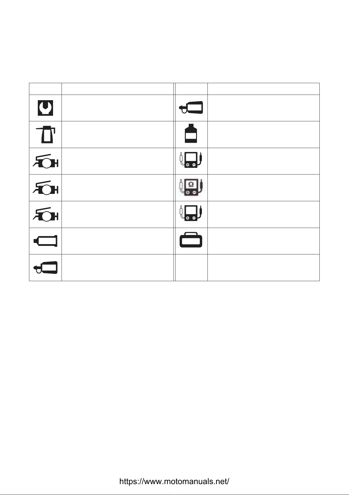
TOOL
Oil filling
Use engine oil unless otherwise stated
SUPER SILICONE GREASE
SYMBOLS
The following symbols illustrate necessary information of directions and servicing.
Symbol Item Symbol Item
SUPER GREASE “A”
MOLYPASTE
BOND No.4
THREAD LOCK BOND “1322”
THREAD LOCK BOND “1342”
Filling or using brake fluid
Measuring the current
Using special tool
Measure the voltage
Measure the resistance
https://www.motomanuals.net/

WARNING
GENERALINFORMATION
WARNING/CAUTION/NOTE
Please read this manual and follow its instructions carefully. To emphasize special information, the symbol and the
words WARNING,CAUTION and NOTE have special meanings. Pay special attention to the messages highlighted by
these signal words.
Personal safety of the rider is involved, and disregard of the information could result in injury.
For the protection of the motorcycle, the instructions and rule must be highly strictly adhered to.
NOTE:
Advice to facilitate the repair of the motorcycle is given under this heading.caIculate
Please note, however, that the contained in this manual cannot possibly cover all
potential hazards relating to the servicing, or lack of servicing of the motorcycle. In addition to the WARNING and
CAUTION stated, you must use good judgment and basic mechanical safety principles. If you are unsure about how to
perform a particular service operation, ask a more experienced mechanic for advice.
WARNINGS and CAUTIONS
GENERAL PRECAUTION
●
●
Proper service and repair procedures are important for the safety of the servicing mechanic, the safety and the
reliability of the motorcycle.
When 2 or more persons perform work in cooperation, pay attention to safety of each other.
When it is necessary to run the engine indoors, make sure that exhaust gas is forced outdoor.
When working with toxic or flammable materials, make sure that the area you work in is well-ventilated and that
you follow all of the material manufacturer's instructions.
Never use fuel as a cleaning solvent.
To avoid getting burned, do not touch the engine, engine oil and muffler until they have cooled.
After servicing the fuel, oil, muffler or brake system, check all hoses and fittings related to the system for leaks.
●
●
●
●
●
●If parts replacement is necessary, replace the parts with the HAOJUE GENUINE PARTs or their equivalent.
When removing parts that are to be reused, keep them arranged in an orderly manner so that they may be
reinstalled in the proper order and orientation.
Be sure to use special tools when instructed.
Make sure that all parts used in reassembly are clean. Lubricate them when specified.
lubricant, bond, or sealant.
When performing service to electrical parts, if the service procedures not required to use the battery power,
disconnect the positive pole.
When removing the battery, disconnect the negative wire first and then the positive wire.
When reconnecting the battery, connect the positive wire first and then the negative wire, and place the pole
cover on the positive pole.
ightening cylinder head and crankcase bolts and nuts, tighten the larger sizes first.
Always tighten the bolts and nuts diagonally from the inside working out.
Whenever you remove oil seals, gaskets, packing, O-rings, lock washers, cotter pins, circlips, and certain
other parts as specified, be sure to replace them with the new ones.Also, before installing these new parts, be
sure to remove any left over material from the mating surfaces.
Never reuse a circlip. When installing a new circlip, take care not to expend the end gap larger than required to
slip the circlip over the shaft.After installing a circlip, always ensure that it is completely seated in its groove and
securely fitted.
Do not use self-lock nuts a few times over.
Use a torque wrench to tighten fasteners to the specified torque, and wipe off grease or oil if a thread is
with them.
After reassembly, check parts for tightness and proper operation.
●
●
●
●
●
●
●
●
●
●
●
●
Use the specified
When t
smeared
NOTE:
●
●To protect environment, do not unlawfully dispose of used engine oil and other fluids, batteries and tires.
To protect Earth's natural resources, properly dispose of the used motorcycle and parts.
1-1
CAUTION
WARNING
CAUTION
https://www.motomanuals.net/
GENERALINFORMATION
1
2
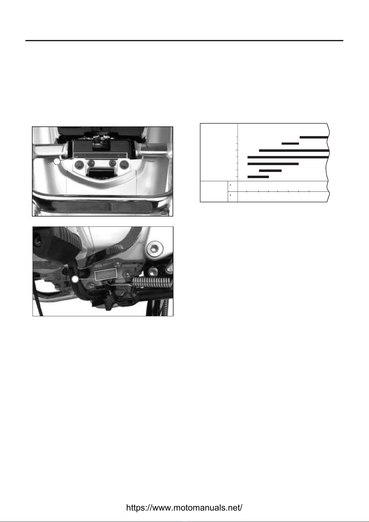
SERIAL NUMBER LOCATIONS
The V.I.N (Vehicle Identification Number) is
stamped on the chassis rear under the saddle.
The engine serial number is located on the
lower of the left crankcase.
①
②
These numbers are required especially for
registering the motorcycle and ordering the spare
parts.
ENGINE OIL
SAE
20W/50
10W/50
10W/30
20W
10W
40
30
C
F
-20
-4
-10
14
0
32
10
50
20
68
30
86
40
104
Temp.
BREAK-IN PROCEDURE
During the manufacture only the best ossible
are used and all machined parts are
finished to a very high standard
allow the moving part to “BREAK-IN”
subjecting the engine to maximum
stresses s the care and restraint
exercised during its early life The general rules
are as follows:
p
materials ,itisstill
necessary to
before . The future performance and reliability
of the engine depend on .
●
●
●
1-2
The break-in mileage is 500 km.
The throttle must not be opened to the full during
the new motorcycle's break-in period. Throttle
opening should be limited to 3/4 of its maximum,
while violent acceleration should be avoided.
Do not maintain constant engine speed for an
extended time period during any portion of the
break-in. Try to vary the throttle position.
≦
FUEL AND OIL
RECOMMENDATIONS
FUEL
Use fuel with an octane number of 90-97
(Research method), preferably unleaded.
NOTE:
Unleaded fuel will extend spark plug life.
Be sure that the motorcycle engine oil you use
comes underAPI classification of SF or SG and its
viscosity rating is SAE 10W-40. If SAE 10W-40
engine oil is not available, select the oil viscosity
according to the following chart:
https://www.motomanuals.net/

...........................................
..........................................
...........................................
..........................................
............................................
.......................................
1909 mm HJ110-2) 1906 mm(HJ110-2A)
677 mm(HJ110-2) 676 mm(HJ110-2A)
1088 mm(HJ110-2) 1085 mm(HJ110-2A)
1218 mm(HJ110-2) 1202 mm(HJ110-2A)
120 mm
104 kg(HJ110-2) 106 kg(HJ110-2A)
(
Four-stroke, air-cooled, OHC
1
52.4 mm
49.5 mm
107 ml
9.1:1
VM type PZ26S
Polyurethane foam element
Electric starter with kick starter
Pressure splash
Wet automatic centrifugal type
Reciprocalshift(driving), cyclic shift(parking)
4-speed gear transmission
4.059
2.571
2.833
1.705
1.238
0.958
428, 100 links
..................................................
.....................................
..................................................
.................................................
....................................
......................................
.............................................
........................................
......................................
.............................................
.................................................
.......................................
......................................
.........................................
..........................................
........................................
.........................................
.........................................
.........................................
............................................
SPECIFICATIONS
DIMENSIONS AND CURB WEIGHT
Overall length
Overall width
Overall height
Wheelbase
Ground clearance
Curb weight
ENGINE
Type
Number of cylinders
Bore
Stroke
Piston displacement
Compression ratio
Carburetor
Air cleaner
Starting system
Lubrication system
TRANSMISSION
Clutch
Transmission
Gearshift pattern
Primary reduction
Final reduction
Gear ratios, low
2nd
3rd
4th
Drive chain
GENERALINFORMATION
1-3
https://www.motomanuals.net/

DC-CDI
15° B.T.D.C. below 1500r/min and
30° B.T.D.C. above 5000r/min
TORCHA7RC or NHSP LDA7RTC
12V 5Ah
15A
12V, 35W/35W
12V, 5W/21W
12V, 21W (front) 12V,21W(rear) (HJ110-2)
12V, 21W (front 12V,16W(rear) (HJ110-2A)
12V, 5W
12V, 2W×5
12V, 2W
12V, 2W
12V, 2W×2
)
...........................................
.........................................
.............................................
................................................
..................................................
................................
........................................
..............................................
.........................................
...........................................
...................................
.............................
................................
..................................................
................................................
.......................................
............................................
..........................................
..........................................
.......................................
.......................................
.........................................
............................................
ELECTRICAL
Ignition type
Ignition timing
Spark plug
Battery
Fuse
Headlight
Tail/Brake light
Turn signal light
Position light
Gear position indicator light
Dashboard panel light
High beam indicator light
Turn signal indicator light
CHASSIS
Front suspension
Rear suspension
Steering angle
Caster
Trail
Turning diameter
Front brake
Rear brake
Front tire size
Rear tire size
Telescopic, coil spring, oil dampened
Swing arm, oil dampened
coil spring 5-way adjustable
42°
27°
93 mm
3.7 m
Internal expanding
2.50-17-4PR
2.75-17-4PR
coil spring,
Internal expanding
CAPACITIES
Fuel tank including reserve
Engine oil
Front absorber oil
4.7 L
900 ml
57 ml
GENERALINFORMATION
1-4
..............................
.............................................
.....................................
*These specifications are subject to change without notice.
https://www.motomanuals.net/

2
PERIODIC MAINTENANCE
2
CONTENTS
PERIODIC MAINTENANCE
MAINTENANCE PROCEDURES
BATTERY
VALVE CLEARANCE
SPARK PLUG
THROTTLE CABLE PLAY
FUEL HOSE AND SECONDARY AIR HOSE
FUEL FILTER
DRIVE CHAIN
BRAKES
TIRES
STEERING
FRONT/REAR
LIGHTS AND SIGNAL LIGHTS
CHASSIS AND ENGINE MOUNTING BOLTS AND NUTS
COMPRESSION PRESS
AIR CLEANER
ENGINE OIL
OIL STRAINER
CLUTCH
CARBURETOR
ABSORBER
MUFFLER MOUNTING NUTS & BOLTS
CYLINDER HEAD & CYLINDER NUTS &BOLTS
...........................
......................
...........................................
...................
..................................
........................................
......
.........................................
.......................................
.......................................
............................................
........................................
...............................
..........................................
..............................................
............................................
.......................................
...............................
2-3
2-4
2-5
2-5
2-6
2-7
2-8
2-9
2-9
2-9
2-10
2-10
2-10
2-11
2-14
2-15
2-16
2-16
2-17
2-17
2-18
.......................................
2-1
2-3
..........................
...........................
................
............
https://www.motomanuals.net/
PERIODIC MAINTENANCE
The chart below lists recommended intervals for all the required periodic service work necessary to keep
the motorcycle operating at performance and economy. Mileage are expressed in terms of kilometer and
times for your convenience.
NOTE:
More frequent servicing should be considered if the motorcycle is operated under the rough conditions.
PERIODIC MAINTENANCE CHART
INTERVAL
ITEM km
month
Clutch
Carburetor (Idle speed)
Oil strainer
Engine oil
Spark plug
Valve clearance
Air cleaner
Battery
PERIODIC MAINTENANCE
2-1
_
_
_
_
_
6,000
12
_
6
1,000
3
2-3
2-5
2-4
2-6
2-7
2-8
2-9
2-9
2-9
PAGE
Inspect
Inspect
Inspect
Inspect
Inspect
Tighten
Clean
3,000
Inspect
Inspect
Inspect
Inspect
Inspect
Tighten
Clean
The first change at Initial 500 km, the second
change at 1,000km total mileage, while
further change Every 3,000 km.
Clean Every 12,000 km
Replace Every 12,000 km
Throttle cable play _
2-10
Inspect Inspect
Front and rear absorber
Chassis and engine mounting bolts
and nuts
Steering
Tires
Brakes
Drive chain
Fuel filter
Fuel hose and secondary air hose
Lights and signal lights
Inspect
Inspect
Inspect
Inspect
Inspect
Inspect
Inspect
_
Inspect, clean & lubricate Every 1,000 km
Replace Every 4 years
Inspect
Inspect
Inspect
Inspect
Inspect
Inspect
Inspect
Inspect
_
_
_
_
_
_
_
2-10
2-10
2-11
2-14
2-15
2-16
2-16
2-17
2-17
NOTE:
The inspection items above may require, if necessary, further cleaning, tighten, adjustment or replacement
"- stands for not required."
Replace
Muffler mounting nuts &bolts _2-5
Tighten Tighten
Cylinder head&cylinder nuts &bolts
https://www.motomanuals.net/
_
_
_
_
_
_
12
LUBRICATION CHART
The following is a basic lubrication requirement for a motorcycle operated in an economical manner and
based on the mileage displayed by the odometer.
INTERVAL
ITEM km
month
Initial and Every 6,000 km Every 12,000 km
6
Engine oil
Grease
Engine oil Every 1,000 km
Grease or engine oil
Grease Every 2 years or 24,000 km
Grease
Grease
Grease
Throttle cable
Throttle grip
Odometer cable
Speedometer gear box
Drive chain
Brake pedal axle
Brake cam
Steering bearing
Rear rocker arm bearing bush
PERIODIC MAINTENANCE
2-2
NOTE:
“-"stands for not required
Do not apply too much lubrication grease on the brake cam to prevent the brake from slipping.
When driving on wet roads or under rainy conditions, lubricate the parts with engine oil or grease to avoid
rust. Be sure to remove oily contamination or rust.
WARNING
CAUTION
https://www.motomanuals.net/

+
-
MAINTENANCE PROCEDURES
BATTERY
Inspect at Initial 1,000 km and Every 3,000 km
Unlock and open the saddle; remove the wires
on both the positive and negative poles,
Remove the battery.
●
NOTE:
When remove the battery, remove the negative
wire first.
+_
_
Inspect the electrolyte level, which should be
kept within “UPPER LEVEL” (the upper limit)
and “LOWER LEVEL” (the lower limit). If the
level is below the , pour the
distilled water up to the .
“LOWER LEVEL”
“UPPER LEVEL”
●
NOTE:
Only the distilled water should be poured.
UPPER
LOWER
Once the battery is put into use, no more diluted
sulfuric acid should be poured.
Do not bend, clog the exhaust pipe of the
battery or alter its path. Make sure that one end
of the pipe is securely connected with the
battery while the another end is through.
When connecting to the battery, be sure to
connect the positive and negative poles
correctly. The red wire is for the positive pole
while the black wire is for the negative pole.
Wrongly connecting to the battery poles may
result in damage to the electrical circuit and the
battery itself.
Please refer to page 6-12 for information about the
battery charging time and current.
PERIODIC MAINTENANCE
2-3
WARNING
CAUTION
https://www.motomanuals.net/
1
2
43
front
cover
screw
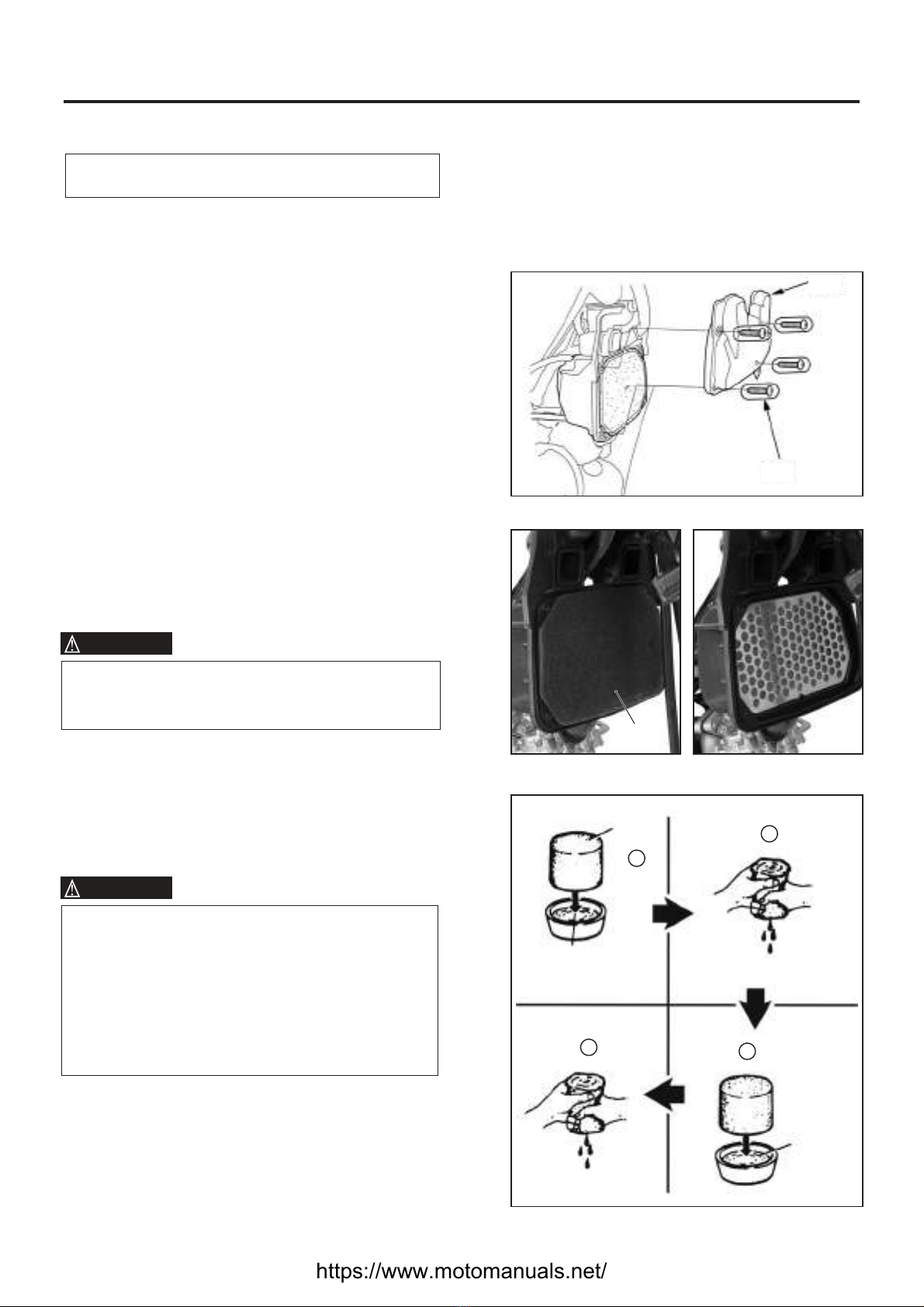
AIR CLEANER
Clean at Initial 1,000 km and Every 3,000km.
If the air cleaner is clogged with dust, intake
resistance will be increased with a resultant
decrease in power output and an increase in fuel
consumption.
Remove the front basket (for HJ110-2) and the
front panel,
Remove s
Loosen the front cover screws of the air cleaner
element, remove the front cover, the element
and the element support.
.the front left / right side cover
Pour non-flammable detergent into a wash pan
of appropriate size, dip the element into the
detergent solution and clean it.
Squeeze the liquid out of the element by
pressing it with both hands. Never twist the
element to avoid breaking it.
Dip the element into the engine oil again,
squeeze out excessive oil to keep the element
slightly wet.
●
●
●
●
●
●
Look carefully for fractures on the element
before and during cleaning. In case fractures
are found, replace the element immediately.
Assemble the element in the reversed order of
disassembly. Make sure the element is
correctly installed at specified position and
properly sealed.
●
When driving in dusty environments, please
carry out filter element inspection, clean and
replacement more frequently. If any
defect such as clog, damage or dust infiltra-
tion occurs, replace it immediately. Do not
wait until the next scheduled maintenance.
Start the engine without installing the
filter element will accelerate engine wear-off.
Engine oil
Non-flammable
detergent
Element
Element
PERIODIC MAINTENANCE
2-4
WARNING
WARNING
https://www.motomanuals.net/

CYLINDER HEAD & CYLINDER
NUTS & BOLTS
Tighten at Initial 1,000 km and Every 3,000 km
CYLINDER HEAD LEFT NUT
Tighten the right nut of the cylinder head to the
s.pecified torque
●
Specified torque: 8-12 N m•
Specified torque: 15-18 N m•
CYLINDER HEAD NUTS
●Tighten the nuts of cylinder head
.to the
specified torque
CYLINDER HEAD SIDE BOLT
Specified torque: 15-18 N m•
Specified torque: 8-12 N m•
CYLINDER MOUNTING BOLT
Tighten the cylinder connecting bolt
.to the
specified torque
●
●Tighten the cylinder mounting bolt
.to the
specified torque
PERIODIC MAINTENANCE
2-5
Cylinder mounting bolt
Cylinder head side bolt
MUFFLER MOUNTING NUTS & BOLTS
Tighten the muffler mounting nuts and bolts.
●
Inspect at Initial 1,000 km and Every 3,000 km
https://www.motomanuals.net/

1
3
2
VALVE CLEARANCE
Inspect at Initial 1,000 km and Every 3,000 km
Remove spark plug, valve inspecting caps
and valve timing inspecting plug . ①,
③
Remove the generator cover cap and rotate
the generator rotor with a 14-mm socket
wrench to set the piston at T.D.C of the
compression stroke.
(Rotate the generator rotor until the “T”line on
the rotor is aligned with the center of hole on
the left crankcase cover.)
②
The crankshaft must be rotated counter-
clockwise. If the crankshaft is already rotated
clockwise due to negligence, it must then be
rotated counterclockwise by two or more turns.
The adjusted valve can only be ensured to be
correct when the “T” mark on the rotor is
aligned with the mark line on the crankcase.
Since when crankshaft rotates clockwise, the
pressure-reducing cam takes action to result in
incorrect valve clearance.
Insert the thickness gauge between the tappet
adjusting screw and valve stem to measure the
clearance of the intake/exhaust valve.
0.03-0.07 mm
09900-20803 Thickness gauge:
TOOL
●
●
●
Valve clearance
Thickness guage
NOTE:
The valve clearance must be checked and
adjusted under cooled engine states.
PERIODIC MAINTENANCE
2-6
CAUTION
https://www.motomanuals.net/
ADJUSTMENT
Loosen the lock nut, turn the tappet adjusting
screw until the gauge feels a slight resistance.
Fix the tappet adjusting screw and tighten the
lock nut to the specified torque.
●
●
09917-14910: Tappet adjusting driver
TOOL
Check the valve clearance again.
Check if the O-ring of the valve inspecting caps
is damaged, replace it if necessary.
Apply engine oil on the O-ring, and mount it
onto the valve inspection caps.
Apply engine oil on the thread of the valve
inspecting caps, and tighten to the specified
torque.
●
●
●
●
Specified torque: 10-14 N m•
Check if the O-rings f
and is damaged,
replace if necessary.
Apply engine oil on the thread parts of both
, and install them.
o valve timing inspection
plug the generator cover cap
valve timing inspection plug and the generator
cover cap
●
●
SPARK PLUG
Inspect at I Every 3,000 km.nitial 1,000 km and Replace Every 12,000 km.
TORCH NHSP LDA6RC or A6RTC
TYPE
KIND
O ring
PERIODIC MAINTENANCE
2-7
Remove the spark plug with a socket wrench.
●
TORCH NHSP LDA7RC or A7RTC
TORCH NHSP LDA8RC or A8RTC
STANDARD
COLDTYPE
HOTTYPE
Pay attention to the color of the ceramic and the electrode of the spark plug. The status of the spark plug
can be determined by observing its color. If the standard spark plug looks wet and black, use a hot plug
instead. If the spark plug looks white, it means that the spark plug has overheated and should be replaced
with a cold one.
ELECTRODE’S CONDITION
Check for the worn or burnt condition of the electrodes. If it is extremely worn or burnt, replace the spark
plug.And also replace the spark plug if it has a broken insulator, damaged thread, etc.
https://www.motomanuals.net/
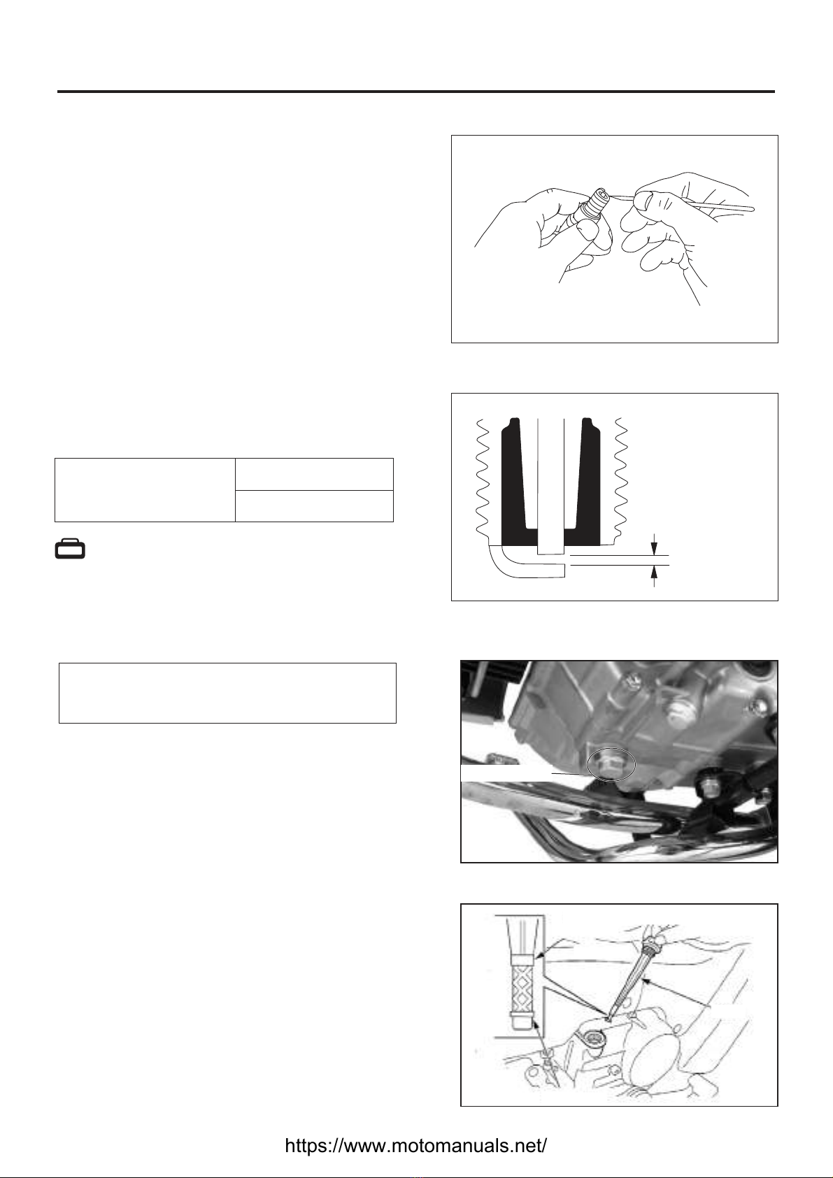
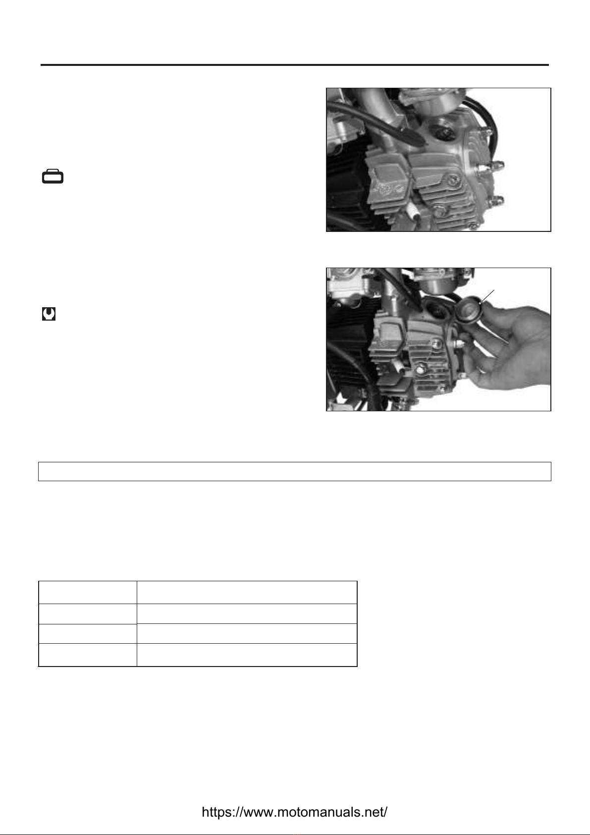
ENGINE OIL
The first change at Initial 500 km, the second
change at 1,000km total mileage, while further
change Every 3,000 km.
Engine oil replacement should be made when the
engine is warm as follows:
Support the motorcycle by the main stand.
Remove the draining bolt on the engine bottom
to drain out the used engine oil after unscrew-
ing the filling hole cover.
Check whether the sealing washer of the
draining bolt is properly mounted; screw the
draining bolt properly to avoid over-tightening.
Fill 800 ml (the first filling of a new motorcycle is
900 ml) engine oil into the filling hole; screw the
filling hole cover properly to avoid over-
tightening.
Start the engine, keep it at idle speed for several
minutes.
Shut down the engine, 1 minute later, check the
oil lever. The oil level should be near the upper
limit mark.
●
●
Draining bolt
PERIODIC MAINTENANCE
CARBON DEPOSIT
Check for the carbon deposit on the plug.
If the carbon is deposited, remove it with a spark
plug cleaner machine or .a needle carefully
SPARK PLUG GAP
Measure the spark plug gap with a thickness gauge
if it is correct. If not, adjust it to the following gap.
Spark plug gap Standard
0.6~0.8 mm
09900-20803: Thickness gauge
TOOL
2-8
●
●
Lower limit
Upper limit
Cover
●
●
0.6-0.8 mm
https://www.motomanuals.net/

OIL STRAINER
Clean Every 12,000 km
The right crankcase cover has to be removed to
check the engine oil strainer. Replace with a new
one if necessary.
PERIODIC MAINTENANCE
2-9
CAUTION
Since the right crankcase cover has to be remov-
ed to check the engine oil strainer, the decision
to replace the strainer should be made by
qualified
Check careful for any oil leak at the
draini g boltn
mechanic.
ly age
.
(HJ110-2) (HJ110-2A)
Inspect at Initial 1,000 km and Every 3,000 km
CLUTCH
Support the motorcycle with the main stand.
Remove the brand plate cover (HJ110-2A).
Loosen the lock nut of clutch adjusting screw
rotate the adjusting screw clockwise by 1 turn
(do not overturn), rotate the adjusting screw
counterclockwise slowly until feeling a slight
resistance.
Rotate the adjusting screw clockwise by 1/18
turn and tighten the lock nut to the specified
torque.
●
●
●
●
NOTE:
When tightening the lock nut, fix the adjusting
screw.
After adjusting, check the operation of the clutch.
Specified torque: 15-18 N m•
(HJ110-2) (HJ110-2A)
Adjusting screw
Lock nut
2
Inspect at Initial 1,000 km and Every 3000 km,
CARBURETOR (IDLE SPEED)
Start the engine, keep it at idle speed till fully
pre-heated.
counter-
clockwise ②
Once the engine has pre-heated, release the
throttle; turn the pilot screw and the air
adjusting screw clockwise or
to keep the idle speed within
1,400~1,600 RPM(refer to page 4-6).
①
●
●
1
NOTE:
The adjustment of the engine idle speed should
be done when the engine has fully pre-heated.
https://www.motomanuals.net/

Inspect at Initial 1,000 km and Every 3,000 km.
6,000 kmReplace Every .
FUEL FILTER
If the fuel filter is dirty with sediment, fuel will not
flow smoothly and may
result.
Clean the filter cup with non-flammable
detergent.
decrease in power output
PERIODIC MAINTENANCE
2-10
THROTTLE CABLE PLAY
Loosen the lock nut .
Turn the adjuster to adjust the cable play to
keep it between 0.5-1.0 mm.
Tighten the lock nut securely after the play
adjustment is completed.
●
●
●
0.5~1.0 mm
Throttle cable play
WARNING
0.5 1.0 mm~
Lock nut
Adjuster
Inspect at Initial 1,000 km and Every 3,000 km
Replace Every four years.
FUEL HOSE AND SECONDARY AIR HOSE
Check for damage, fracture or fuel leakage on the
fuel hose and secondary air hose as well as their
connections. If problem was found, replace the
fuel hose or the secondary air hose immediately.
Fuel hose
Secondary
air hose
Inspect at Initial 1,000 km and Every 3,000 km.
After the adjustment of throttle cable play was
completed, make sure that and
the adjustment has not raised the engine idle
speed.
the throttle grip
position should be able to return freely,
In the meantime, make sure that the engine
idle speed was not caused to change while
turning the handlebar to the left and right.
https://www.motomanuals.net/
This manual suits for next models
1
Table of contents
Other Haojue Motorcycle manuals

Haojue
Haojue EG150 User manual

Haojue
Haojue EG125 User manual

Haojue
Haojue HJ125-7 User manual

Haojue
Haojue EH150 User manual

Haojue
Haojue TZ150S 2015 User manual

Haojue
Haojue NK150 2020 User manual

Haojue
Haojue HJ125-16 User manual

Haojue
Haojue TZ125 User manual

Haojue
Haojue XPRESS User manual

Haojue
Haojue HJ125-8 User manual


