Harbor Freight Tools 91286 User manual

PHOTO SNIPER CAMERA
MODEL 91286
ASSEMBLY AND OPERATING INSTRUCTIONS
3491 Mission Oaks Blvd., Camarillo, CA 93011
Visit our Web site at http//www.harborfreight.com
Copyright 2004 by Harbor Freight Tools. All rights reserved. No portion of this
manual or any artwork contained herein may be reproduced in any shape or form
without the express written consent of Harbor Freight Tools.
For technical questions, please call 1-800-444-3353.
®
®
©

PRODUCT SPECIFICATIONS
SAVE THIS MANUAL
You will need this manual for the safety warnings and precautions, assembly, operating,
inspection, maintenance and cleaning procedures, parts lists and assembly diagrams.
Keep your invoice with this manual. Write the invoice number on the inside of the front
cover. Keep this manual and invoice in a safe and dry place for future reference.
UNPACKING
When unpacking, check to make sure all the parts listed in the Parts List on page 17 are
included. If any parts are missing or broken, please call Harbor Freight Tools at the num-
ber shown on the cover of this manual as soon as possible.
SKU 91286 PAGE 2
GENERAL SAFETY WARNINGS AND PRECAUTIONS
1. Use this product only in clean and dry areas. Cluttered, damp, or wet areas
invite injuries.
2. Do not allow children to handle this product. This product contains small
parts that could be swallowed or choked on.
Item Description
Camera Make/Model Zenit 122S.
Frame Size 24 x 36mm.
Number of Frames 36.
Film Type 35mm / Perforated.
Interchangeable
Lens Types MC Tair-3S 300mm F/4.5 Telephoto.
MC Helios 44M-6 58mm F/2.
(Both with 42mm Mounting Thread).
Shutter Speed 1/30, 1/60, 1/125, 1/250, 1/500.
Minimum Flash Synchronization 1/30 Second.
Focusing Manual with Split Image.
Light Filters Qty. 5.
Light Yellow / Yellow / Green / Orange / Clear.
Battery Type
(Not Included) Qty. 2.
EXP 76, S76, SR44, or Equivalent.
Tripod Stock Mount 3/8” x 16.
Accessories Carrying Case, Shoulder Strap, Screwdrivers (Qty. 2
)
Net Weight 11.25 Pounds.
®

SKU 91286 PAGE 3
3. Check for damaged parts. Before using this product, carefully check that it will
operate properly and perform its intended function. Check for damaged parts
and any other conditions that may affect the operation of this product. Replace
or repair damaged or worn parts immediately.
4. Replacement parts and accessories: When servicing, use only identical re-
placement parts. Only use accessories intended for use with this product.
Approved accessories are available from Harbor Freight Tools. (Some parts are
listed and shown for illustration purposes only, and are not available individually
as replacement parts.)
5. Maintain this product with care. Keep this product clean and dry during stor-
age for better product performance. Service and maintenance should be per-
formed regularly by a qualified technician.
6. Use the right product for the job. Do not attempt to force small products to do
the work of larger commercial products. There are certain applications for which
this product was designed. It will do the job better at the rate for which it was
intended. Do not modify this product, and do not use this product for a purpose
for which it was not intended.
7. WARNING! The warnings, precautions, and instructions discussed in this manual
cannot cover all possible conditions and situations that may occur. The operator
must understand that common sense and caution are factors, which cannot be
built into this product, but must be supplied by the operator.
SPECIFIC PRODUCT WARNINGS AND PRECAUTIONS
1. The Photo Sniper Camera and its accessories are delicate, precise, photo-
graphic equipment and should be handled carefully and kept clean and dry
to avoid damage. When not in use, keep the Camera and its accessories in
their Carrying Case (79). Dust and moisture can damage the equipment.
2. To avoid sweating on the optical parts, do not remove the Camera or its
accessories from its Carrying Case (79) immediately when it is brought
indoors from the cold. Allow sufficient time for the Camera and its accessories
to warm up to room temperature in the closed Carrying Case.
3. Do not touch the optical parts of the Camera or its accessories with your
fingers; doing so may damage their multilayer coating. If necessary,
clean the Lenses (31, 78) with professional lens cleaning products. Do not clean
with moist cleaning agents.
4. When not in use, always cover the Lenses (31, 78) with their Lens Caps.

SKU 91286 PAGE 4
5. When not in use, the Camera’s Shutter (48) should be released. Do not keep
the Shutter cocked for a long period of time. Do not attempt to rotate the Shutter
Speed Dial (46) in a short interval between the positions “500” and “B”. Do not
rotate the Shutter Speed Dial when setting the Film Rewind Knob (49) in the “T”
position and when the Self-Timer (35) is running.
6. To prevent dust and dirt from getting on the surfaces of the optical parts
and into the Camera, remove the Lens (31) only when necessary.
7. Always load and unload the Camera’s Film (not included) in shade or in-
doors. Avoid direct sunlight.
8. The Camera’s Exposure Meter will not operate without Batteries (not in-
cluded). When not in use over a long period, the Film Rewind Knob (49) should
not be in its “V” position to avoid premature discharging of the Batteries. During
long intervals between taking pictures (weeks, months), removing the Batteries
from the Camera is recommended.
9. Because the Photo Sniper Camera is a complex device, any repair and
adjustments should be performed
only
by a highly qualified specialist.
CAMERA AND ACCESSORY FEATURES
ZENIT -122S CAMERA
(1)
SHOULDER STOCK
(10)
SHOULDER STOCK CLAMP
(9)
CLAMPING SCREW
(8)
SUPPORTING RING
(7)
TRIGGER
(6)
TRIPOD SCREW
(5)
LENS HOOD
(4)
MC TAIR-3S 300MM LENS
(3)
CONNECTING WIRE
(2)
FIGURE A
®
PISTOL
GRIP
(41)
43: CARRYING STRAP NOT SHOWN
PARTS LIST A ®

SKU 91286 PAGE 5
APERTURE
SETTING
KNOB
(11)
APERTURE
SETTING
RING
(12)
DIAPHRAGM
SCALE
(13)
SHOULDER
STOCK
CHAMBER
(14)
DIAPHRAGM
ADVANCE
ADJUSTMENT
SCREW
(16)
.
.
PUSH SCREW
RELEASE
(17)
STRAP
EYELET
(15)
DIAPHRAGM
RELEASE
LEVER
(18)
GUIDE
PIN
BRACKET
(19)
FOCUSING
DRUM
(20)
DISTANCE
SCALE
(21)
DISTANCE
SETTING
INDEX
(22)
STRAP
EYELET
(15)
FIGURE B
SHUTTER COCKING
& FILM ADVANCE
LEVER
(28)
FRAME
COUNTER
(27)
SHUTTER
BUTTON
(29)
SHUTTER
SPEED
DIAL
(30)
FILM
SPEED
DIAL
(26)
REWIND
CRANK
(25)
SELF-TIMER
DIAL
(23)
SELF-TIMER
RELEASE BUTTON
(24)
MC HELIOS 44M-6
58 MM LENS
(31)
FOCUSING RING (32)
APERTURE RING (33)
FIGURE C
FILM
REWIND
KNOB
(40)
PARTS LIST B
SHUTTER
RELEASE
BUTTON
(42)
PARTS LIST C
39: BATTERY CAP NOT SHOWN.

SKU 91286 PAGE 6
LIGHT FILTER FEATURES
1. The
five
accessory Light Filters (34, 35, 36, 37, 38) are used with the MC-Tair-3S
300 MM Lens (3). (See Figures A and D.)
2. CAUTION: To avoid stripping the threads of the Filters and/or Lens, always
use care when screwing the Filters into the Lens. (See Figure D.)
3. The Light Filters (34, 35, 36, 37, 38) have the following features: (See Figure D.)
A light-yellowFilter (34) for improved color rendition of blue, green, and
yellow objects in portraiture under natural illumination, in nature shots
under a clouded blue sky, and in any landscape photography at short
exposure in the evening. (See Figure D.)
A yellow Filter (35) for use in landscape photography at short exposure in the
evening. (See Figure D.)
A green Filter (36) for correct color rendition (particularly red and green
colors) on panchromatic films. (See Figure D.)
An orange Filter (37) for use in eliminating the effect of atmospheric haze and
provides images with increased contrast on B & W film. (See Figure D.)
A UV-haze Filter (38) is a clear Filter designed to eliminate the influence of
ultraviolet rays in both B & W and color photography. (See Figure D.)
LIGHT-YELLOW
(34)
GREEN
(36)
YELLOW
(35)
ORANGE
(37)
UV-HAZE
(38)
FIGURE D
PARTS LIST D

SKU 91286 PAGE 7
ASSEMBLY AND OPERATING INSTRUCTIONS
1. The Camera uses two Batteries. (See
“Product Specifications”
Chart, p. 2.)
To install the Batteries, use the access-
ory Screwdriver to turn the Battery Cap
(39) (in the white circle) counterclock-
wise. Remove the Battery Cap. Insert
the Batteries in the Battery Chamber
with their positive (+) ends facing out-
ward. Then, replace the Battery Cap,
and turn it clockwise to lock it in place.
(See Figure E.) FIGURE E
FIGURE F
FIGURE G
2. Before taking pictures, the Frame
Counter (27) must be set to “S”. To do
so, depress the Film Rewind Knob (40)
(in the white circle). Then, set the Frame
Counter to “S”. (See Figure F.)
3. To load the Film (not included), pull up
the Rewind Crank (25) to open
the Rear Cover. (See Figure G.)
REWIND CRANK (25)
BATTERY CAP
(39)
FILM
REWIND
KNOB
(40)

SKU 91286 PAGE 8
FIGURE J
4. Insert the Film Cartridge in the left
compartment. Slide the Film tip in
the socket of the Take-Up Spool in
the right compartment and rotate the
Spool a little with a finger to roll the
Film around it. Make sure the Film
perforations are properly engaged
with the Sprockets in the Take-Up
Spool. Then, close the Rear Cover
of the Camera. (See Figure H.)
FIGURE H
FIGURE I
5. Make “blind” exposures until the Frame
Counter (27) is set to the position of “1”
(between “0” and “2). (See Figure I.)
6. The film speed is set with the Film
Speed Dial (26) around the Rewind
Crank (25). IMPORTANT:Improper
setting of the film speed will result in
wrong exposure and the frames on the
film may be too light or too dark.
(See Figure J and
Figure K, next page.)
FRAME COUNTER
(27)
FILM SPEED
DIAL
(26)
REWIND
CRANK
(25)
TAKE-UP SPOOL

SKU 91286 PAGE 9
FIGURE K
Film Speed Scale ……...25………….50………….100…………….200…………….400…………..
GOST/ISO 16 20 25 32 40 50 64 80 100 125 160 200 250 320 400 500 640
DIN 13 14 15 16 17 18 19 20 21 22 23 24 25 26 27 28 29
REFERENCE TABLE OF FILM SPEEDS
The shutter speed is selected with the
Shutter Speed Dial (30). The numbers
on the Shutter Speed Dial indicate
shutter speeds in corresponding frac-
tions of a second. “B” indicates a hand-
controlled shutter speed. Shutter
speeds can be set with both the shutter
cocked and released. When taking pictures at “B” the shutter remains open for as
long as the Shutter Button (29) is depressed. To obtain a long exposure, turn the
depressed Shutter Button counterclockwise as far as it will go (to its “T” position).
When the exposure is over, return the Shutter Button to its normal (middle)
position and release it. This will result in closing the shutter. (See Figure L.)
FIGURE L
FIGURE M
7. By adjusting the shutter speed you can
control the movement of the subject
being photographed. A fast shutter
speed will freeze the subject, and a
slow shutter speed will make it look
blurred as the subject moves.
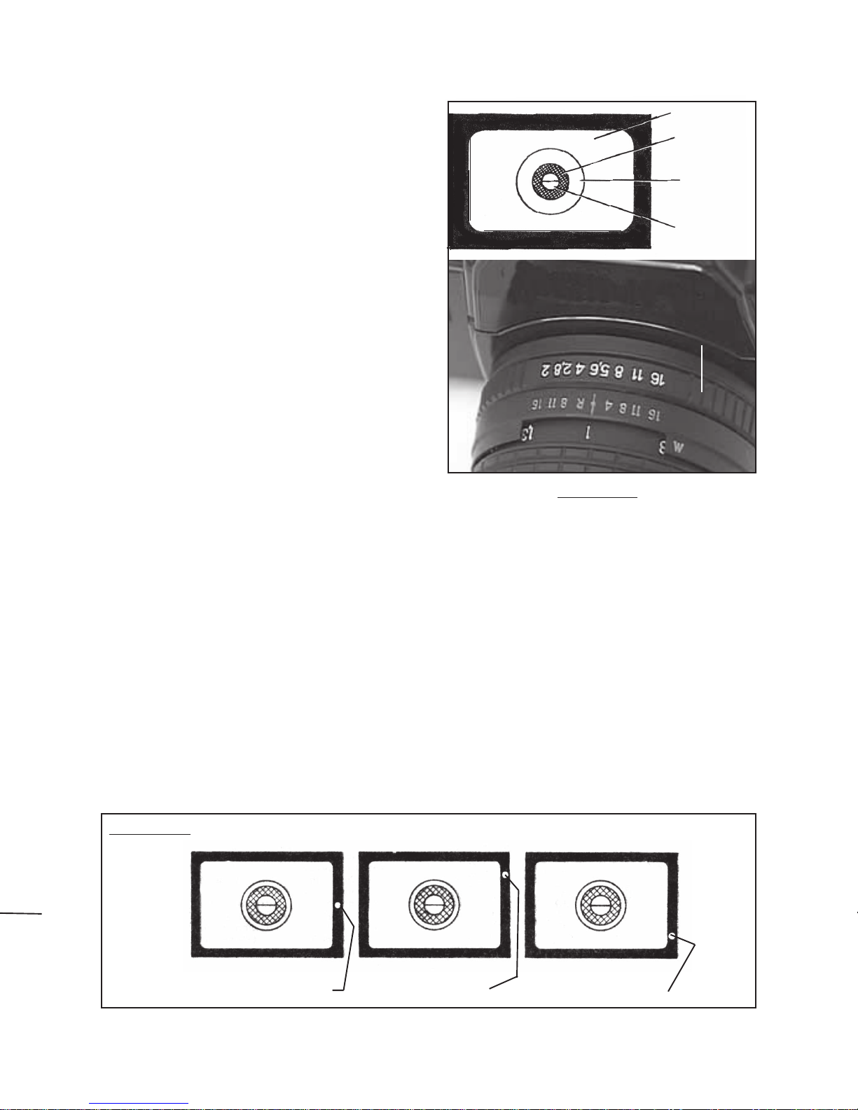
8. The aperture works in conjunction with
the shutter to determine the amount of
light that reaches the Film. The smaller
the aperture value, the larger the aper-
ture opening, and the shallower the
depth of field. Open up the aperture for
portraits, flowers, and other pictures in
which a foreground subject is the main
focal point of the scene. The larger the
aperture value, the smaller the aperture
opening, and the deeper the depth of
field. Stop down the aperture for land-
scapes, document reproduction, and
other pictures where you want to keep the overall picture in clear focus. Set the
aperture with the Aperture Ring (33) on the Lens (31). NOTE: When taking
pictures with the Self-Timer, this procedure is slightly different as described in the
“Self-Timer” section on page 11. (See Figure M.)
APERTURE
RING
(33)
SHUTTER
SPEED
DIAL
(30)
SHUTTER
BUTTON
(29)

SKU 91286 PAGE 10
9. The
Fresnel Lens
in the Camera’s
Viewfinder is equipped with a compos-
ite focusing device consisting of a
Microprism Collar, Ground Glass,
and
Focusing Wedges
. Remove the
protective Lens Cap and look through
the Viewfinder. Turn the Focusing
Ring (32) on the Lens (31) to obtain a
sharp image of the object within the
Ground Glass and Microprism Collar
and to match the upper and lower parts
of the split image with the Focusing
Wedges.
The best sharpness is obtained when
focusing is done at full aperture. Also,
it should be noted that the Focusing
Wedges and Microprism Collar, en-
suring the best possible focusing, are
of no use when interchangeable lenses
are used and focusing is done at aper-
tures more than 4. In these cases as well as in photomicrography and macro
photography focusing should be done on the Ground Glass. (See Figure N.)
10. By making use of various combinations of aperture and shutter speed values,
you can set the exposure depending upon the
brightness of an object
and the
speed of film
being used with a high degree of accuracy. Look through the
Viewfinder in such a way that the entire frame can be clearly seen. Press the
Shutter Button (29) until a definite stop is felt but that the Shutter Button does not
“fire”. While holding the Shutter Button in this position the Viewfinder light-
emitting diodes can be seen. Lighting of the upper (red) diode indicates over-
exposure. Lighting of the lower (red) diode indicates under-exposure. Turn the
Aperture Ring (33) and Shutter Speed Dial (30) until the middle (green) diode is
lighting continuously. This indicates the best possible combination of the shutter
speed and aperture, providing for correct exposure. (See Figure O.)
FRESNEL
LENS
MICROPRISM
COLLAR
GROUND
GLASS
FOCUSING
WEDGES
FIGURE N
FOCUSING
RING
(32)
UNDER-EXPOSURE
(DIODE IS RED)
OVER-EXPOSURE
(DIODE IS RED)
PROPER EXPOSURE
(DIODE IS GREEN)
FIGURE O

SKU 91286 PAGE 11
11. Having prepared the Camera for picture
taking, pull out the Shutter. Make sure of
proper focusing, framing, and exposure.
Then,
smoothly
press the Shutter Button
(29) to take a picture. NOTE:
Sharp
pressure on the Shutter Button will
result in the Camera shaking at the mo-
ment of exposure, causing a blurring of
the picture especially at the shutter speed
of 1/30 s. When taking the picture make
sure that the index mark on the Shutter
Button lines up between the “T” and “V”
settings. FIGURE P
To photograph at high shutter speeds use a tripod with a cable release (neither
included). When screwing the cable into the Camera, the index mark on the
Shutter Button should be turned to the “V” setting. (See Figure P.)
VT
12. To use the Self-Timer feature; Mount the
Camera on a tripod (not included). Press
the Shutter Button (29) until a definite stop
is felt, and turn the Shutter Button clock-
wise to the “V” position. This will enable
you to set the aperture manually since the
diaphragm does not operate automatically
when the Self-Timer is used. Set the
aperture and set the shutter speed. Cock
the Shutter. Wind the Self-Timer by turn-
ing the Self-Timer Dial (23) downwards.
(See Figure Q.) FIGURE Q
13. The red light in the Self-Timer Window
indicates the Self-Timer mechanism
is not
cocked. The green light indicates the
Self-Timer mechanism
is
cocked. Press
the Self-Timer Release Button (24) and
take your position in front of the Camera
Lens. The Shutter Button will operate
seven seconds after pressing the Self-
Timer Release Button. When the Self-
Timer operation is over, return the Shutter
Button to its home position.
(See Figure R.)
SELF-TIMER
DIAL
(23)
FIGURE R
SELF-TIMER
RELEASE BUTTON (24)
SELF-TIMER WINDOW
SHUTTER BUTTON (29)

SKU 91286 PAGE 12
14. When the Frame Counter (27) shows
the figure 36 (if using a 36 exposure film
cartridge), rewind the Film into the
left compartment of the Camera. To
do so, press the Shutter Button (29)
to release it. Press the Film Rewind
Knob (40) down as far as it will go.
Rotate the Rewind Crank (25) in the
arrow direction (shown on the Film) un-
til the Film leaves the Take-Up Spool on
the right compartment of the Camera.
Rotate the Rewind Crank slowly and
smoothly, without jerks. Pull the Film
Rewind Knob (40) all the way up.
Open the back door of the Camera,
and remove the Film cassette. Turn the
Shutter Cocking & Film Advance Lever
(28) while holding the sprocket teeth
of the Take-Up Spool to ensure that it is
engaged. NOTE: Do not attempt to take
more than 36 pictures (if using a 36
exposure film cartridge). However, if it
has happened, and the Film is stuck in
the cassette preventing full Shutter
Button (29) cocking, unload the Camera
in the following way: press the Film
Rewind Knob (40) and hold it down while completely rewinding the Film into the
cassette. Cock and fire the Shutter Button with lens covered. Then, press the
Shutter Button to reset the Frame Counter (27) to “0”. (See Figures S andT.)
15. To use the MC TAIR-3S 300MM Lens (3), carefully unscrew and remove the
MC HELIOS 44M-6 58MM Lens (31). Make sure the 58mm Lens is covered with
its protective Lens Cap and stored safely in the Carrying Case.
(See Figures C and U.)
FIGURE S
SHUTTER
BUTTON
(29)
FILM REWIND KNOB (40)
MC TAIR-3S 300MM LENS (3)
FIGURE U
FIGURE T
SHUTTER
COCKING
& FILM
ADVANCE
LEVER
(28)
FILM REWIND KNOB (40)
LENS
HOOD
(4)

SKU 91286 PAGE 13
16. Carefully screw the 300MM Lens (3) firmly onto the Camera (1). Then, carefully
screw the Lens Head (4) onto the 300MM Lens. (See Figure U.)
17. Attach the Pistol Grip (41) to the
300MM Lens (3) and Camera (1).
To do so, screw the Push Screw Re-
lease (17) on the Pistol Grip into the
tap-hole at the bottom of the Lens.
(See Figure V.)
FIGURE V
PUSH SCREW RELEASE (17)
18. Screw the Clamping Screw (8) on
the Pistol Grip (41) into the base of
the Camera (31). (See Figure W.) CLAMPING
SCREW
(8)
FIGURE W
FIGURE X
19. Insert the Connecting Wire (2) at the
rear of the 300MM Lens (3) into the
socket on the left side of the Camera
(1) bottom. (See Figure X.)
CONNECTING
WIRE
(2)

SKU 91286 PAGE 14
20. NOTE: Squeezing the Trigger (6) on the
Pistol Grip (41) causes the Shutter Release
Button (42) to be automatically depressed.
(See Figure Y.)
FIGURE Y - BOTTOM VIEW
(WITHOUT PISTOL GRIP)
SHUTTER
RELEASE
BUTTON
(42)
21. Operating the Camera with the 300MM Lens
(3) is basically the same as when operating
the Camera with the 58MM Lens (31).
However, when the aperture is set on the
300MM Lens the Aperture Setting Knob (11)
has to be turned first in the direction of the
arrow until it stops. (See Figure Z.)
FIGURE Z
APERTURE
SETTING
KNOB
(11)
22. Select the aperture with the Aperture Setting
Ring (12). NOTE: Figure Z depicts a full
aperture. (See Figure Z-2.)
APERTURE SETTING RING (12)
FIGURE Z-2

SKU 91286 PAGE 15
23. Pulling the Trigger (6) once gives a
preview in the Viewfinder. Pulling
the Trigger again causes the shutter
to be released. (See Figure Z-3.)
FIGURE Z-3
TRIGGER (6)
24. To focus, use the Focusing Drum (20)
in combination with the Distance
Scale (21) located at the bottom of
the 300MM Lens (3).
(See Figure Z-4.)
FIGURE Z-4
FOCUSING
DRUM (20)
DEPTH-OF-FIELD TABLE OF THE MC TAIR-3S (f=300mm)
NOTES 1. D = Distance in Meters (Distance from the film plane to the object.
2. In depth-of-field calculation, the circle of confusion was accepted to be equal to 0.05 mm.

SKU 91286 PAGE 16
25. To attach the Shoulder Stock (10), loosen the Shoulder Stock Clamp (9). Insert
the Shoulder Stock in the Shoulder Stock Chamber (14). Then, firmly tighten the
Shoulder Stock Clamp. (See Figure Z-5.)
26. Connect each end of the Carrying Strap (43) to the two Strap Eyelets (15).
(See Figure Z-5.)
27. The Photo Sniper Camera is now fully assembled and ready for use.
CARRYING
STRAP
(43)
FIGURE Z-5
SHOULDER
STOCK
(10)
SHOULDER
STOCK
CLAMP
(9)
SHOULDER
STOCK
CHAMBER
(14)
STRAP
EYELET
(15)
STRAP
EYELET
(15)
INSPECTION, MAINTENANCE, AND CLEANING
1. Before each use, inspect the general condition of the Photo Sniper Camera.
Check for broken, loose, or missing parts, and any condition that may affect the
proper operation of the product. If a problem occurs, have the problem corrected
before further use. Do not use damaged equipment.
2. For specific maintenance and cleaning procedures, refer to the section
“Specific Product Warnings and Precautions”
on page 3.
PLEASE READ THE FOLLOWING CAREFULLY
THE MANUFACTURER AND/OR DISTRIBUTOR HAS PROVIDED THE PARTS LIST AND ASSEMBLY DIAGRAM IN THIS MANUAL
AS A REFERENCE TOOL ONLY. NEITHER THE MANUFACTURER OR DISTRIBUTOR MAKES ANY REPRESENTATION OR
WARRANTY OF ANY KIND TO THE BUYER THAT HE OR SHE IS QUALIFIED TO MAKE ANY REPAIRS TO THE PRODUCT, OR
THAT HE OR SHE IS QUALIFIED TO REPLACE ANY PARTS OF THE PRODUCT. IN FACT, THE MANUFACTURER AND/OR
DISTRIBUTOREXPRESSLYSTATESTHATALLREPAIRSANDPARTSREPLACEMENTSSHOULD BE UNDERTAKENBYCERTIFIED
AND LICENSEDTECHNICIANS, AND NOT BY THE BUYER. THE BUYER ASSUMES ALL RISK AND LIABILITY ARISING OUT OF
HIS OR HER REPAIRS TOTHE ORIGINAL PRODUCT OR REPLACEMENT PARTSTHERETO, OR ARISING OUT OF HIS OR HER
INSTALLATION OF REPLACEMENT PARTSTHERETO.

SKU 91286 PAGE 17
PARTS LIST
Part
#
Description Qty. Part
#
Description Qt
y
.
1 122S Camera 1 23 Self-Timer Dial 1
2 Connecting Wire 1 24 Self-Timer Release Button 1
3 300 MM Lens 1 25 Rewind Crank 1
4 Lens Hood 1 26 Film Speed Dial 1
5 Tripod Screw 1 27 Frame Counter 1
6 Trigger 1 28 Shutter Cocking & Film
Advance Lever 1
7 Supporting Ring 1 29 Shutter Button 1
8 Clamping Screw 1 30 Shutter Speed Dial 1
9 Shoulder Stock Clamp 1 31 58 MM Lens 1
10 Shoulder Stock 1 32 Focusing Ring 1
11 Aperture Setting Knob 1 33 Aperture Ring 1
12 Aperture Setting Ring 1 34 Light Yellow Filter 1
13 Diaphragm Scale 1 35 Yellow Filter 1
14 Shoulder Stock Chamber 1 36 Green Filter 1
15 Strap Eyelet 2 37 Orange Filter 1
16 Diaphragm Advance
Adjustment Screw 1 38 UV-Haze Filter 1
17 Push Screw Release 1 39 Battery Cap 1
18 Diaphragm Release Lever 1 40 Film Rewind Knob 1
19 Guide Pin Bracket 1 41 Pistol Grip 1
20 Focusing Drum 1 42 Shutter Release Button 1
21 Distance Scale 1 43 Carrying Strap 1
22 Distance Setting Index 1 44 Carrying Case (not shown) 1
NOTE: Some parts are listed and shown for illustration purposes only, and are not
available individually as replacement parts.
Table of contents
Other Harbor Freight Tools Digital Camera manuals