Hardi EZ-Guide Plus User manual

EZ-Guide®
Plus
www.hardi-international.com
67007100 - Version 3.00
GB - 11.2006
Getting Started Guide

Illustrations, technical information and data in this book are to the best of our belief correct at the time of prin-
ting. As it is HARDI INTERNATIONAL A/S policy permanently to improve our products, we reserve the right to
make changes in design, features, accessories, specifications and maintenance instructions at any time and wit-
hout notice.
HARDI INTERNATIONAL A/S is without any obligation in relation to implements purchased before or after such
changes.
HARDI INTERNATIONAL A/S cannot undertake any responsibility for possible omissions or inaccuracies in this
publication, although everything possible has been done to make it complete and correct.
As this instruction book covers more models and features or equipment, which are available in certain countri-
es only, please pay attention to paragraphs dealing with precisely your model.
Published and printed by HARDI INTERNATIONAL A/S
We congratulate you for choosing a HARDI plant protection product. The reliabi-
lity and efficiency of this product depend upon your care. The first step is to
carefully read and pay attention to this instruction book. It contains essential
information for the efficient use and long life of this quality product.

EZ-Guide® Plus
Table of Contents
What
’
s in the EZ-Guide Plus Box? ........................................................................................................................................................................4
Accessories and Upgrades .......................................................................................................................................................................................4
Getting Started ................................................................................................................................................................................................... 6
Parts of the EZ-Guide Plus Lightbar ..................................................................................................................................................................6
Using the Lightbar ..........................................................................................................................................................................................................6
Configuring the Lightbar ..........................................................................................................................................................................................9
Coverage Area .................................................................................................................................................................................................................11
Status Text ...........................................................................................................................................................................................................................11
Getting Guidance .........................................................................................................................................................................................................12
Resetting Guidance. ...................................................................................................................................................................................................12
Configuring the Swath Width .............................................................................................................................................................................12
Using Guidance Patterns ........................................................................................................................................................................................13
Nudge ....................................................................................................................................................................................................................................17
Pause and Resume ......................................................................................................................................................................................................18
Speed Pulse Output ...................................................................................................................................................................................................18
Configuring Guidance Settings .........................................................................................................................................................................18
Guidance Settings ........................................................................................................................................................................................................19
Warning Options ...........................................................................................................................................................................................................19
Using GPS ...........................................................................................................................................................................................................................21
Integrated GPS ................................................................................................................................................................................................................21
Non-Integrated GPS Option ................................................................................................................................................................................23
Viewing GPS Receiver Information .................................................................................................................................................................23
Getting a Clear View of the Sky .........................................................................................................................................................................23
Overview of the Menu .............................................................................................................................................................................................24
T
roubleshooting ............................................................................................................................................................................................................27
Introduction
Welcome to the EZ-Guide Plus Lightbar Guidance System Getting Started Guide.
T
his document describes how to use
the EZ-Guide® Plus lightbar guidance system.
T
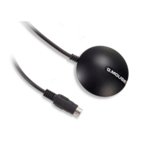
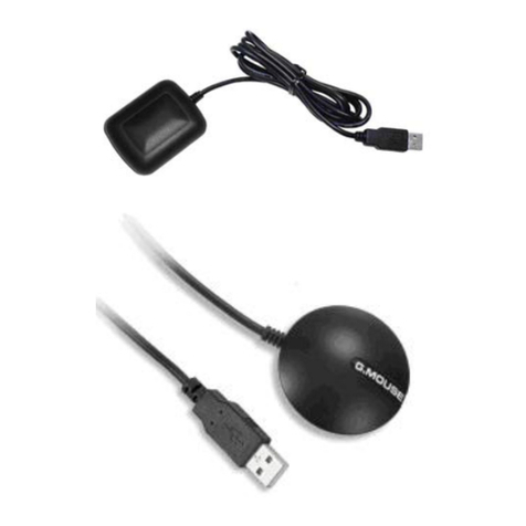
he EZ-Guide Plus lightbar guidance system is a lightbar with an integrated LCD screen and optional integrated GPS
receiver.
3

EZ-Guide® Plus
What’s in the EZ-Guide Plus Box?
When you receive your EZ-Guide Plus system, check that you have
received all the components, as detailed on the packing list. The fol-
lowing diagram shows the standard components.
Note — The antenna, antenna cable, magnetic mount, and metal
plate are included only if you purchased the system with integrated
GPS.
Caution — Keep the lightbar dry. Do not spray the lightbar with any
type of liquid as this will cause it to fail.
Inspect all contents for visible damage, such as scratches or dents. If
any components appear damaged, notify the shipping carrier. Keep
the shipping and packaging material for the carrier’s inspection.
Installing the System
1. Assemble the bracket kit. The bracket is reversible to optimize it for tilt angle. For more information, refer to
the instruc- tions in the bracket kit.
2. Attach the suction cup to the bracket.
3. Attach the power cable to the lightbar.
4. Mount the lightbar in the required position on the window. See Mounting the lightbar.
5. Attach the antenna to the magnetic mount.
6. Connect the antenna cable to the antenna and route the cable to the cab.
7. Attach the magnetic mount to the cab roof, along the vehicle centerline. Do one of the following:
– If the cab roof is steel, attach the magnetic mount directly to the roof.
– If the cab roof is not steel, attach the metal plate to the cab roof. Then attach the magnetic mount to the metal plate.
8. Connect the antenna cable to the lightbar.
9. Plug the power cable into the vehicle cigarette lighter. See Using the vehicle cigarette lighter, page 3.
4

EZ-Guide® Plus
Mounting the lightbar
Caution — The suction cup mount is a temporary mounting device. Before you use it,
read the manufacturer’s instructions provided with the mounting kit.
1. Dampen the rubber seal on the suction cup.
2. Place the suction cup on a clean section of window, and then pump the plunger until its red line is no longer visible.
In addition:
• To ensure that the lightbar stays securely attached, pump the suction cup each day, or whenever the red line appears
on the plunger.
• If the lightbar does not stay securely attached with the suction cup, you can glue the cup to the window. Or, attach the
lightbar bracket directly to the dash, ceiling, or window.
Using the vehicle cigarette lighter
If the power cable is plugged into a cigarette lighter that is not wired through the vehicle ignition, the lightbar receives
power whenever the cable is plugged in. To avoid draining the vehicle battery, turn off or disconnect the lightbar from
the power source if the vehicle will be unused for an extended time.
Minimizing GPS signal interference
T
o minimize any interference to the GPS signal, make sure that the GPS antenna is at least 1 m (3 ft) from any other
antenna (including a radio antenna), and at least 100 m (300 ft) from any power line, radar dish, or cell phone tower.
Connecting other devices
• To use the remote control or an external GPS receiver or an exter- na
sensor (for example, yield monitor), attach it directly to the lightbar
data port connector.
• To use the remote control and an external receiver or sensor, con-
nect them using the optional external interface cable.
• To connect a spray switch or device to receive speed pulse out-
puts, use the optional external interface cable.
Note — You cannot connect an external GPSreceiver and external
sensor at the same time.
Note — Connect the device to receive speed pulse outputs to con-
nector "A", a spray switch to connector "C", and the ground wire(s) to
connector "B" using the connector kit and instructions provided
with the kit. Do not supply power to the switch inputs.
5

EZ-Guide® Plus
Getting Started
T
his section describes how to
g
et started with the EZ-Guide Plus li
g
htbar
g
uidance s
y
stem. For in
f
ormation on usin
g
g
ui-
Parts o
f
the EZ-Guide Plus Lightbar
T
he following picture shows the main hardware features of the EZ-
Guide Plus lightbar.
1. Integrated GPS receiver (optional) High-performance
Integrated WAAS/EGNOS/MSAS receiver
• EVEREST™ multipath rejection technology
2. Buttons Three buttons to operate the lightbar:
• OK Action selected icon, accept changes
• A Select icon, increase configuration value
• V Select icon, decrease configuration value
3. Guidance LEDs Provide offline guidance to the closest swath
4. LCD display
• Monochrome
• Anti-glare screen
• Multi-level backlight
5. Data port
• GPS output
• External GPS input
• External correction input
• GPS diagnostics and configuration
• Pulse output and switch input (requires external interface cable)
Using the Lightbar
Main screen items
T
he following picture shows the items on the main map screen.
1. Status text (top)
2. Action icon bar (side)
3. Tips (bottom)
6

EZ-Guide® Plus
EZ-Guide Plus installation
West o
f
EU Settings (ESTB Area)
FW Version 2.0x & 3.xx
From Default settings
1) Select the Language
2) Select the Units
3) Lk ahead Default is 1s
1s 0 to 10 km/h
2s 11 to 15
3s 16 and more
4) Keep antenna offset set to default 0 cm default is 0 cm
Ez-Guide Plus
East of EU Settings
FW Version 2.0x & 3.xx From Default settings
1) Select the Language
2) Select the Units
3) Turn Corrections to OFF
4) Set Low accuracy warning to No Warning
5) Lk ahead Default is 1s
1s 0 to 10 km/h
2s 11 to 15
3s 16 and more
6) Keep antenna offset set to default 0 cm
7

EZ-Guide® Plus
Action icons
T
o select an icon, press Aor V, then press o. These action icons can be displayed in the icon bar:
Icon Description
9 Reset guidance
A Set Point A
B Set Point B
8 Start headland
D Final headland
7 Go to main configuration menu
1 Nudge left
3 Nudge right
2 Pause/Resume
4 Change views
5 Zoom
Note — Some action icons may not be available until a field is defined.
Views
T
o change between the three views, select
Perspective map
T
his is the default screen for guidance. It displays two status text
options.
Plan map
T
his is the default screen when you:
• define the field
• pass the end of the swath
• move offline by more than half a swath
• pause guidance
I
di l
i
Bill d
48/55
8

EZ-Guide® Plus
Status
T
his screen displays up to four status text options.
T
o configure the text, use the Status Text configuration option.
Zooming
T
o enter zoom mode, select 5, or press z on the
remote control. The ZOOM screen appears.
• To change the zoom scale, press A or V.
• To accept zoom scale and return to the map view,press o, or press
z on the remote control.
Configuring the Lightbar
Before you use the lightbar in the field, check and configure the lightbar settings from the Lightbar menu:
1. To access the configuration menu, select 7 and then press o. Or press m on the remote control.
2. To select a configuration option and display the value, press u or D. To accept the setting, press o.
3. To change the value, press u or D. To save the change, press o.
4. To exit the configuration menu, press u or D until you have selected the Return to Guidance option, and then press o.
Or press m on the remote control.
Adjusting the brightness and contrast
You can view the LCD screen in all conditions—from bright sunlight
to night time.
If necessary, use Lightbar / Contrast / Brightness to adjust the screen
contrast, turn on the backlight, or adjust the backlight and LED
brightness.
Tip — If the backlight is configured to On, it automatically turns off
during daylight hours, and turns back on in the late afternoon. When
the backlight is enabled but currently not on, the Backlight setting
displays Auto.
9

EZ-Guide® Plus
Setting the units and language
T
o change:
• the units to metric, use Lightbar / Units
• the language to Portuguese, Spanish, French, German, or Italian, use Lightbar / Language
Changing the display orientation
By default, the lightbar displays correctly when it is mounted with
the LEDs above the screen (upright).
T
o configure the lightbar to display correctly when it is mounted
with the LEDs below the screen (inverted), use Lightbar / Lightbar
Mount.
Configuring the display
Use Lightbar / Display Config to enable or disable any of the follo-
wing items displayed on the plan and perspective maps:
• Progress Lines: To give a sense of perspective and speed
• Adjacent Swaths: One swath either side of the current swath
• Field Boundary: If the field is a Headland
• AB Line
• Path Driven
You can also use this screen to change the View option:
• Auto: View automatically changes between plan and perspective
views in headlands
• Fixed: View remains fixed
Path display
By default, the path you have driven is always displayed on screen as
a dotted line. If you have a spray switch connected, you can choose
to display the path only when the spray switch is on. To do this, con-
figure Path Display to Switch.
T
o turn off the display of the driven path, configure Path Display to
Off.
10

EZ-Guide® Plus
Setting the antenna offset
By default, the antenna is assumed to be at the implement position.
If the antenna is not mounted at the implement position, to ensure
correct guidance, set an antenna offset using Lightbar / Antenna
Offset.
1. Antenna offset ahead of implement
2. Vehicle centreline
3. Implement
Caution — The antenna must be mounted on the vehicle centerli-
ne. Otherwise, offline guidance will not be correct.
Coverage Area
Coverage area is calculated whenever the spray switch is connected and on. For information on connecting a spray
switch, see Connecting other devices.
By default, Coverage Area is configured for display on the Status screen. To display Coverage Area on a map view instead,
use Lightbar / Status Text.
T
o save the coverage area value, you must Pause before turning the system off. Otherwise the value will be lost when you
restart the system.
Status text
Status text Definition
Swath number Swath number of the closest swath.
Offline distance Distance offline from the closest swath.
Speed Current speed.
Heading Current heading.
Field area Area of the field calculated half a swath width outside the path driven. A value is displayed
only for Headland patterns.
Satellites Number of GPS satellites used.
HDOP Horizontal Dilution of Precision. This is a measure of accuracy based on the geometry of the
satellites in the sky. An HDOP of 2 or less is good.
Height Current antenna height above mean sea level (MSL).
GPS status Current GPS status.
Coverage area Area applied while spray switch was on. Calculated as distance x swath width. To save the
coverage area value when turning off the system, pause guidance before disconnecting
power.
Nudge Displays accumulated nudge perpendicular to the direction of travel.
None No status text displayed.
11

EZ-Guide® Plus
Getting Guidance
T
he EZ-Guide Plus lightbar guidance system provides the following pattern options:
Pattern Definition
AB Line Straight guidance based on A and B points that define the initial line.
A+ Straight guidance based on an A point and the previous line heading.
Identical curve Curve guidance based on the initial curve.
Adaptive curve Curve guidance based on the last curve driven.
Headland Records headlands of any shape as you drive around the field. Can provide guidance on multiple
headland passes and straight swath guidance inside the headlands.
For more information, see Using Guidance Patterns, page 11.
Note — For best possible GPS accuracy, wait for 15 minutes after you turn on the EZ-Guide Plus lightbar each day.
T
hi
s
allows time for the WAAS almanac data to be downloaded. If you set an AB Line before the WAAS almanac is downloa- ded
,
you can get significant position drifts within that first 15 minutes.
Resetting Guidance
1. Select 9. The Guidance Pattern screen appears.
2. Press u or D to choose the required pattern and then press o.
A message appears asking you to confirm your choice.
This prevents accidental resetting of the guidance pattern.
3. To confirm, press o.
Configuring the Swath Width
Once you select a pattern, the Swath Width screen appears:
• To change the swath width, press u or D.
• To accept the swath width, press o.
Tip — Set the swath width to 0.3 m (1 ft) less than the total imple-
ment width, to avoid skips between swaths.
12

EZ-Guide® Plus
Using Guidance Patterns
T
his section describes how to define and use each of the available swath patterns.
T
he AB Line is a line that runs between Point A and Point B, although you may not always set a Point B. In most cases, the
AB Line is the reference line for subsequent swaths.
T
he start and end of the initial swath that defines the swath pattern appear on the lightbar screen as a circle (Point A)
and a square (Point B).
Swaths drawn on screen extend 1 km (0.62 mi) beyond Point A and Point B, and the extensions appear as dotted lines.
T
his
makes it easier to see where the next swath is, and to get online after the turn.
Note — The initial swath (AB Line) appears as a thin, solid line; the current swath appears as a bold line.
AB Line pattern
Use the AB Line pattern when no headlands are required and you
drive the field in parallel straight lines.
1. At the start of the first swath, map Point A.
2. Drive to the other end of the field, and at the end of the first
swath, map Point B.
3. Turn left or right for the next swath. The next swath is
automatically selected.
4. Steer the vehicle so that you center the green lights in the
lightbar as you drive forward along the swath.
Tip — Set Point B part way down the swath to get guidance down
the first pass, and then reset Point B at the end of the field.
A+ pattern
Use the A+ pattern when you need guidance exactly parallel to the last
AB Line, for example:
• adjacent fields
• map the AB Line on a road down the side of the field
• skip an access road in a field
1. To map the start of the first swath, map Point A.
The heading of the AB Line equals either the previous AB heading
or the manually entered heading (if the current vehicle heading is
wit- hin +/-90 degrees of the AB heading). Otherwise the A+
heading is in the opposite direction.
2. Follow the AB Line for guidance down the first swath.
3. Turn left or right for the next swath. The next swath is
automatically selected.
4. Steer the vehicle so that you center the green lights in the lightbar
as you drive forward along the swath.
13

EZ-Guide® Plus
Identical curve pattern
Use the Identical curve pattern when you want to work the field
with gentle curves. This pattern provides guidance based on the ini-
tial curve. It ignores any deviation around an obstacle.
1. At the start of the first swath, map Point A.
2. Drive the initial curve. At the other end of the first swath, map
Point B.
3. Turn left or right for the next swath. The next swath is automatical-
ly selected.
4. Steer the vehicle so that you center the green lights in the
lightbar as you drive forward along the swath.
Adaptive curve pattern
Use the Adaptive curve pattern to follow gentle contours in th
e
field, or when you need to avoid obstacles. This pattern provide
s
guidance based on the last curve driven.
Simple Curves
T
o drive simple adaptive curves:
1. At the start of the first swath, map Point A.
2. Drive the initial curve.
3. Turn left or right for the next swath. The next swath is
automatically selected.
4. Steer the vehicle so that you center the green lights in the
lightbar as you drive forward along the swath.
Note — By default, the end o
f
the swath is automatically detected when you do a U-turn. I
f
you pre
f
er to manually mar
k
the end of each swath, from the configuration menu, select Guidance / Auto-detect Turn and change to Off. You must
then reset Point B at the end of every pass, to mark the end of the swath before you start the turn.
C-clamp
T
o use the adaptive curve pattern to get C-clamp guidance with the
default of Auto-detect Turn set to On, do the following:
1. At the start of the headland, map Point A.
2. Drive around the headland in a C-clamp pattern.
3. Turn left or right for the next swath. The next swath is automati-
cally selected.
4. Steer the vehicle so that the green lights in the lightbar are cente-
red as you drive forward along the swath.
Note — The bold lines on the graph show where you must drive
without guidance.
14

EZ-Guide® Plus
Spiral
T
o use the adaptive curve pattern to get spiral guidance into the
center of the field:
1. From the Guidance menu, select Autodetect Turn to Off.
2. Start a new field using the Adaptive Curve pattern.
3. At the start of the headland, map Point A.
4. Drive around the headland.
5. When you are nearly back at Point A, map Point B.
6. Turn into the field. The next swath is generated off the last pass.
7. On each pass, when you are nearly back to where you started the
headland, reset B to mark the end of the swath.
Note — Make sure that you are not within one swath width of the
start point. If you are, Point B will not be set.
Headlands pattern
Use the Headlands pattern when:
• you need to apply the headland area first, to give you room to turn when you apply the straight swaths
• you want to know the area of the field You can do as many headland circuits as required before you change to straight
swaths. The headlands pattern automatically increments to the next headland when you enter the circle around the
start point of the headland.
Single headland
1. Start the headland.
2. Drive around the field area. The headland is recorded.
3. Identify the current headland circuit as the final one.
The head- land is still recorded until you reach the circle around
the start point.
4. To map the start of the first straight swath, map Point A.
Note — Do this before you enter the circle around the start point or
map A and B points.
5. Drive to the other end o
f
the field and map Point B.
6. Enter the circle around the start point of the headland to complete the headland. The area is then displayed.
7. Turn left or right for the next swath. The next swath is automatically selected. Steer the vehicle to center the green
lights in the lightbar as you drive forward along the swath.
Note — Straight swaths automatically fill the headland boundary. The AB Line does not need to be the full length of the
field.
15

EZ-Guide® Plus
Multiple headlands
1. Start the headland.
2. Drive around the field area. The headland is recorded.
3. When you return to the headland start point, the next headland
swath is automatically generated.
4. Identify the current headland circuit as the final one. You must do
this before you enter the circle around the start point or map A a
n
B points.
You continue to receive guidance to the final headland until you
drive off the pass by half a swath.
5. To map the start of the first straight swath, map Point A at any
time.
6. Drive to the other end of the field then map Point B.
7. Turn left or right for the next swath. The next swath is automati-
cally selected.
8. Steer the vehicle to center the green lights in the lightbar as you
drive forward along the swath.
Note — Straight swaths automatically fill the headland boundary.
T
he AB Line does not need to be the full length of the field.
Center-pivot pattern
Use the Center-pivot pattern for a field that is irrigated using a cen
-
ter-pivot. With this pattern, you can drive concentric circles aroun
d
the center-pivot.
Note — To work from the center of the field outwards, the initial
pivot must have:
• a radius of at least two swath widths
• an arc length of at least two swath widths
1. Position one wheel of the vehicle in a pivot wheel rut, with the
rear of the vehicle to the pivot arm (or to the edge of the field, i
f
the field is not a full circle pivot).
2. To start the pivot, map Point A.
3. Drive around the field. Keep the vehicle wheel in the rut. The
lightbar does not yet provide guidance.
4. When you are almost back to the pivot arm or the edge of the
field, map Point B.
EZ-Guide Plus generates guidance swaths.
5. Turn left or right for the next swath. The next swath is automati-
cally selected.
6. Steer your vehicle so that you center the green lights in the
lightbar as you drive forward along the swath.
Note — You must drive at least half a circle before you can set the
end of the pivot.
Once you define the pivot, you can drive swaths inside or outside
the first swath.
16

EZ-Guide® Plus
Nudge
Use nudge to move the guidance line back to the correct path to:
• correct for GPS position drift when returning to the field for guidance, for example after pausing or turning the unit off a
on
• correct for GPS satellite constellation changes while driving in the field.
On the ground –
Vehicle on line with current swath/row.
On screen –
Vehicle offline. Nudge left to correct..
Nudge is always applied to the guidance line relative to the vehicle heading.
T
o nudge, select 1 or 3. Each nudge moves the guidance line 3 inches. For example, if you press 3 twice, the total nudge
distance is 6 inches to the right.
T
o display the total accumulated nudge perpendicular to the current vehicle heading, use Lightbar / Status Text.
Configure Nudge to appear on a map view or Status screen.
T
o reset the nudge distance to 0, select Guidance / Reset Nudge.
17

EZ-Guide® Plus
Pause and Resume
T
o pause guidance, select 2 or press p on the remote control. When
you pause guidance:
• The display changes to the Plan View map (if the Display Config /
View option is set to Auto).
• An icon appears at the pause location and indicates the direction
o
pause.
• The pause swath appears on the screen.
• The screen automatically zooms to keep your current position
and the pause icon on the screen. You cannot zoom manually.
• A dotted line joins your current position and the pause point.
• The map status text changes to display the distance to the pause
point and the offline distance from the pause swath.
• The LEDs do not provide offline guidance while you are more
than half a swath from the pause swath.
• Progress lines and adjacent swaths are not displayed.
T
o resume guidance, select 2 or press p on the remote control.
Speed Pulse Output
T
he EZ-Guide Plus lightbar can output speed pulse. This can be used to:
• Replace the radar / true ground speed sensor for speed on the vehicle.
• Send speed to any other agricultural device requiring speed pulses, for example, yield monitor or variable rate control-
ler. For information on connecting a device to the speed pulse outputs, see Connecting other devices, page 3.
T
o enable pulse output, use Lightbar / Pulse Output to select the output rate expected by your device.
Configuring Guidance Settings
You can configure the guidance and warning settings of the EZ-
Guide Plus lightbar guidance system to suit your personal preferen-
ce and your application.
18

EZ-Guide® Plus
Guidance Settings
Configure the following lightbar settings from the Guidance menu.
LED mode
T
here are two LED modes:
Mode Definition
Chase: Chase the lights to stay online. The lights represent the swath location relative to the vehicle.
Pull: Center the lights to stay online. The lights represent the vehicle location relative to the swath.
LED spacing
T
he LED spacing is the distance represented by one LED. Decrease the LED spacing to increase the sensitivity of the LEDs.
Look ahead
Use the look ahead time to predict your future vehicle path to allow for reaction time
and vehicle turn speed. Set the look ahead time in seconds, as shown below:
Speed Look Ahead Time
0–13 kph (0–8 mph) 1 second
13–24 kph (8–15 mph) 2 seconds
24+ kph (15+ mph) 3 seconds
For larger vehicles that take longer to turn, increase the look ahead time.
Note — For 4WD articulated tractors, always set the look ahead time to 0 seconds.
Auto-detect turn
T
his setting is used only for the Adaptive Curve pattern. This setting defaults to On, which means that a new swath is
automatically generated when a U-turn is detected. To manually identify the end of each adaptive curve swath, change thi
s
setting to Off.
Warning Options
Configure the following warning option settings from the Warnings menu. Warnings are displayed as a flashing message
on the screen.
Headland warning
T
he EZ-Guide Plus system displays a message when you pass the
end of the swath. You can also configure a lead time for the head-
land warning so that the EZ-Guide Plus system warns you as you
approach the end of the swath. By default, this is set to 0 sec. To turn
the headland warning off, or to configure the lead time, use the
Headland Warning configuration screen.
Offline warning
T
he EZ-Guide Plus system can display a message when you have gone too far offline. By default, this is set to 0'0" (no
warning). To configure an offline warning, use the Offline Warning configuration screen
19

EZ-Guide® Plus
Low accuracy warning
T
here are three states for a low accuracy warning:
State Definition
High accuracy only Uses only high accuracy positions for guidance. When low accuracy positions are received,
guidance is suspended. The lightbar displays a warning.
Warn low accuracy When low accuracy positions are received, guidance continues normally.
The lightbar displays a warning.
No warning When low accuracy positions are received, guidance continues normally. There is no warning.
Audible warning
If you have a remote control or an alarm connected to the EZ-Guide system, it can emit an audible warning. To enable t
h
audible warning, use the Audible Warning configuration screen.
20
Table of contents
