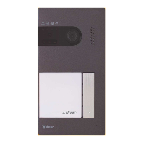
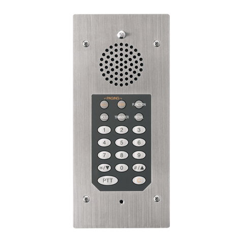
Harding Instruments dxi MicroComm ICM-400 Series User manual

ICM-400 Series Intercom Stations
Document IM-ICM-400-2.14 1999 Harding Instruments - Printed in Canada
1. Intent & Scope
This document describes the installation procedure for the ICM-400 series intercom stations. The ICM-400 series
intercom stations include intercom stations types ICM-420, ICM-421, ICM-430, ICM-431, and ICM-490. The ICM-
4x1 stations include a LED while the ICM-4x0 stations do not. The ICB-400 Intercom Board is used to convert a 45
ohm loudspeaker into a 400 series intercom station. Included is a description on connecting an ICM-420 and ICM-
320 to create a two sided door primary/secondary pair
2. Description
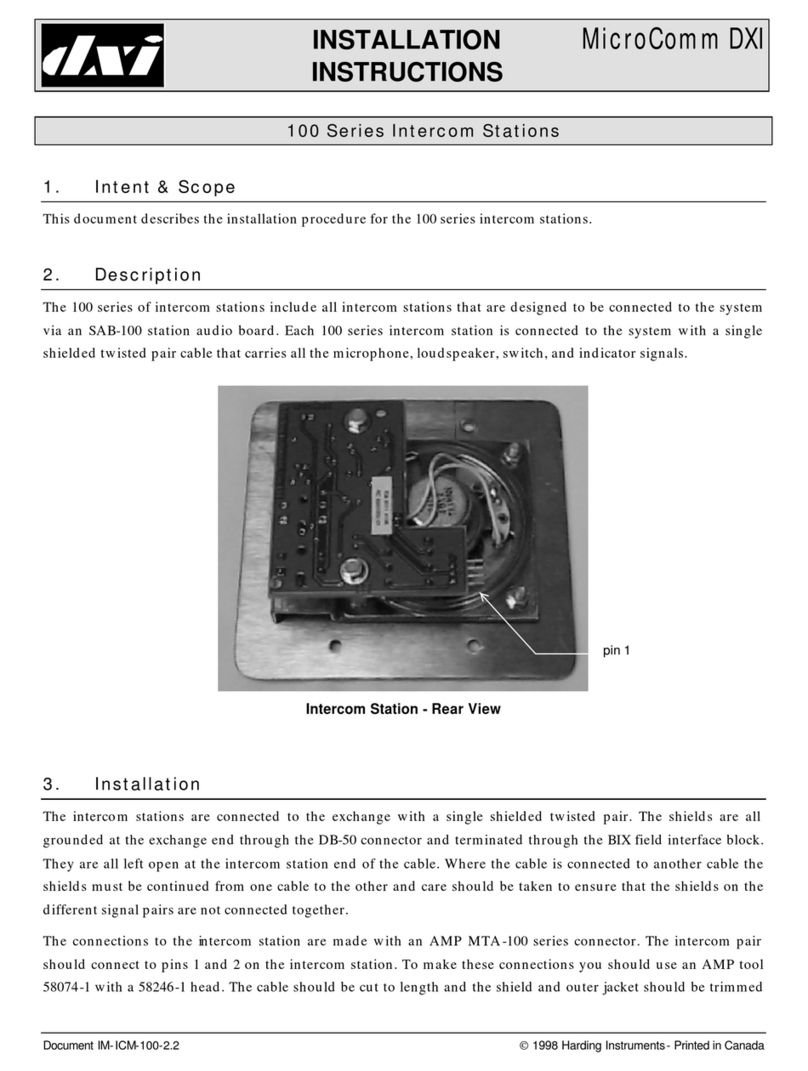
The ICM-400 series of intercom stations include all intercom stations that are connected to a DXI system via a
SAB-400 or SAB-401 station audio board, or to a DXL system via a SCC-400 or SCC-401 station control card. Each
ICM-400 series intercom station is connected to the system with a single shielded twisted pair cable that carries all
the microphone, loudspeaker, switch, and LED indicator signals.
The ICM-400 series intercom stations can be ordered in several configurations. These include:
(i) 0, 1 or 2 switches. These switches are mounted on the faceplate and internally terminated. They can be
used for call request, program music selection, or other functions. The terminations allow the system to
detect open or short line faults.
The switch information is multiplexed with the audio signals over a single pair of wires.
(ii) The LED stations, ICM-421 and ICM-431, are used with SAB-401 station audio board or SCC-401 station
control card. The LED is used to indicate call request status or active call status. Again LED status
information is multiplexed over the audio pair.
(iii) A cord jack can be specified in place of the standard faceplate switch on the intercom stations.
(iv) An Apem switch, red mushroom button switch or mini-piezo switch can be ordered for the intercom
stations.
(v) A piezo-electric switch can be specified in place of the standard faceplate switch on the ICM-430 or ICM-
431
(vi) The switch contacts of a switch can be made available on a four-pin header. With external field wiring the
switch can then be used to operate an external device, i.e. open a door; turn on lights, etc. External
contacts can also be connected to this four-pin header. This allows external equipment to activate the
station switches and place call requests or act as a switch to change the music selection.

ICM-400 Series Intercom Stations
Page 2 Document IM-ICM-400-2.14
(vii) The ICB-400 Intercom Board kit is used to convert a 45 ohm loudspeaker into a 400 type of intercom
station.

ICM-400 Series Intercom Stations
Document IM-ICM-400-2.14 Page 3
Rear View of ICM-420 Intercom Station with connectors CN1 and CN3 installed
3. Installation
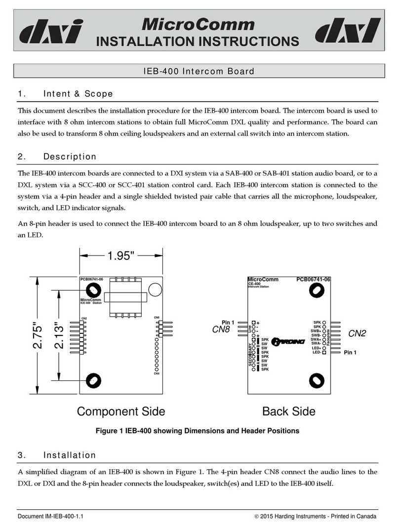
A simplified diagram of the back view of the ICM-420 is shown below. The header CN1 is always present and is
used to connect audio, programmable switch information and LED status between the system and the intercom
station. The audio lines are connected to pins 1 and 2 of CN1 with a 4-pin MTA-100-04 connector. (Note: Since
only two pins on the header are used for the audio connections a 2-pin MTA-100-02 connector may be used.)
The headers labeled CN3 and CN4 are used for optional configurations. Header CN3 is used when Switch B is to
provide an external contact closure. The switch contacts are connected to pins 1 and 2 of the header CN3. Header
CN4 is used when Switch A is to provide external switch contacts. The switch contacts are connected to pins 1 and
2 of the header CN4. Remote contact closures can be transmitted to the system through pins 3 and 4 of CN3 and
CN4.
The possibility of inserting a header labeled CN2 was included on the printed circuit board to permit a handset
and hookswitch to be interfaced to the station. This header is used only on the FDH-420 and FDH-440 handset
stations.
The maximum recommended distance to run 22-gauge twisted-pair shielded cable from a 400 series station to
SAB-400 (or SAB-401) is 2500 feet (750 meters).
Note: In PC board version PC06713-03 the silkscreen pin numbers for CN1 are incorrect, and are given in reverse
order.
CN1
Pin 1
CN3
Pin 1

ICM-400 Series Intercom Stations
Page 4 Document IM-ICM-400-2.14
Aud +
Aud -
Aud -
Aud +
1
2
3
4
10
9
8
6
7
3
2
5
4
1
4
3
2
1
4
3
2
1
Switch B In +
Switch B Out -
Sw B In -
Switch B Out +
Switch A In +
Switch A Out -
Switch A In -
Switch A Out +
SWB
--
+ +
-
-
+SWA +
CN1
CN2
CN3
CN4
Spkr +
Spkr-
4.50"
4.50"
2001 Harding Instrument Co. Ltd.
PC06713-04
Rear View of ICM-420 Printed Circuit Board Showing Header Positions
Header CN1 is always present.
Header CN2 is not present.
Connector CN3 is present if the option allowing Switch B to switch an external device is ordered.
Connector CN4 is present if the option allowing Switch A to switch an external device is ordered.
3.1 Audio Connection from System to Intercom Station
Each intercom station is connected to the exchange with a single shielded twisted pair. This pair is connected to
terminals on the field interface terminal block. In turn these terminals are connected via a twisted pair in a CBL-
190 cable to the SAB-400 (or SAB-401).
All shields are terminated at the field interface teminal block. The shields are grounded through the cable that
connects the terminal block to the DB-37 connector on the SAB-400 (a CBL-190 cable). Note the CBL-190 cable has
3 wires that are connected to ground on the SAB-400/401 (See IM-DXI-REF-MAR05). The shields are left open at
the intercom station end of the cable. Where two twisted pair cable segments are used to make up a cable the
shields must be continued from one cable segment to the other. Care should be taken to ensure that the shields on
the different signal pairs are not connected together, except at the terminal block.
The connections to the intercom station are made with an AMP MTA-100 series connector. The intercom pair
should connect to pins 1 and 2 on a female 4-pin AMP MTA-100 series connector that plugs onto the header
labeled CN1 on the printed circuit board of the intercom station. To make these connections you should use an
AMP Handle Assy 58074-1 tool with a 58246-1 head. The cable should be cut to length and the shield and outer

ICM-400 Series Intercom Stations
Document IM-ICM-400-2.14 Page 5
jacket should be trimmed back about 1/2 inch. Ensure that the shield is not exposed or it may short out exposed
contacts on the intercom PCB when it is installed.

ICM-400 Series Intercom Stations
Page 6 Document IM-ICM-400-2.14
The pin configuration of the station connector is:
MTA Pin
Signal
1
Audio +
2
Audio -
3
N/C
4
N/C
MTA Pin Signals
To insert the signal wires into the connector you remove the white cover from the connector, insert the connector
into the tool from the left side (it will travel through the tool in the direction indicated by the arrow), pull the
trigger once to load the connector. Then insert the signal wire for pin 1 (do not strip the wire) into the hole on the
top of the tool and pull the trigger to insert the wire into the connector. Then repeat to install the other signal wire.
Finally, remove the connector from the tool, replace the cover, and then slide the connector onto the pins on the
intercom station.
3.2 Switch Headers
The standard faceplate mounted switch(es) can be brought out to headers for connection to external devices. The
internal switch contacts are brought out to pins 1 and 2 of the header CN3. An external switch can be connected to
pins 3 and 4 of the header. If the external switch closes the closure will be transmitted to the system in the same
manner as the internal switches on other stations. One or two headers can be installed. CN3 is the header for
Switch B and CN4 is the header for Switch A. The external switch connections to the header(s) are made with a
female 4-pin AMP MTA-100 series connector.
MTA Pin
Signal
1
Switch 1Out +
2
Switch 1 Out -
3
Switch 1 In +
4
Switch 1 In –
4. ICB-400 Intercom Board (Talkback Kit)
The ICB-400 is used to convert a 45-ohm loudspeaker into an intercom station. The ICB-400 can be used with a 45-
ohm loudspeaker without a matching transformer. It may be used to connect an 8 ohm cone type loudspeaker
through a 25 ohm matching transformer at a 5 watt tap. Two 8 ohm speakers may be connected in parallel if each
transformer taps is set at a 2.5 watt tap. With the insulated option the ICB-400 is designed for easy mounting to a
loudspeaker assembly (using Velcro strips). The ICB-400 intercom board is not recommended for use with
compression type loudspeakers.
ICB-400 Intercom Board talkback kits can be installed on standard 8” loudspeakers to permit them to operate the
same as any intercom station. The units have pigtail leads to connect the loudspeaker. These leads are soldered to
the terminals labeled Spkr + and Spkr - shown on the back view of the printed circuit board. The pigtail leads are
24” in length and can be cut to a shorter length if required. The two optional remote switches are connected to
connectors CN3 and CN4 on the printed circuit board (Normally Switch B will be used as a remote call switch).

ICM-400 Series Intercom Stations
Document IM-ICM-400-2.14 Page 7
The switch connections can optionally be ordered as pigtail leads, a 4-pin MTA–100 connector or as a 4-pin MTA-
100 connector with pigtail leads.
Aud +
Aud -
Aud -
Aud +
1
2
3
4
10
9
8
6
7
3
2
5
4
1
4
3
2
1
4
3
2
1
Switch B In +
Switch B Out -
Sw B In -
Switch B Out +
Switch A In +
Switch A Out -
Switch A In -
Switch A Out +
SWB
--
+ +
-
-
+SWA +
CN1
CN2
CN3
CN4
Spkr +
Spkr-
Pigtail leads
to speaker
2001 Harding Instrument Co. Ltd.
PC06713-04
To SAB
2.13"
2.50"
2.73"
ICB-400 intercom Board
If the circuit board is not encased in the non-conductive heat shrink it can be mounted using the two 0.125”
diameter holes shown in the above diagram. You may have to use standoffs to insure all components have
suitable clearance.
If the circuit board of the talkback kit is encased in the optional non-conductive heat shrunk case then it is
attached with two strips of Velcro mounted on the back. Remove the exposed adhesive protective strip from the
Velcro and gently press the talkback kit on to a convenient mounting location on the loudspeaker assembly.
In ICB versions without switch headers printed circuit board traces connect the Sw B (A) In + to the Switch B (A)
Out+ and the Switch B (A) In – to the Switch B (A) Out -.

ICM-400 Series Intercom Stations
Page 8 Document IM-ICM-400-2.14
Talkback Kit Installation Complete
Make the electrical connections to the talkback kit for the loudspeaker and optional switches. The loudspeaker
connection must be made to a 45-ohm loudspeaker, or through a matching transformer. For an 8 ohms speaker a
matching transformer is required. The ideal transformer tap setting of 25 V/13.9 watts will provide an output of 1
watt into an 8 ohm speaker. You should select a transformer tap setting as close to the ideal values as possible.
Selecting a setting of 25 V/10 watts will give an output of 0.97 watts into an 8 ohm speaker, while a transformer
tap setting of 25 V/5 watts will provide an output of 0.77 watts. The pigtail leads for the speaker and switch
connections of the ICB-400 Intercom Board (Talkback Kit) are color coded as follows:
Wire
Signal
Green
Spkr +
Black
Spkr -
Yellow
Switch B In+
Yellow
Switch B In -
Orange
Switch A In +
Orange
Switch A In -
The intercom talkback unit is connected to a station audio board the same as any other intercom station via the
MTA connector. The following table gives the pin configuration for the MTA connector.
MTA Pin
Signal
1
Audio +
2
Audio -
3
N/C
4
N/C
Connections to
transformer from
Spkr+ and Spkr-
Trim and insulate
unused switch
leads
Trim and insulate
unused transformer tap
leads

ICM-400 Series Intercom Stations
Document IM-ICM-400-2.14 Page 9
5. Two Sided Door Primary/Secondary Pair
The two sided Door Primary/Secondary paired stations are meant to provide an intercom on both sides of a door
but require only one SAB channel. This is achieved by paralleling the speaker and switch of the secondary station
to the circuitry of the primary station. The following diagram shows the necessary connections. The center two
pins of the 4-pin MTA connector CN2 (labeled 8 and 9) of the secondary station are connected to the center two
pins of the 4-pin MTA connector CN2 on the primary station. The lower two pins of the 4-pin MTA connector
CN3 (labeled 1 and 2) of the secondary station are connected to the corresponding lower two pins of the 4-pin
MTA connector CN3 on the primary station.
Aud +
Aud -
Aud -
Aud +
1
2
3
4
10
9
8
6
7
3
2
5
4
1
4
3
2
1
4
3
2
1
Switch B In +
Switch B Out -
Sw B In -
Switch B Out +
Switch A In +
Switch A Out -
Switch A In -
Switch A Out +
SWB
--
+ +
-
-
+SWA +
CN1
CN2
CN3
CN4
Spkr +
Spkr-
2001 Harding Instrument Co. Ltd.
PC06713-04
CN1
Switch A In +
3
Switch A Out +
Switch A Out -
CN4
1
2
2001 Harding Instrument Co. Ltd.
7
CN2
Switch A In -
Switch B Out +
Sw B In -
Switch B Out -
Switch B In +
CN3
1
4
3
2
4
4
2
1
3
5
6
Aud +
Aud -
Aud -
Aud +
4
9
8
10
Spkr-
Spkr +
2
3
1
SWA
-
+
-
+
-
-
+SWB +
PC06713-04
Primary ICS-420-000-110 Secondary ICS-320-000-101
To SAB 400
Maintain Polarity
Leave Shield
unconnected at this
end
CN2CN2
Two Sided Door Primary/Secondary Pair
6. Mounting ICM
The ICM-420 and ICM-421 Intercom Stations are designed to mount in a standard 2-gang electrical box, with the
faceplate connected to the box by four #6-32 mounting screws. The box must have a minimum opening of 3.625"W
x 2.875"H x 1.75"D. The ICM-430 and ICM-431 Intercom Stations are designed to mount in a standard 3-gang
electrical box, with a minimum opening of 5.438"W x 2.875"H x 1.75"D. The ICM-490 is a custom faceplate design.
Mounting hole details for the various 2-gang and 3-gang ICMs are given on the next page.

ICM-400 Series Intercom Stations
Page 10 Document IM-ICM-400-2.14
Minimum Opening
5.437"W x 2.875" H x 1.75"D
Minimum Opening
5.437"W x 2.875" H x 1.75"D
LED
4.50"
3.28"
3.63"
6.38"
3.28"
4.50"
Piezo A
LED
4 Mounting Holes 0.188" (3/16")
Piezo B
4 Mounting Holes 0.188" (3/16")
Switch B
6.38"
3.63"
Switch A
1.50"
1.50"
Minimum Opening
3.625"W x 2.875" H x 1.75"D
4.50"
4 Mounting Holes 0.188" (3/16")
1.81"
4.50"
3.28"
Switch B
Switch A
Mounting Hole Details for 2-gang and 3-gang Intercom Stations
NOTE: This equipment has been tested and found to comply with the limits for a Class A digital device, pursuant to part 15 of the FCC Rules. These
limits are designed to provide reasonable protection against harmful interference when the equipment is operated in a commercial environment.
This equipment generates, uses, and can radiate radio frequency energy and, if not installed and used in accordance with the instruction manual, may
cause harmful interference to radio communications. Operation of this equipment in a residential area is likely to cause harmful interference in which
case the user will be required to correct the interference at his own expense.
Table of contents
Other Harding Instruments Intercom System manuals
