HARDKORR HKPPWRHUB25 User manual

V1.0 - 9.2023
HKPPWRHUB25 / HKPPWRHUB40
USER MANUAL
12V CONTROL HUB
WITH DC-DC CHARGER

In doing so, you now have the assurance and peace of mind that comes from
purchasing a product that has been manufactured to the highest quality standards.
Our aim is for you to be completely satisfied with your purchase, and therefore your
new Hardkorr product is backed by a comprehensive warranty and an outstanding
after-sales customer service team.
We hope you will enjoy using this product for many years to come.
If you require technical support, or in the unlikely event your purchase appears to be
faulty, please contact our support team for immediate assistance. Contact details for
each country are contained within this user guide.
iWELCOME TO HARDKORR
CONGRATULATIONS ON
PURCHASING THIS HIGH QUALITY
HARDKORR PRODUCT!

For assistance with assembly or installation, parts and service, please visit www.hardkorr.com or
contact customer service through the following:
ii
Toll Free:
1800 533 544
Monday - Friday
9AM - 4PM (AEST)
Language spoken: English
support@hardkorr.com
SAFETY INSTRUCTIONS 1
SPECIFICATIONS 2
OVERVIEW 3
MOUNTING 6
WIRING DIAGRAM 7
INSTALLATION
WIRING SWITCHES 9
INVERTER INTEGRATION 10
BATTERY INSTALLATION 11
DC-DC CHARGER INPUT 12
OPERATION 13
WARRANTY INFORMATION 15
CONTENTS
DISCLAIMER
While caution has been taken to ensure the accuracy of the contents of this guide, Hardkorr assumes
no responsibility for errors or omissions. Please note that specifications and product functionality may
change without notice.

1SAFETY INSTRUCTIONS
• Before installing or using the product, ensure you have read and understood all the warning and
safety messages supplied with your product.
• Children, those without the proper training or experience, or those under the influence of drugs or
alcohol should not operate this unit.
• Before installing, cleaning, or inspecting the unit for maintenance, ensure that the box’s accessories
are off/disconnected.
• We recommend that the control hub be wired by a qualified professional. Those with no/limited
12V electrical experience should not attempt to wire up or install the unit.
• Ensure that the control hub’s lid is fastened shut when using any of the unit’s external features.
• Only use the box’s outputs with appliances that are in safe working order. Make sure to inspect the
appliance thoroughly before plugging it into the unit.
• The control hub contains sensitive equipment which may be damaged if the unit is subjected to
pressure or impact. Ensure that the control hub is securely mounted to prevent it from falling.
• The control hub should be mounted in a location that will allow for adequate ventilation.
Additionally, it should be mounted in a location that shelters the unit from dust and water.
• Before wiring the unit, make sure to inspect the leads to make sure they are the appropriate gauge,
and free from fault or frays. Failure to use leads fit for purpose may cause damage to the unit, or
reduce the hub's operating capacity.
• Keep loose metal objects away from the inside of the control box and away from the ports.
IMPORTANT, RETAIN FOR FUTURE REFERENCE: READ CAREFULLY

2SPECIFICATIONS
PRODUCT SPECIFICATIONS
SPECIFICATIONS HKPPWRHUB25 HKPPWRHUB40
BATTERY TYPE COMPATIBILITY 12V SLA, AGM, Gel, Calcium, LiFePO₄
DCDC CHARGING CAPABILITY 25A 40A
ROCKER SWITCH RATING Max. 20A
ANDERSON PLUG OUTPUT RATING Max. 30A
DCDC ANDERSON PLUG RATING Max. 50A
CIGARETTE SOCKET RATING Max. 15A
USBC PORT RATING 5V/3A, 9V/2A
USBA QUICK CHARGE PORT RATING 5V/3A, 9V/2A
USB 2.0 PORT RATING 5V/3.1A
BLADE FUSE SIZES 3x 20A (+1 spare), 3x 15A (+1 spare)
MIDI FUSE SIZE 1x 40A

3OVERVIEW
ALTERNATOR INPUT +
+ +
+
I
SOLAR INPUTI N/OUT
IN/OUT
# ITEM DESCRIPTION
1DC-DC charger Charges auxilliary battery via alternator input/solar input.
2Battery monitor Displays information based on the connected battery's status.
3Fuse box Compact housing of blade-type fuses with two spares.
4Rocker switches Used to control hard-wired 12V accessories.
512V cigarette sockets Used to power appliances with a 12V cigarette plug.
6USB-C / QC USB USB-C and quick-charge USB ports to deliver higher wattage/voltage than
USB 2.0.
7USB 2.0 Dual USB 2.0 ports for charging small electronic devices.
8Anderson-style plugs Array of Anderson plugs for DC-DC charger input and 12V output.
9Illuminated logo Backlit LED logo.
10 Logo light on/off switch Switch to control logo backlight.
11 Cable grommet Used to neatly run cables into the control hub. Positioned on all 4 side profiles.
CONTROL HUB EXTERNAL OVERVIEW
1
3
2
4
5
9
10
11
8
6 7

4OVERVIEW
COMPONENT OVERVIEW
1
2
4
8
3
DCDC CHARGER
CONSTRUCTION
BATTERY MONITOR WITH 500A SHUNT
BACKLIT ROCKER SWITCHES
ANDERSONSTYLE PLUGS
FUSE BOX
Charge your batteries with your alternator or with the sun. The charger comes with an inbuilt 25/40A
MPPT solar regulator which has been pre-wired to a dedicated solar Anderson input on the side of the
box. Compatible with LiFePO4, AGM, SLA, Gel, and Calcium batteries, it’s the perfect addition to any
12V touring setup.
Get up-to-date information on your battery in an instant. The inbuilt battery monitor has a measure of
your battery’s voltage, current draw, and state of charge as well as a temperature gauge and two timers
that track your battery’s remaining charge and discharge time.
Take control of your 12V accessories. Designed to give you a quick DIY install for your hardwired
accessories, the switches are ideal for control of items such as lights, pumps, and fridges. Each switch is
backlit, and the kit comes with an array of adhesive emblems to make identifying your switches easy.
The side of the box has two DC-DC ports – one as a dedicated solar input, the other, as a three-pin
Anderson-style plug used to hook into your alternator and ignition source.
Constructed using heavy-duty grey powder-coated aluminium, our 12V Control Hub is perfect for
mounting in the back of the canopy, in DIY camper trailer or van builds. The box is easy to mount:
simply use the pre-drilled holes on the back of the unit to screw, rivet, or bolt it into place, to give you
convenient access to just about everything you need in your 12V setup. The system comes completely
fused and pre-wired, meaning all you’ve got to do is hook up your accessories.
Easy to access fuses. Made to protect the panel’s outputs, the fuse block contains six fuse ports, with an
additional two to hold your spares. There’s also an LED indicator that lights up when a fuse has blown.
5OVERVIEW
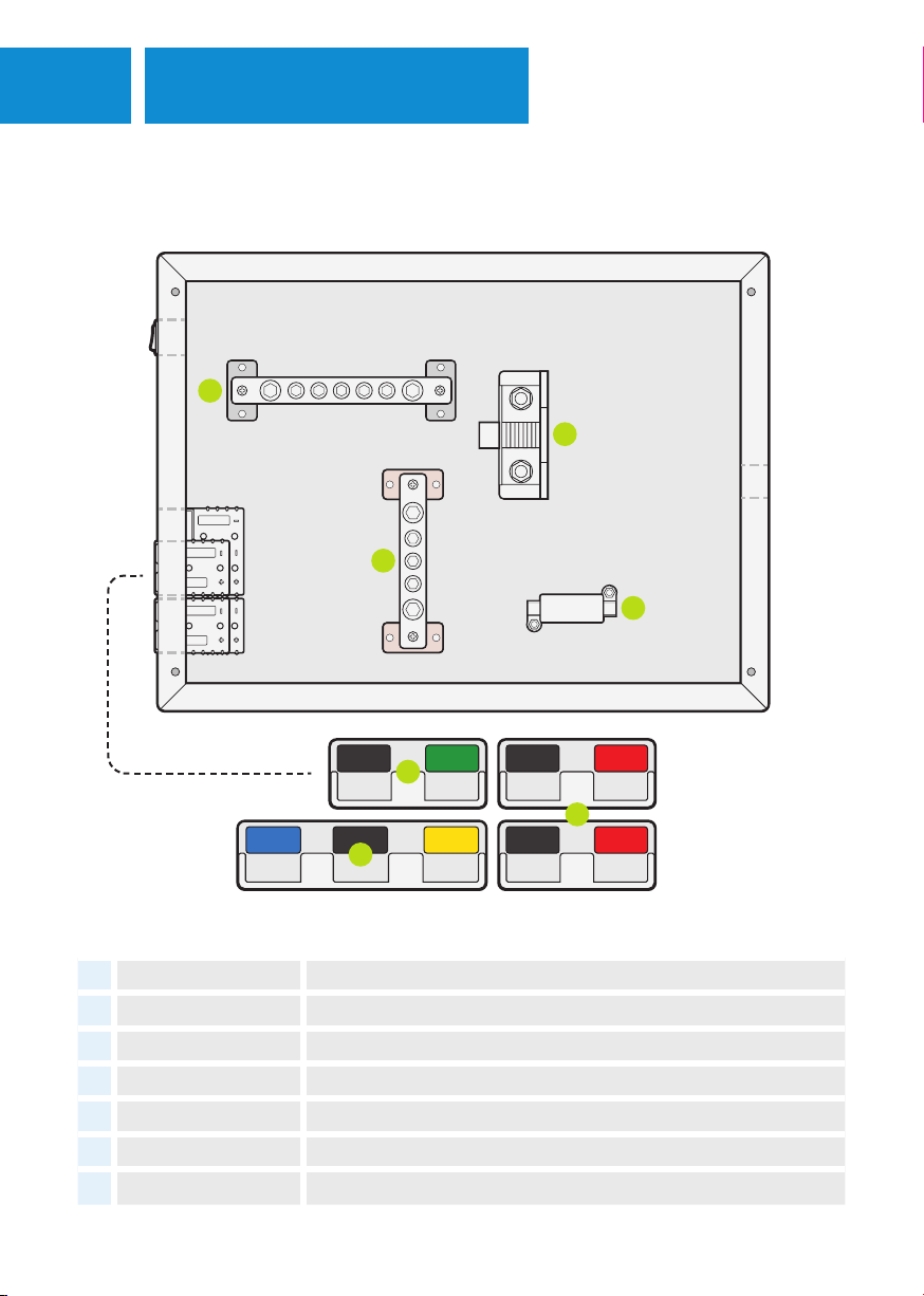
40A40A40A40A
CONTROL HUB INTERNAL OVERVIEW
# ITEM DESCRIPTION
12 500A shunt The apparatus that measures that battery's condition.
13 Positive busbar A distribution point used to manage all of the box's positive leads.
14 Negative busbar A distribution point used to manage all of the box's negative leads.
15 40A Midi-fuse Used as an over-load protection, dedicated to the DC-DC input.
16 Anderson output 30A Anderson-style plugs ideal for plugging in 12V appliances.
17 Solar input A dedicated solar input that connects to the DC-DC's MPPT regulator.
18 Alternator input A three-pin connection designed to connect the vehicle to the DC-DC unit.
14
12
15
13
17
18
16

6MOUNTING
CONTROL HUB INSTALLATION
Ideally suited to being mounted up on a 4x4 canopy wall, or in a camper trailer, the control hub is best
located in an area that’s easy to access and offers protection from dust and water ingress.
The unit should be mounted with consideration as to where/how you will be running your wires into/out
of the box. Make sure the box has adequate space around it to make wiring easy.
1. Using a Phillips head screwdriver, remove the
four screws found on each corner of the front
face of the unit.
2. Next, mark the mounting points on your wall/
surface. To do this, hold the box up to the
surface, and use a pen to mark the surface
through the box’s pre-drilled mounting holes.
PREPARATION
PROCESS
3. Then, put the control hub down and drill through each marking on your surface. To match the box’s
holes, you’ll need to create a 5mm hole. Note: If mounting to a metal surface, you may need to drill
a smaller pilot hole before drilling it out.
4. The box can now be lifted into place and secured to the wall. Thread an M5 bolt through each hole
and through the mounting surface, then fasten with suitable washers and nuts.
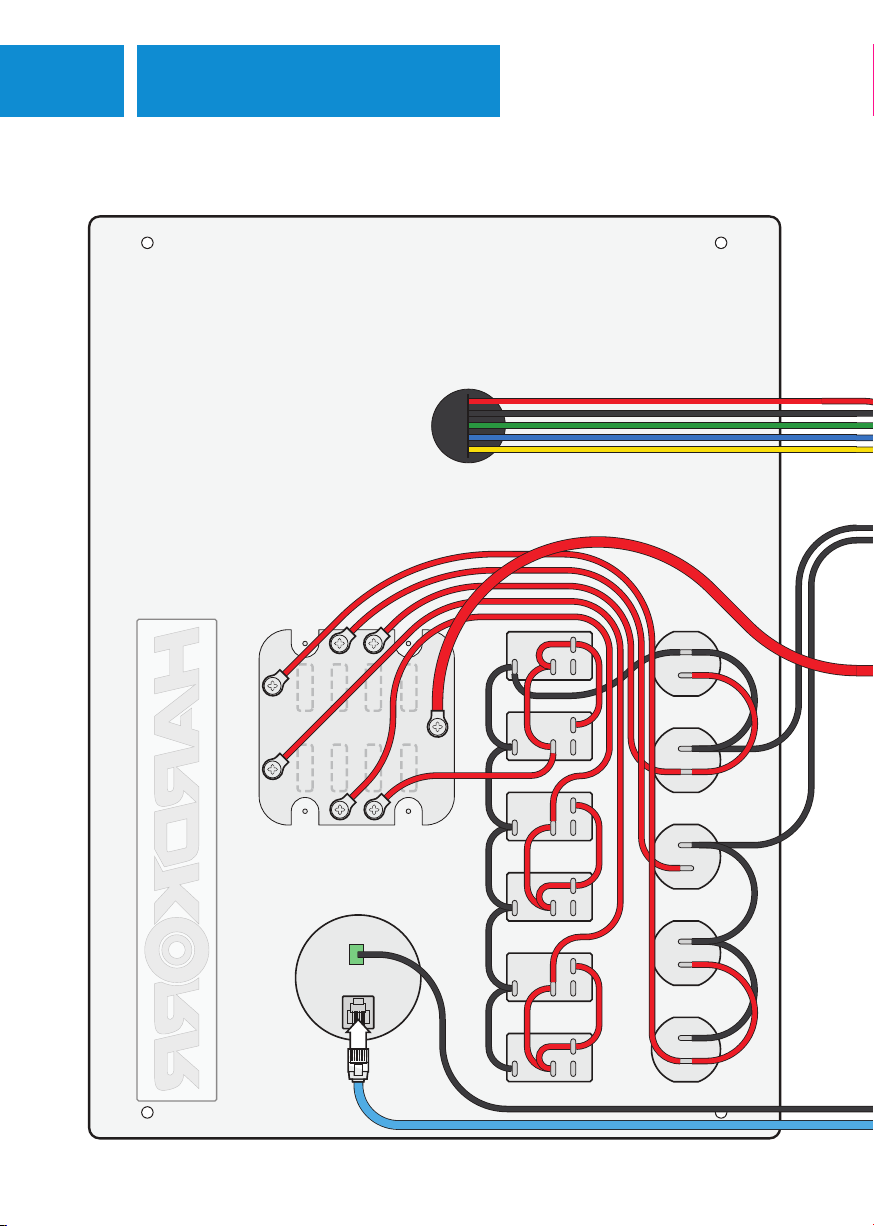
7WIRING DIAGRAM
LID INTERNAL WIRING DIAGRAM
40A40A
30A
30A
Wiring indicative only. Your hub may exhibit minor variations in connectivity.
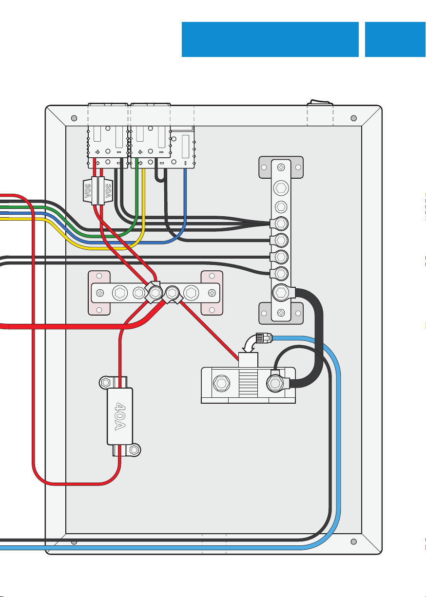
8WIRING DIAGRAM
CHASSIS INTERNAL WIRING DIAGRAM
40A40A
30A
30A
Wiring indicative only. Your hub may exhibit minor variations in connectivity.

9INSTALLATION
CONTROL HUB WIRING ACCESSORIES
• Disconnect the unit from power prior to wiring the switches.
• To wire into the switches, make sure your appliances are fitted with leads that are a minimum of
14AWG cable. Larger appliances may require cables at up to 10AWG.
• Each negative lead will require a 6mm ring terminal, whilst the positive requires a 6.3mm female
spade connector.
For wiring up any accessories that don't require a switch, simply wire the positive lead to the positive
busbar rather than the switch. The positive lead will need a 6mm ring terminal
WIRING ACCESSORIES WITHOUT A SWITCH
WIRING ACCESSORIES TO A SWITCH
1. Remove the front face of the unit by unscrewing the four screws found on each corner.
2. Locate a practical route for the wires to enter the hub from the appliance. Choose from one of
the four grommets on the unit, cut a cross through the centre of them, then run the cords from the
appliance into it so that there is about 30cm worth of lead in the box.
3. The positive lead can then be connected to the back of the switch. If your wiring is dual-core, you
may need to separate the two wires to do this, otherwise, place the female spade connector from
the positive lead onto the vacant male spade on your chosen switch.
4. Next, connect the negative eye terminal to one of the bolts on the negative busbar. Then repeat the
process for your other appliances, tucking the cables into the box once complete.
10INSTALLATION
CONTROL HUB WIRING INVERTER
• Consult your inverter’s user guide prior to installing through the hub.
• Take into consideration the appropriate cable gauge and fuse size needed to run your inverter. You
will need to use heavier gauge cables running from both the battery into the hub and from the hub
to the inverter.
• Some cables used will be too large to fit into the existing rubber grommets. You may need to modify
the box, drilling in larger holes to fit them.
• The positive and negative cables used to connect to the box should have 8mm eye terminals.
PROCESS
1. Remove the front face of the unit by unscrewing the four screws found on each corner.
2. Locate a practical route for the wires to enter the hub from the appliance. Run your leads from the
inverter into the box through one of the four grommets, or drill another hole if necessary.
3. There should be a vacant large bolt on the positive busbar. Secure the positive lead to this bolt.
4. Repeat the process above for the negative lead to the negative busbar.
40A40AFUSEFUSE
11 INSTALLATION
• Ensure that only a dedicated 12V battery/battery bank is used with the system.
• Make sure that the battery is of either SLA, AGM, Gel, Cal, or LiFePO4 chemistry.
• Inspect the unit internally to make sure that all the leads are in good working order and are of an
appropriate gauge.
• The kit does not come with any additional leads to wire the battery. Make sure to use leads that are
free from faults or frays and are of a suitable size being at least 6AWG. The leads used to connect
to the hub should have an 8mm eye terminal for the positive, and a 10mm eye terminal for the
negative as it will be attached to the shunt.
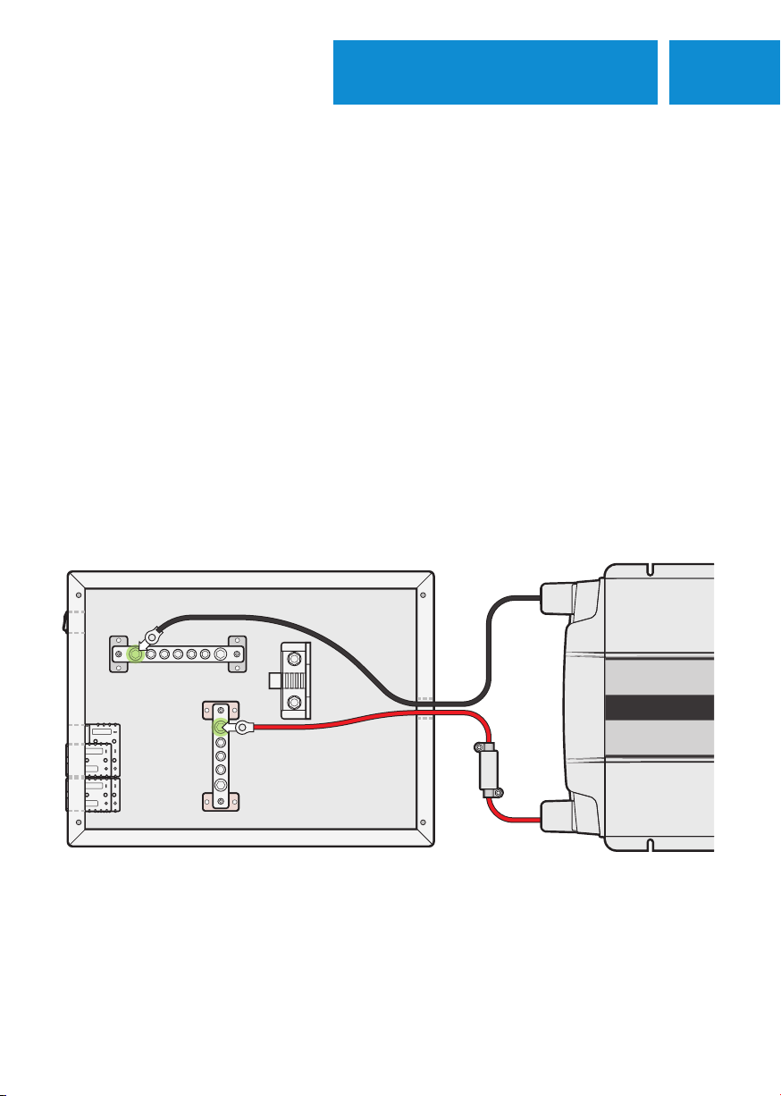
PROCESS
1. Remove the front face of the unit by unscrewing the four screws; one on each corner.
2. Locate the most practical route for the wires to run from the battery into the control hub. There are
grommets on all four sides giving you multiple options. Once located, cut a cross into the centre of
the rubber grommet using a knife.
3. Run your battery leads through the cut grommet so that there is about 30cm worth of lead in
the box. We recommend using a minimum of 6AWG cable, however, if the battery is located a
considerable distance from the box, you will need to use a larger gauge wire.
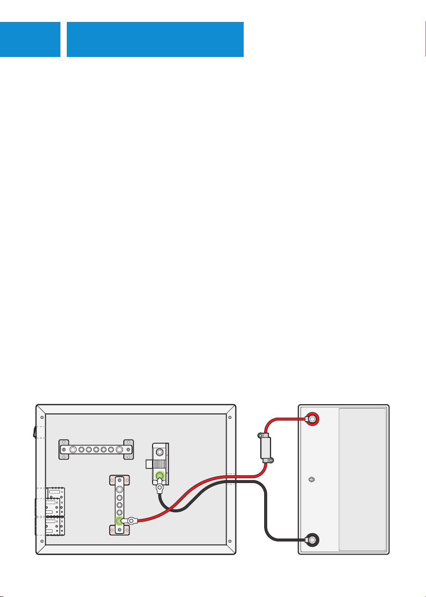
4. In the box, connect the terminal end from the positive lead to the main bolt on the positive busbar.
5. Next, connect the terminal end from the negative lead to the negative bolt on the shunt.
6. To complete this process, connect the cables to the battery. Connect the other end of the positive
cable first to the battery’s positive terminal, then connect the negative end to the battery’s negative
terminal.
CONTROL HUB WIRING AUXILLIARY BATTERY
BATTERY
40A40A
FUSEFUSE
12INSTALLATION
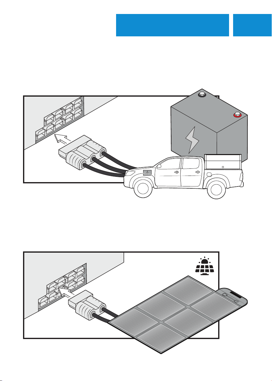
If you wish to use a separate solar regulator with your
solar setup, use one of the Anderson plug outputs instead.
The 12V Control Hub's DC-DC charger allows charging an auxilliary battery with the vehicle's alternator
using an Anderson 3-pole connector attached to your vehicle's battery and ignition source. For more
information, please consult the included DC-DC charger manual.
The 12V Control Hub's DC-DC charger allows charging an auxilliary battery with an input using an
Anderson 3-pole connector attached to your vehicle's battery and ignition source. For more information,
please consult the included DC-DC charger manual.
DCDC INPUT WIRING VEHICLE BATTERY
DCDC INPUT WIRING SOLAR
13 OPERATION
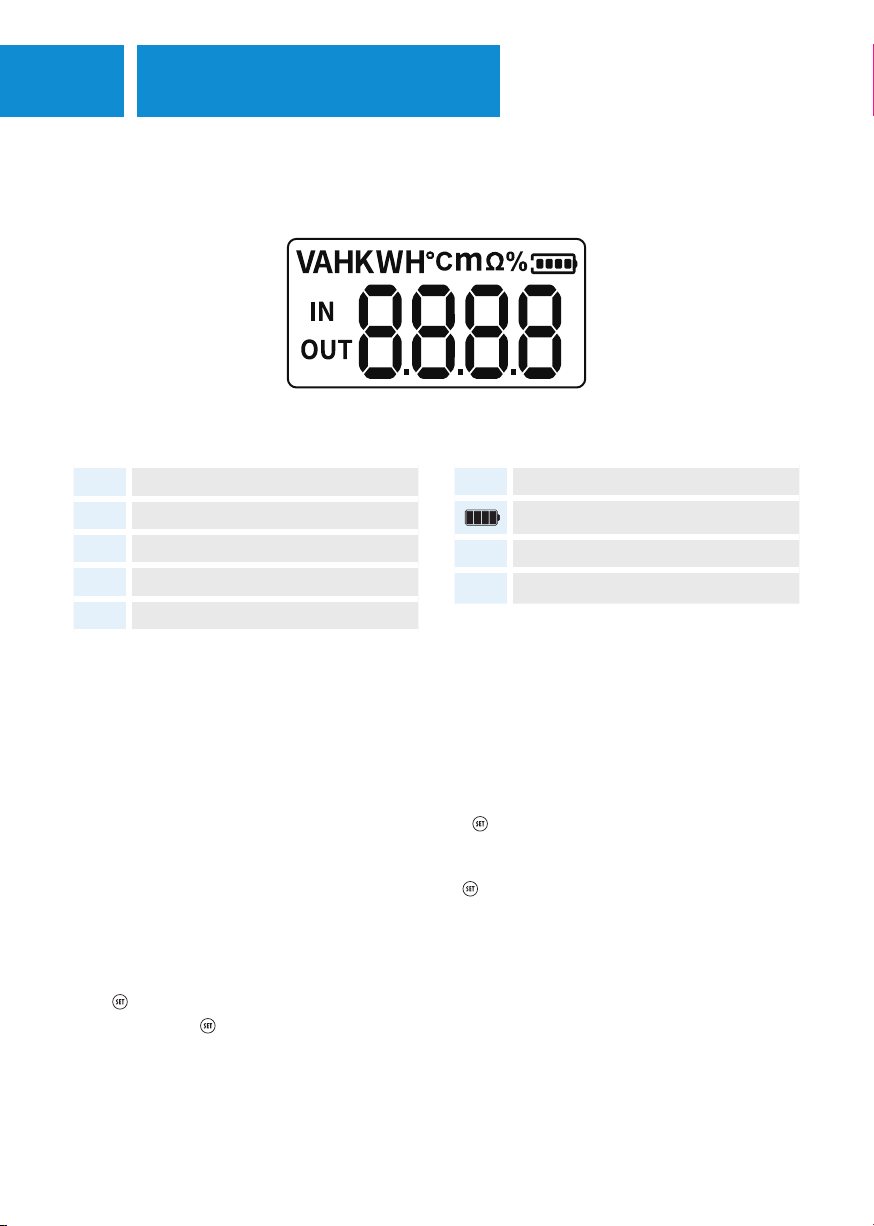
DISPLAY SWITCHING
Press <or >to switch between the display screens. The monitor’s default screen shows the battery voltage
(V), ranging from 8V~100V. Continuously pressing >, the battery current (A), power (W), amp-hours
(AH), temperature (°C), and capacity (%) will appear in order.
OVER/UNDER-VOLTAGE, OVER-CURRENT, OVER-TEMPERATURE, & AH CAPACITY SETTINGS
1. After switching to the corresponding interface, press for 2 seconds to enter the setting mode.
2. The setting value on the screen flashes 1second on and 1second off alternatively.
3. Use <or >to increase or decrease the value. Press to finish and exit.
BATTERY PERCENTAGE SETTING
The percentage displayed on the screen when using for the first time is not the accurate value of the
battery. Thus, it is suggested to reset the monitor’s capacity percentage. After the battery is fully charged,
Press for 2 seconds to enter the corresponding setting mode. Press >until percentage is displayed
100%. Then press to confirm and exit.
Make sure to set AH value at the first installation and that the , as the monitor will not do this
automatically. If set incorrectly, it will not give you an accurate reading. If you are charging and
discharging at the same time, the monitor shows the net amps. When the voltage is lower than setting
value, the battery capacity is automatically set as 0%.
BATTERY MONITOR
ICON FUNCTION / DESCRIPTION
VBattery voltage
ABattery current
WBattery power
AH Battery amp-hours
°C Battery temperature
%Capacity percentage
Battery state
IN Charging value
OUT Discharging value

14OPERATION
FAULT CODES
When over/under-voltage, over-current or
over-temperature occurs, the buzzer sounds 0.5
seconds on and 0.5 seconds off alternatively.
Press to mute the buzzer and return to the
normal status.
CODE FAULT
F1 Input over-voltage.
F2 Input under-voltage.
F3 Input over-current.
F4 Over-temperature.
The 12V control hub contains three cigarette sockets to allow you to plug in common appliances like
camp-fridges, inflation devices and lighting. The two left-most sockets are fused in tandem with a single
15A blade fuse. The right-most socket is fused on its own with a 15A blade fuse.
The 12Vcontrol hub contains an array of different types of USB ports for various uses like charging
phones and laptops, as well as using any small device that requires a USB connection. These are fused in
tandem with a single 15A blade fuse allowing for a maxumim combined current of 15A.
The 12V control hub contains two Anderson plug outputs. These are each fused with a 30A blade fuse.
The 12V control hub contains six rocker switches to provide direct switched control of your camp
accessories. These are fused with a 20A blade fuse in banks of two, allowing for a maximum combined
current of 20A between each pair of switches.
The 12V control hub contains an externally accessible fuse box housing the aforementioned blade fuses.
These are standard blade fuses and the bottom two fuses are spares that can be swapped out in the
event of a blown fuse. If you encounter a blown fuse, there is an indicator LED next to each socket that
will show you which needs replacing.
OUTPUT CIGARETTE SOCKETS
OUTPUT USB
OUTPUT ANDERSON
ROCKER SWITCHES
FUSE BOX

15 WARRANTY INFORMATION
TO BEGIN A WARRANTY CLAIM:
Our goods come with guarantees that cannot be excluded under the Australian Consumer Law. You
are entitled to a replacement or refund for a major failure and compensation for any other reasonably
foreseeable loss or damage. You are also entitled to have the goods repaired or replaced if the goods
fail to be of acceptable quality and the failure does not amount to a major failure.
Hardkorr warrants that this product will be free from defects in material and workmanship for two years.
The warranty commences on the date of purchase by the original purchaser, and is not transferable.
To access the benefits of this warranty, you must retain your proof of purchase and follow any other
direction we reasonably give you (e.g. completing and returning your warranty card if applicable).
If you believe your Hardkorr product is defective, it must be returned to Hardkorr for inspection by our
warranty claims department.
1. You must have a Return Authorization (RA) number. To get your RA number, please complete the
form found on our website and wait for the warranty team to contact you.
2. Once you have an RA number, you must arrange for the product must be shipped at your own
expense back to Hardkorr (keep your receipt). The address for shipment will be provided when we
issue your RA number.
3. Please be sure that your RA number is clearly marked on the outside of the packaging used for
shipping.
Completing the steps as mentioned will ensure a faster process of your claim, so that Hardkorr can get
your product back to you as soon as possible.
Once we receive your returned product, our technicians will inspect it. We will then notify you of the
outcome of your claim.
If we accept your warranty claim, we will either repair, replace or refund the goods at our discretion. We
will also reimburse you for the shipping costs you incurred in sending the goods back to us. Any products
that we choose to replace or refund become the property of Hardkorr.
If we do not accept your claim, we will advise you of the reason and hold your product for collection.
You will need to arrange and pay for the product to be shipped back to you. If your product is not
collected within 30 days of your warranty claim being finalised, we may destroy it.

DISCONTINUED ITEMS
Your warranty is voided if we (at our sole discretion) determine that there is evidence of one or more of
the following:
Negligence: Improper installation, improper or extreme use, use that contravenes this instruction
manual, etc.
Abuse: Road hazards, Damage beyond the limits of “normal wear and tear.”
Unauthorized Repair: Repair service performed by an unauthorised service centre.
Disassembly: Any attempt to open, tamper with or otherwise compromise the integrity of the product.
Consequential damage: damage to this product caused by the failure of another component of the
vehicle or device in which this product is installed.
Additionally, in the case of battery products: the following will void your warranty:
Incorrect charger: The use of a battery charger that is not suitable for lithium batteries i.e. does not
have a lithium battery charge profile.
Under bonnet use: Using this battery under the bonnet of a vehicle.
Overcharge/over-discharge: Charging or discharging your battery at a rate higher than those
stipulated in the Specifications table of this instruction manual.
Water ingress: your battery is not designed to be installed in an area that is subject to water ingress.
It is reasonable to expect that over its service life the capacity of your battery will reduce. Natural
capacity decrease, which we define as a decrease in capacity of less than 10% per year of ownership,
is not covered by this warranty. All batteries are tested using our in-house equipment and if we decline
your claim for capacity decrease we will provide you with a copy of the test report.
Exterior Finish: Hardkorr uses the highest quality materials available, but depending on location,
environment and exposure, the colour of exterior surfaces can fade. We will not approve any warranty
claims that relate to fade.
Discontinued items that are still under warranty will be reviewed by Hardkorr. If a discontinued item is
covered under warranty it may be replaced by an equivalent or superior item. If an equivalent item is not
available Hardkorr will determine terms of resolution on a case-by-case basis.

WWW.HARDKORR.COM
This manual suits for next models
1
Table of contents
Popular Switch manuals by other brands


Idem
Idem KLTM-RFID operating instructions

ATEN
ATEN Master View CS-1774 user manual

American Lighting
American Lighting SPEKTRUM Plus installation instructions

SMC Networks
SMC Networks 6900FSC - annexe 1 Management guide

Siemens
Siemens SIMATIC NET RUGGEDCOM RS900W installation manual

LevelOne
LevelOne GSW-0507 Quick installation guide