Harman Built Serenity II HB35 DV Installation instructions

1
R1
“Ce manuel est disponible en Français sur demande”

2
WARNING: If the information in this manual is not followed exactly, a re or explosion
may result causing property damage, personal injury or loss of life.
A. FOR YOUR SAFETY
Do not store or use gasoline or other ammable vapors and liquids in the vicinity of this or any other
appliance.
B. FOR YOUR SAFETY: WHAT TO DO IF YOU SMELL GAS
• Do not try to light any appliance.
• Open windows.
• Extinguish any open ame.
• Do not touch any electrical switch; do not use any phone in your building.
• Immediately call your gas supplier FROM A NEIGHBOR’S PHONE.
Follow the gas supplier’s instructions.
• If you cannot reach your gas supplier, call the re department.
C. Installation and service must be performed by a qualied gas installer, service agency, or the gas supplier.
Manufactured By:
Harman Stove Company
A Division Of Hearth & Home Technologies
352 Mountain House Road
Halifax, PA 17032

3
Table of Contents
Introduction 4
Safety Precautions 4
Operation 5
Specications 7
Installation 10
Arch Face 12
Venting 15
Fuel Conversion 26
Log Placement 28
Option Installation
Thermostat 29
Remote Control 29
Maintenance 30
Wiring Diagram 32
Parts 34
Trouble Shooting 36
Warranty 40

4Introduction
Due to high temperatures, the Serenity II Direct
Vent Gas Fireplace should be located out of trafc
and away from furniture and draperies.
Children and adults should be alerted to the
hazards of high surface temperatures and should
stay away to avoid burns or clothing ignition.
Young children should be carefully supervised
when they are in the same room as the appliance.
Clothing or other ammable materials should not
be placed on or near the appliance.
Surveiller les enfants. Garder les vetements, les
meubles, lessence ou autres liquides a vapeur
inammables lin de lappareil.
This appliance may be installed in an aftermarket
permanently located (mobile) home, where not
prohibited by local codes.
This appliance is only for use with the type(s) of
gas indicated on the rating plate. This appliance is
not convertible for use with other gases, unless a
certied kit is used.
Cet appareil peut etre installe dans un maison
prefabriquee (mobile) deja installee a demeure si
les reglements locaux le permettent.
Cet appareil doit etre utilise uniquement avec les
types de gas indiques sur la plaque signaletique.
Ne pas l utiliser avec d autres gas sauf si un kitde
conversion dertie est installe.
Any safety screen or guard removed for servicing
an appliance must be replaced prior to operating
the appliance.
When operating your Harman Serenity II Gas Fireplace,
respect basic safety standards. Read these instructions
carefully before you attempt to operate the replace.
Failure to do so may result in damage to property or
personal injury and may void the product warranty.
Consult with your local building code agency and
insurance representative before you begin your
installation to ensure compliance with local codes,
including the need for permits and follow-up inspections.
Several issues must be addressed when selecting a
suitable location for your Serenity II Gas Fireplace.
Observing required clearances to combustible materials,
the proximity to a safe venting system location, and
the accessibility of the gas and electrical supply must
all be considered. In addition, selecting a location that
takes advantage of the building’s natural air ow is also
desirable to maximize the heating effectiveness of the
replace. In many cases, this is a central location within
the building.
The Harman Serenity II Direct Vent Gas Fireplace is
a listed gas-red direct vent room replace tested by
Intertek Testing Services/Warnock Hersey to ANSI
Z21.88-2002/ CSA2.33-M02. CAN-CGA-2.17-M91.
The installation of the Serenity II Direct Vent Gas
Fireplace must conform with local codes, or in the
absence of local codes, with National Fuel Gas Code,
ANSI Z223.1 — latest edition and CAN 1 B1-149.1 and
.2 Installation Code.
Also for use in mobile (manufactured) homes after
home is sited.
Mobile (manufactured) home installations must adhere
to Title 24 CFR, part 3280, or CSA Z240.4.
CAUTION: This appliance must be vented to the
outside.
Installation and repair of the Serenity II Direct Vent
Gas Fireplace should be done by a qualied service
person. The appliance should be inspected before use
and at least annually by a qualied service person. More
frequent cleaning may be required due to excessive lint
from carpeting, bedding material, etc. It is imperative
that control compartments, burners, and circulating air
passageways of the Serenity II be kept clean.

OPERATION 5
Operation
HOW TO LIGHT THE FIRE
1. STOP! Read the safety information on page 2.
2. If using the optional thermostat, set thermostat to the
lowest setting.
3. Turn off electric power to the appliance.
4. Turn the ON-OFF/THERMOSTAT switch to the OFF
position.
5. Push in the gas control knob slightly and turn it
clockwise to “OFF.” NOTE: THE KNOB CANNOT
BE TURNED FROM “PILOT” TO “OFF” UNLESS
IT IS PUSHED IN SLIGHTLY. DO NOT FORCE IT.
6. Wait ve (5) minutes to clear out any gas. If you then
smell gas, STOP! Follow “B” in the safety information
inside the front cover. If you don’t smell gas, go to the
next step.
7. Set the High-Low Regulator to High by turning it
fully counterclockwise.
8. Press in the gas control knob slightly and turn
counterclockwise to “PILOT.”
9. Find the pilot by looking at the location shown in the
picture at lower left.
10. Push the control knob fully down and hold.
Immediately push the red piezo ignitor button to light
the pilot. It is normal to have to push the red button
several times before the pilot ignites. Continue to hold
the control knob in for about one minute after the pilot
is lit. Release the knob and it will pop back up. The Pilot
should remain lit. If it goes out, repeat steps 5 through 9.
•If the knob does not pop up when released, stop and
immediately call your service technician or gas supplier.
•If the pilot will not stay lit after several tries, turn
the gas control knob to “OFF” and call your service
technician or gas supplier.
11. Turn the gas control knob counterclockwise to “ON.”
12. Place the ON-OFF/THERMOSTAT switch in the
ON position or in the THERMOSTAT position if the
optional thermostat is used.
13. Turn on the electric power to the heater.
14. Set the optional thermostat to the desired room
temperature.
Gas Control
High-Low
ON-OFF/
THERMOSTAT
Switch
Blower Speed
Switch
Piezo Ignitor
Button
PILOT

OPERATION 6
15. Set the High-Low Regulator to desired setting: Turn
fully counterclockwise for High and fully clockwise
for Low.
NOTE: An odor, resulting from the initial heating of
new materials in your heater, is not unusual during the
rst re, and in most cases will disappear after an hour
or two.
HOW TO TURN OFF THE FIRE
1. If using optional thermostat, set thermostat to the
lowest position.
2. Turn off the electric power to the appliance.
3. Turn the ON-OFF/THERMOSTAT switch to the OFF
position.
4. Push in the gas control knob slightly and turn it
clockwise to “OFF.”
NOTE: The knob cannot be turned from “PILOT” to
“OFF” unless it is pushed in slightly. Do not force it.
FLAME HEIGHT ADJUSTMENT
The adjuster can be accessed by reaching to the left side
of the control panel and to the back of the unit. Turn
the adjuster counterclockwise (up) to increase ame
height and clockwise (down) to decrease. See above
left. Adjusting the ames too high will cause them to
have black tips and cause sooting. Sooting can cause
the glass to get dirty.
Warning: The unit and adjuster may be hot. Wear
gloves and arm protection if making adjustments
while in operation.
Pilot Flames
If pilot ames are less than shown at left, have your
service technician increase the ame height.
Flame Height
Adjuster
Bottom rear view of burner module.
Normal Flame pattern. Note: Flames will vary in height
and position depending on the placement and the amount of
ember wool.

7
SPECIFICATIONS
Accordion Heat
Exchanger Vent Collar
Brick
Hi-Low Knob
On-Off-Pilot Knob
Ignitor
Blower Speed Switch
On-Off- Thermostat
Switch
Burner Module
Electrical Box
Door Latches
Top Standoffs
Glass Door
Lift Handles
InputRating(Btu/hr)(0-4500ft.)(0-1375m) 31000 31000
Min.InputRating(Btu/hr)(0-4500ft.)(0-1375m) 21000 21000
Orices(DMS)(0-4500ft.)(0-1375m) 36 52
ManifoldPressure(inw.c./kPa) 3.5/.87 10.0/2.49
Min.ManifoldPressure(inw.c./kPa) 1.8/.45 5.6/1.4
Min.InletPressure(inw.c./kPa) 5.0/1.25 11.0/2.74
Max.Output(Btu/hr)(0-4500ft.)(0-1375m)(BlowerOff)24025 23637

8
SPECIFICATIONS
1
2
Optional Arch Hood
This replace may be placed on a wood oor.
Hearth is not required in
front of the replace
Electrical Rating: 120 Volts, 60 Hs, >2.75 AMP
MINIMUM CLEARANCES FROM COMBUSTIBLE CONSTRUCTION:
Unit to oor 0 in.
Face to side wall 7 in.
Unit to top stand-offs 0 in.
Unit to side stand-offs 0 in.
Unit to rear stand-offs 0 in.
Top of Glass to 8” Mantel 24in.
Venting to Combustibles 1 in. (Minimum Requirement, Check Venting Maunfacturer’s Guidelines.)
Must be
Noncombustible
2. Clearance from top of arch to bottom of wood facing 10 inches
1. Clearance from top of glass to 8” mantel 24 inches

9
SPECIFICATIONS
Right Side ViewLeft Side View
Top View
Gas In
Gas In
Electric In
41.943
36.879
16.374
15.374
Corner
Top View
56.42

10
INSTALLATION
Only For Qualied Installers
Wonder Board
Wood Mantel
Tile
Arch Face
Drywall
Typical Tile Facing Sectional View
Installation Options
This section deals with basic installation of an Arch
face. It does not describe every possible way to install
this replace. This is why it is important to have a
qualied installer do the installation.
The Serenity II can be laid in stone, brick, or other
masonry products. For this purpose, special face
templates ( part # 1-00-4235231 for arch faces and 1-00-
4235240 for rectangular faces ) are available.
We also offer a line of Harman Built mantels, mantel
cabinets, and corner mantel cabinets.
Shown is the M2 Mantel Cabinet with marble nish
facing, raised marble nish hearth and a gold
plated Arch face with Arch hood.

11
INSTALLATION
Only For Qualied Installers
Placement
Here are some of the things that will affect the exact
placement of the replace.
1. Venting conguration.
2. Arch, Rectangular or Victorian face. Arch and
Rectangular face - Must decide on mantel and front
facing material.
3. Raised hearth, at hearth or raised with no hearth.
5. Thermostat position.
6. Gas line hook-up is on the right side.
7. Electrical hook-up is on the left side.
This appliance must be electrically connected and
grounded in accordance with local codes or in the
absence of local codes, with the current edition of
NFPA 70-National Electric Code or CSA C22.1-
Canadian Electrical Code.
This unit shall not be installed on carpet, vinyl tile,
or combustible material other than wood.
42”
15¾”
37”

12
INSTALLATION
Only For Qualied Installers
Noncombustible
Noncombustible material such as Dura-rock must be used as
facing on the front of the replace cabinet.
Ceramic tile, marble or other decorative noncombustible
material may be used in front of the Dura-rock. The total
thickness for all layers of facing material may not exceed
one inch.
A one inch space under the front edge of the replace allows
room for hearth material. Hearth material that is thicker must
be compensated for by raising the replace the proper amount.
1 inch thick
Installing replace in a wall with an arch face, ceramic tile facing, and
a Harman Built (M1) Mantel.

13
INSTALLATION
Only For Qualied Installers
Latch Handles
Face Hooks
Slots for face hooks
Slots for face latches
Installing The Arch Face
To install the arch face, place the hooks on the
bottom rear of the face into the hook slots on the
replace. Next, with the top latch handles in the
horizontal position push the face against the replace
and swing the latches straight down causing them to
enter the top face slots.
Removing The Arch Face
To remove the face, unlatch the top latches, tilt the
top of the face away from the replace and lift the
face out of the bottom slots.
Rectangular Face
Rectangular faces are installed and removed the
same as arch faces.

14
INSTALLATION
Only For Qualied Installers
Burn Only the Fuel for which the Heater is
Equipped
The Serenity II Direct Vent will burn either natural gas
or propane, but requires a change over kit for propane.
The label on the burner system module indicates the fuel
for which it is equipped. A second label, (on the valve)
also indicates the fuel type.
Making The Connection
The gas inlet is located on the bottom right side of
the replace. The inlet tting is 1/2” male are tting
designed for 1/2” stainless ex pipe. This tting can be
removed to provide 3/8” female pipe thread.
A separate gas shut-off valve and a 1/8” N.P.T. plugged
tapping should be installed immediately upstream of the
connection to the appliance.
The Serenity II Direct Vent Gas Heater must be
disconnected from the gas supply piping during any
pressure testing of that system at pressures in excess of
1/2 psig (3.5 kPa).
The Serenity II gas control valve must be in the OFF
position during any pressure testing of the gas supply
system at pressures equal to or less than 1/2 psig (3.5
kPa).
WARNING: To avoid pipe compounds from entering
into the gas train, apply compounds only to male
pipe threads and do not apply compound to the rst
two threads.
CAUTION: TEST ALL JOINTS FOR LEAKS BEFORE
OPERATING.
Gas Pressure Requirements:
Correct gas pressure and the use of a properly sized
gas supply line are essential for the safe and efcient
performance of this appliance. Make sure that the
plumber or gas supplier checks the gas supply line and
gas pressure at installation.
NOTE: Improper gas pressure can affect heater
performance, ame color, or cause pilot outage.
Natural Gas:
Maximum inlet pressure 7.0” w.c. (1.74 kPa)
Minimum inlet pressure 5.0” w.c. (1.25 kPa)
Gas manifold pressure 3.5” w.c. (0.87 kPa)
Pipe Length Schedule 40 Pipe Tubing, Type L
(Feet) Inside Diameter Outside Diameter
N.G. L.P. N.G. L.P.
0-10 1/2” 3/8” 1/2” 3/8”
1.3 cm 1.0 cm 1.3 cm 1.0 cm
10-40 1/2” 1/2” 5/8” 1/2”
1.3 cm 1.3 cm 1.6 cm 1.3 cm
40-100 1/2” 1/2” 3/4” 1/2”
1.3 cm 1.3 cm 1.6 cm 1.3 cm
100-150 3/4” 1/2” 7/8” 3/4”
2.0 cm 1.3 cm 2.3 cm 2.0 cm
RECOMMENDED GAS PIPE DIAMETER
NOTE: NEVER USE PLASTIC PIPE. CHECK TO CON-
FIRM WHETHER YOUR LOCAL CODES ALLOW COPPER
TUBING OR GALVANIZED PIPE.
Use Only Approved Venting
This appliance has been tested and is listed for
installation with Simpson Duravent GS, Selkirk Direct
- Temp, Secure Vent Direct Vent, Montigo Direct Vent,
and ICC Excel Direct. The venting manufacturer’s
warranty will be voided, and serious re, health, or other
safety hazards may result from any of the following
actions:
• Installation of any damaged venting component.
• Unauthorized modication of any venting component.
• Installation of any mixed brand component(s).
• Installation other than as instructed by the venting
manufacturer and Harman Stove Company.
Consult your local building codes before beginning the
installation, and follow the manufacturer’s instructions
exactly. The following pages list the approved venting
components from each manufacturer.
LP Gas:
Maximum inlet pressure 13” w.c. (3.24 kPa)
Minimum inlet pressure 11” w.c. (2.74 kPa)
Gas manifold pressure 10” w.c. (2.49 kPa)
DO NOT USE THIS HEATER IF ANY PART
HAS BEEN UNDER WATER OR EXPOSED TO
MOISTURE CORROSION. IMMEDIATELY CALL A
QUALlFlED SERVICE TECHNICIAN TO INSPECT
THE HEATER AND REPLACE ANY PART OF THE
CONTROL SYSTEM AND ANY GAS CONTROL
WHICH HAS BEEN UNDER WATER.

VENTING
Only For Qualied Installers 15
Longueur6”Galvalume 6”LengthGalvalume TC-4DL6 TC-5DL6
Longueur6”Noire 6”LengthBlack TC-4DL6B TC-5DL6B
Longueur12”Galvalume 12”LengthGalvalume TC-4DL1 TC-5DL1
Longueur12”Noire 12”LengthBlack TC-4DL1B TC-5DL1B
Longueur24”Galvalume 24”LengthGalvalume TC-4DL2 TC-5DL2
Longueur24”Noire 24”LengthBlack TC-4DL2B TC-5DL2B
Longueur48”Galvalume 48”LengthGalvalume TC-4DL4 TC-5DL4
Longueur48”Noire 48”LengthBlack TC-4DL4B TC-5DL4B
LongueurFlexible36” FlexibleLength36” TC-4DLF TC-5DLF
LongueurTélescopique12”Galvalume 12”AdjustableLengthGalvalume TC-4DLT TC-5DLT
LongueurTélescopique12”Noire 12”AdjustableLengthBlack TC-4DLTB TC-5DLTB
Coude45°Galvalume 45°ElbowGalvalume TE-4DE45 TE-5DE45
Coude45°Noire 45°ElbowBlack TE-4DE45B TE-5DE45B
Coude90°Galvalume 90°ElbowGalvalume TE-4DE90 TE-5DE90
Coude90°Black 90°ElbowBlack TE-4DE90B TE-5DE90B
Supportcarré/Coupe-feuradiant* SquareSupport/RadiationShield* TM-4SS TM-5SS
Supportrond/Coupe-feuradiant** RoundSupport/RadiationShield** TM-4RDS TM-5RDS
Supportpourplafond/Coupe-feu CeilingSupport/Firestop TM-4CS TM-5CS
Supportdedéviation OffsetSupport TM-OS
Supportdetoit RoofSupport TM-SR
Supportmuralajustable AdjustableWallSupport TM-WS
Coupe-feumuralajustable AdjustableWallThimble TM-4WT TM-5WT
Anneaudenitionnoire TrimRingBlack TM-4TR TM-5TR
Coupe-feuradiantd’entretoit AtticRadiationShield/Firestop TM-4AS TM-5AS
Chapeauhorizontal HorizontalTermination TM-4HT TM-5HT
Chapeauhorizontaldeluxe DeluxeHorizontalTermination TM-4DHT TM-5DHT
Chapeauvertical VerticalTermination TM-4VT TM-5VT
Chapeaupériscope14” 14”SnorkelTermination TM-4ST14 TM-5ST14
Chapeaupériscope36” 36”SnorkelTermination TM-4ST36 TM-5ST36
Solinplat FlatFlashing TF-4F XF-6EF
Solinajustable1/12-7/12 AdjustableFlashing1/12-7/12 TF-4FA XF-6EFA
Solinajustable8/12-12/12 AdjustableFlashing8/12-12/12 TF-4FB XF-6EFB
Solinpourcheminéedemaçonnerie MasonryChimneyFlashing TF-4MF ---
Colletdesolin StormCollar TM-SC
Disquerestricteur RestrictorDisc TM-4RD
Protecteurdevinyl VinylSidingStandoff TM-VSS
Adaptateurpourappareildecoaxialàcolinéaire CoaxialtoCollinearApplianceAdaptor TM-4CAA
Adaptateurpourchapeaudecolinéaireàcoaxial CollineartoCoaxialTerminationAdaptor TM-4CTA
Raccorddegaineexible3” FlexLinerConnector3” TM-CFAA3
Adaptateurdecheminée6”-TypeAetmaçonnerie*** TypeA/MasonryChimneyAdaptor6”*** TM-4CA6 ---
Adaptateurdecheminée7”-TypeA*** TypeAChimneyAdaptor-7”*** TM-4CA7 ---
Adaptateurdecheminée8”-TypeA*** TypeAChimneyAdaptor-8”*** TM-4CA8 ---
EXCELDirect Component List
* Order the Excel chimney square support extension (6ESSE for 4” , and 7ESSE for 5”) if required.
** Order the Excel chimney round support extension (6ERDSE for 4”, and 7ERDSE for 5”) if required.
*** These Components are not UL or Warnock Hersey listed.

VENTING
Only For Qualied Installers 16
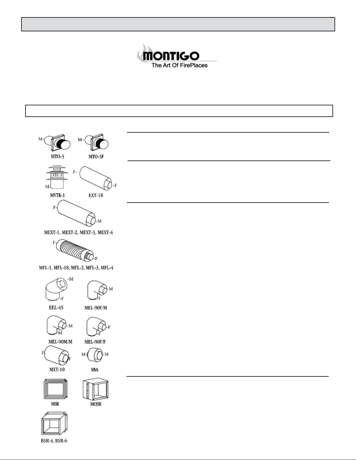
908 6”PipeLength,Galvanized
908B 6”PipeLength,Black
907 9”PipeLength,Galvanized
907B 9”PipeLength,Black
906 12”PipeLength,Galvanized
906B 12”PipeLength,Black
n/a
n/a
904 24”PipeLength,Galvanized
904B 24”PipeLength,Black
903 36”PipeLength,Galvanized
903B 36”PipeLength,Black
902 48”PipeLength,Galvanized
902B 48”PipeLength,Black
911 AdjustableLength,11”-14”,Galv.
911B AdjustableLength,11”-14”,Black
945 45oElbow,Galvanized
945B 45oElbow,Black
990 90oElbow,Galvanized
90B 90oElbow,Black
n/a
929 RestrictorDisc
949 RoundCeilingSpt/WallThimbleCvr
941 CathedralCeilingSupportBox
988 WallStrap
989 ElbowStrap
942 WallThimble
963 CeilingFirestop
n/a
970 BasicHorizontalTerm.Kit
971 HorizontalTerminationKitA
978 VerticalTerminationKit
991 HighWindTerminationCap
985 HorizontalSquareHighWindTermination
953 StormCollar
943 AdjustableFlashing,0/12-6/12
943S AdjustableFlashing6/12-12/12
950 VinylSidingStandoff
n/a
982 SnorkelTerminationCap14”
981 SnorkelTerminationCap36”
4DT-6 6”PipeLength,Galvanized
4DT-6B 6”PipeLength,Black
4DT-9 9”PipeLength,Galvanized
4DT-9B 9”PipeLength,Black
4DT-12 12”PipeLength,Galvanized
4DT-12B 12”PipeLength,Black
4DT-18 18”PipeLength,Galvanized
4DT-18B 18”PipeLength,Black
4DT-24 24”PipeLength,Galvanized
4DT-24B 24”PipeLength,Black
4DT-36 36”PipeLength,Galvanized
4DT-36B 36”PipeLength,Black
4DT-48 48”PipeLength,Galvanized
4DT-48B 48”PipeLength,Black
4DT-AJ AdjustableLength,11”-14”,Galv.
4DT-AJB AdjustableLength,11”-14”,Black
4DT-EL45 45oElbow,Galvanized
4DT-EL45B 45oElbow,Black
4DT-EL90 90oElbow,Galvanized
4DT-EL90B 90oElbow,Black
4DT-AA ApplianceAdaptor,Black
4DT-RD RestrictionDisc
4DT-CS CeilingSupport
4DT-CSS CathedralSupportBox
4DT-WS/B WallSupportBand
4DT-OS OffsetSupport
4DT-WT RoundWallThimble,Black
4DT-FS FirestopSpacer
4DT-TP TrimPlate,Black
4DT-HKA HorizontalTerm.KitA
4DT-HKB HorizontalTerm.KitB
4DT-VKC VerticalTerminationKit
4DT-HVC HighWindVerticalCap
4DT-HHC HighWindHorizontalCap
4DT-SC StormCollar
4DT-AF6 AdjustableFlashing,0/12-6/12
4DT-AF12 AdjustableFlashing6/12-12/12
4DT-VS VinylSidingStandoff
4DT-VSP VinylSidingShieldPlate
4DT-ST14 SnorkelTermination14”
4DT-ST36 SnorkelTermination36”

VENTING
Only For Qualied Installers 17
Length6”(Galvalume) SV4L6 908 SV5L6 1208
Length6”(Black) SV4LB6 908B SV5LB6 1208B
Length12”(Galvalume) SV4L12 906 SV5L12 1206
Length12”(Black) SV4LB12 906B SV5LB12 1206B
Length24”(Galvalume) SV4L24 904 SV5L24 1204
Length24”(Black) SV4LB24 904B SV5LB24 1204B
Length36”(Galvalume) SV4L36 903 SV5L36 1203
Length36”(Black) SV4LB36 903B SV5LB36 1203B
Length48”(Galvalume) SV4L48 902 SV5L48 1202
Length48”(Black) SV4LB48 902B SV5LB48 1202B
Adj.Length(Galv.)(Adjustable6”) SV4LA n/a SV5LA n/a
Adj.Length(Blk)(Adjustable6”) SV4LBA n/a SV5LBA n/a
Adj.Length(Galv.)(Adjustable12”) SV4LA12 n/a SV5LA12 n/a
Adj.Length(Blk)(Adjustable12”) SV4LBA12 n/a SV5LBA12 n/a
Adj.Length(Galv.)(Adjustable24”) SV4LA24 917 SV5LA24 1217
Adj.Length(Blk)(Adjustable24”) SV4LBA24 917B SV5LBA24 1217B
Swivel45oelbow(Galvalume) SV4E45 945G SV5E45 1245G
Swivel45oelbow(Black) SV4EB45 945BG SV5EB45 1245BG
Rigid45oelbow(Black) SV4EBR45 945B SV5EBR45 1245B
Swivel90oelbow(Galvalume) SV4E90 990G SV5E90 1290G
Swivel90oelbow(Black) SV4EB90 990BG SV5EB90 1290BG
Rigid90oelbow(Black) SV4EBR90 990B SV5EBR90 1290B
AdjustableDecorative
SquareCathedralSupport SV4CSB 941 SV5CSB 1241
CollarfortheDecorative
SquareCathedralSupport SV4AC n/a SV5AC n/a
DecorativeBlackPlate(square) SV4PF 940 SV5PF 1240
UniversalSupport SV4SU 989 SV5SU 1289
FloorSupport SV4SD n/a SV5SD n/a
RoofBrace SV4BS n/a SV5BS n/a
RoofSupport SV4ST n/a SV5ST n/a
WallBand SV4BM 988 SV5BM 1288
AtticRadiationShield SV4RSA n/a SV5RSA n/a
WallRadiationShield SV4RSM 942 SV5RSM 1242
Firestop SV4BF 963 SV5BF 1263
FlatRoofFlashing(stormcollarincl.) SV4F 943F SV5F 1243F
AdjustableRoofFlashing
1/12-7/12(stormcollarincl.) SV4FA 943 SV5FA 1243
AdjustableRoofFlashing
8/12-12/12(stormcollarincl.) SV4FB 943S SV5F B 1243S
StormCollar SV4FC 953 SV5FC 1253
VinylShieldProtector SV4VS 950 SV5VS 1250
RestrictorDisk SV4RD 929 SV5RD n/a
VERTICALTERMINATIONCAP SV4CGV 980 SV5CGV 1280
HORIZONTALTERMINATIONCAP SV4CHC-1 984 SV5CHC-1 1284
SNORKELCAP14” SV4STC14 982 SV5STC14 1282
SNORKELCAP36” SV4STC36 981 SV5STC36 1281

VENTING
Only For Qualied Installers 18
3”length,nomountingframe(usewithMSRorMOSR) MTO3
3”Termination,withintegralmountingframe MTO3F
Terminationforverticalinstallations MVTK1
IncludesMXT-10adaptor(forstraight,verticalinstallations)
TerminationTouch-UpPaint Paint03
18”rigidsection(female/female) EXT18
12”rigidsection(female/male) MEXT1
24”rigidsection(female/male) MEXT2
36”rigidsection(female/male) MEXT3
48”rigidsection(female/male) MEXT4
72”rigidsection(female/male) MEXT6
12”exsection(female/femaleconnectors) MFL1
18”exsection(female/female) MFL18
24”exsection(female/female) MFL2
36”exsection(female/female) MFL3
48”exsection(female/female) MFL4
45°solidelbowsection(female/maleconnectors) EEL45
90°elbow(female/female) MEL90F/F
90°elbow(male/male) MEL90M/M
90°elbow(female/male) MEL90F/M
ClearanceReducingSleeve CRS30
10”ueadaptorforstraight,verticalinstallations(female/female) MXT10
4”ventconnector(male/male) MVA
MSR
Usedforeasyinstallationoftermination.
MOSR
Usedtoprovideinstallationofterminationfromtheinsideofthebuilding.
Usedforinstallationofterminationonbrickwall.
4”depth BSR-4
6”depth BSR-6

VENTING
Only For Qualied Installers 19
18”verticalrise SNK47-2
30”verticalrise SNK47-3
FitsallStandardSeries(4/7”)terminations MTKOG
for4”/7”venting RHS100
Recommendedforprotectingvinylsiding RHS105
Replacewith
Recommendedforprotectingvinylsiding VSS
7”Firestop FS7
7”Supportplate&supportring MSPXT7
7”Supportplate&supportring(Bulkpackof6) MSP706
Flashingandstormcollarfor1/12to7/12pitchroof MRF7
Flashingandstormcollarfor1/12to7/12pitchroof(Bulkpackof6) MRF706
Flashingandstormcollarfor7/12to12/12pitchroof MRF-12
Flashingandstormcollarfor7/12to12/12pitchroof(Bulkpackof6) MRF1206
For8’-14’horizontalventrun MHVR8
For15’-24”horizontalventrun MHVR15
For25’-35’horitontalventrun MHVR25
Ventrestrictorsmaynotberequired.Contactthefactoryformoreinformation.
For8’-14’verticalventrun MVVR8
For15’-24”verticalventrun MVVR15
For25’orgreaterverticalventrun MVVR25
Ventrestrictorsmaynotberequired.Contactthefactoryformoreinformation.
WallPenetrationKit(ForConstruction) WPKMH4
Kitincludeswallshieldand4”termination.Suitableforall
cornerinstallations&straightthroughthewallinstallations
with2x4construction.
WallPenetrationKit(ForConstruction) WPKMH6
Kitincludeswallshieldand5”termination.

VENTING
Only For Qualied Installers 20
3”Terminationwithnomountingframe(maleconnector) PTO3
(usewithMSRorMOSR).
3”Termination&mountingframe(maleconnector) PTO3F
Terminationforverticalinstallations(maleconnector) PVTK1
IncludesPXT-10adaptor(forstraight,verticalinstallations).
ForallRearVentapplicationswithnoverticalrise,thereisamaximum
horizontalrunof20”.
5”rigidsection(female/femaleconnectors) PXT5
10”rigidsection(female/female) PXT10
20”rigidsection(female/female) PXT20
12”rigidsection(female/maleconnectors) PEXT1
24”rigidsection(female/male) PEXT2
36”rigidsection(female/male) PEXT3
48”rigidsection(female/male) PEXT4
72”rigidsection(female/male) PEXT6
12”exsection(female/femaleconnectors) PFL1
18”exsection(female/female) PFL18
24”exsection(female/female) PFL2
36”exsection(female/female) PFL3
48”exsection(female/female) PFL4
45°elbow(female/maleconnectors) PEL45FM
90°elbow(female/femaleconnectors) PEL90F/F
90°elbow(male/male) PEL90M/M
90°elbow(female/male) PEL90F/M
ClearanceReducingSleeve CRS30
4”lengthventconnector(male/maleconnectors) PVA
10”length,reducesvertical5”/8”ventingto4”/7”(male/femaleconnectors)PVA5487
MSR
Usedforeasyinstallationoftermination.
MOSR
Usedtoprovideinstallationofterminationfromtheinsideofthebuilding.
Usedforinstallationofterminationonbrickwall.
4”depth BSR-4
6”depth BSR-6
Table of contents
Popular Indoor Fireplace manuals by other brands

Pur Line
Pur Line Biochimenea Hypnos installation instructions

Heat & Glo
Heat & Glo FDN-5-PIER Installation and operating manual

Heat & Glo
Heat & Glo Cyclone-Cust owner's manual

Quality Craft
Quality Craft M850P-26FDC instruction manual

RealFlame
RealFlame 11564LP1 owner's manual

Procom
Procom BN28TYLA-W OWNER'S OPERATION AND INSTALLATION MANUAL