~~I
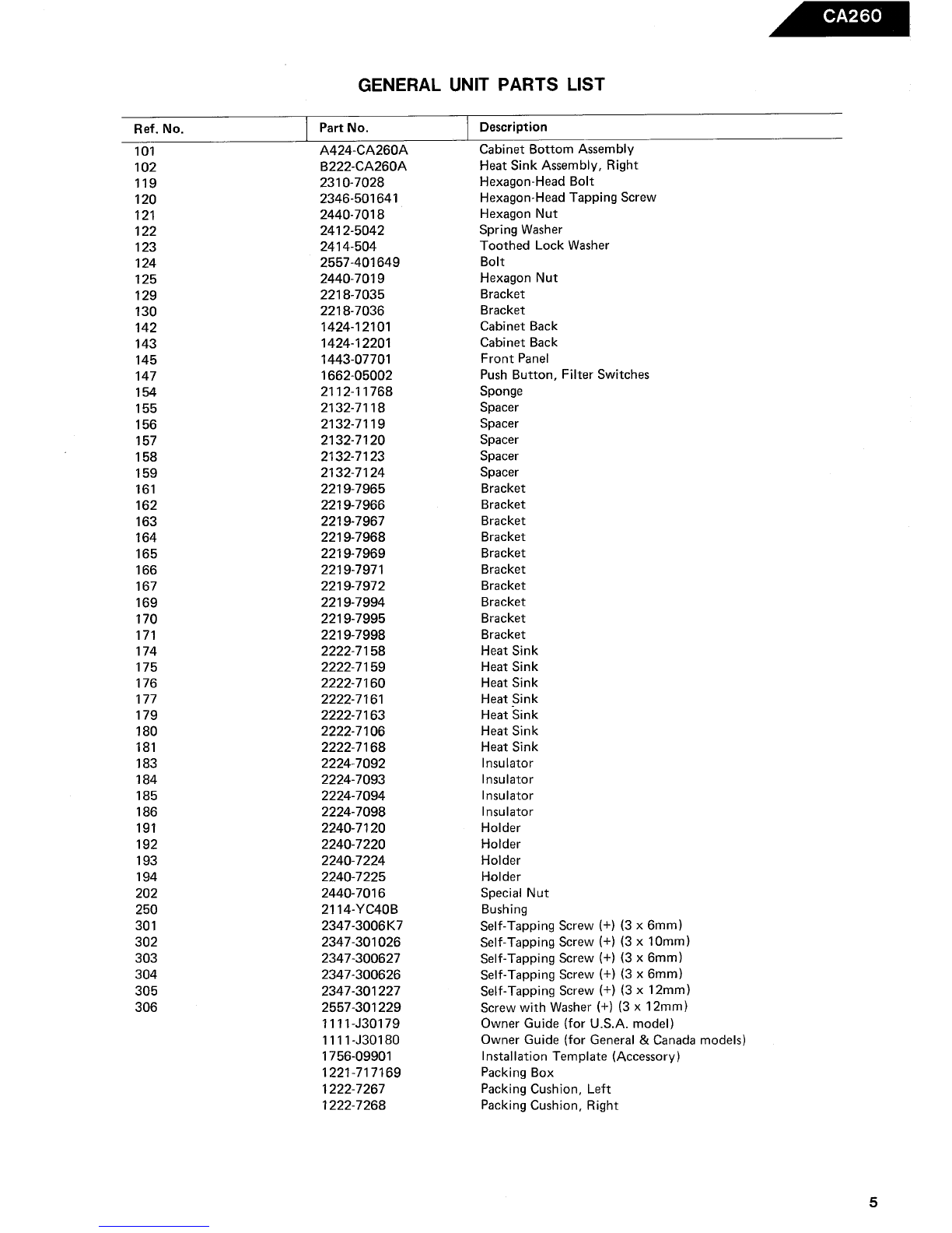
Power Output, RMS : 60 watts per channel into
4 Ohms, 20 ~ 20,000Hz
: 90 watts per channel into
2 Ohms, 20 ~ 20,000Hz
: 180 watts bridged mono into
4 Ohms, 20 ~ 20,000Hz
HCC (High Instantaneous: :t 30A
Current Capability)
THD
Negative Feedback
Power Bandwidth
Frequency Response
Signal-to-Noise Ratio
I nput Sensitivity
Line Level
High Level
: No more than 0.
: 25dB
: 10Hz to 100 000Hz
: 10Hz to 100,000Hz
: 80dB + 0
, -
3dB
: 0. 25V 10.8V (switchable)
: 3V
Active Crossover Characteristics
High Pass : 200Hz, 12d B/Octave
Low Pass : 200Hz, 6dB/Octave
Power Supply : DC + 13.8V (11 ~ 16V usable),
negative ground
Typical Input Current Requirements
At Idle : 2.
Full Power Music Signal: 6.7 A (4 Ohms/ch.
: lOA (2 Ohms/ch.
Full Power Sine Wave : 20A (4 Ohms/ch.
: 30A (2 Ohms/ch.
Dimensions (W x H x D) : 15-5/8"x3-7/8"x7-1/8"
(396 x 98 x 180 mm)
: 101bs. 20z (4.6kg)
Weight
All specifications and features subject to change without notice.
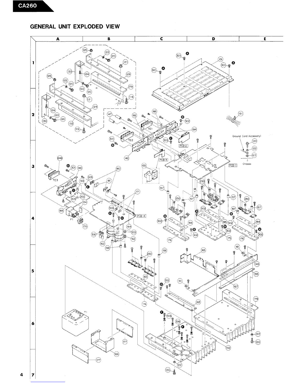
DISASSEMBLY PROCEDURES (REFER TO PAGES 4 AND 10)
Note: When replacing parts, discharge by shorting between
terminals of the capacitor (C51 , C52) at the power
source with 8D 1O0W resistor as it may have
charge accumulated.
IIJ CABINET BOTTOM ASSEMBLY (101) REMOVAL
Remove 7 screws ~ and remove the Cabinet Bottom
Assembly (101).
IZJ MAIN P.C. BOARD (PCB-1) REMOVAL
1. Remove the Cabinet Bottom Assembly (101). (Refer
to step rn .
2. Remove 9 screws fY and remove the Main P C. Board
(PCB-l) with Cabinet Back (142), Line Input P
Board (PCB-2), Bridged-Mono Switch P C. Board
(PCB-3) and terminals (TEl and TE2).
3. Unsolder the lead wires from the Line Input P
Board (PCB-2) and Bridged- Mono Switch P.C. Board
(PCB-3) and remove the terminals (TEl and TE2)
by unsoldering.
4. Remove 2 screws ~ and remove the Cabinet Back
(142) with the Line Input P C. Board (PCB- 2),
Bridged-Mono Switch P C. Board (PCB-3) and ter-
minals (TEl and TE2).
PROTECTION CIRCUIT
If the temperature inside the CA260 rises above 80
the protection circuit comes into operation, decreasing
output. At this time the protect indicator blinks. If the
temperature comes back below 80 C by natural cooling,
output returns as it was.
If the temperature rises above 100 , the power supply
circuit is shut off. Not only does the output stop, but
also the protect indicator goes out. If this happens, it
is possible that the CA260 is broken. However, even in
this state, it cannot be always said that it is broken
because the unit may operate when the temperature
comes back below 80 C by natural cooling.
~ POWER SUPPLY P.C. BOARD (PCB-4) REMOVAL
1. Remove the Cabinet Bottom Assembly (101). (Refer
to step rn .
2. Unsolder the lead wires from the Power Transformer
(Tl ).
3. Remove 7 screws C!) and remove the Power Supply
C. Board (PCB-4) with the Cabinet Back (143),
Fuse with Holder (Fl), Insulator (186) and terminal
(TE3).
4. Remove the terminal (TE3) by unsoldering.
5. Remove screw C) and remove the Cabinet Back
(143) with Fuse with Holder (Fl), Insulator (186)
and terminal (TE3). At this time, disconnect the
connector from Fuse with Holder (F 1).
141 POWER TRANSFORMER (T1) REMOVAL
1. Remove the Power Supply P C. Board (PCB-4).
(Refer to step
~ .
2. Remove 4 screws () and remove the Power Trans-
former (T1).
ToSw;tch;ng 03
:"' --Q --,0,----..2
_138V PROTECT
D W i--
I ~'
~;;
'" Jr~l
'~i...