manuals.online logo
Brands
  1. Home
  2. •
  3. Brands
  4. •
  5. Harman Kardon
  6. •
  7. Receiver
  8. •
  9. Harman Kardon AVR20 II User manual

Harman Kardon AVR20 II User manual

=
eee
3
4
kooNoomoomaes
3a
q
Beane
33
ee
FAN
CHAT
fas
oxsomconconore
Eres
osennarnonesinen
soon)
st
oe
es
harman/kardon.
Audio
and
Video
Receiver
OWNER'S
MANUAL
CAUTION
RISK
OF
ELECTRIC
SHOCK
DO
NOT
OPEN
CAUTION:
TO
REDUCE
THE
RISK
OF
ELECTRIC
SHOCK,
DO
NOT
REMOVE
COVER
(OR
BACK).
NO
USER-SERVICEABLE
PARTS
INSIDE.
REFER
SERVICING
TO
QUALIFIED
SERVICE
PERSONNEL.
The
lightning
flash
with
arrowhead
The
exclamation
point
within
an
symbol,
within
an
equilateral
triangle,
is
equilateral
triangle
is
intended
to
alert
the
intended
to
alert
the
user
to
the
presence
user
to
the
presence
of
important
.
of
uninsulated
"dangerous
voltage”
within
operating
and
maintenance
(servicing)
the
produci’s
enclosure
that
may
be
of
;
instructions
in
the
literature
accompanying
sufficient
magnitude
to
constitute
a
risk
of
the
appliance.
electric
shock
to
persons.
WARNING:
TO
REDUCE
THE
RISK
OF
FIRE
OR
ELECTRIC
SHOCK,
DO
NOT
EXPOSE
THIS
APPLIANCE
TO
RAIN
OR
MOISTURE.
7
CAUTION:
TO
PREVENT
ELECTRIC
SHOCK,
MATCH
WIDE
BLADE
OF
PLUG
TO
WIDE
SLOT,
FULLY
INSERT.
ATTENTION:
POUR
EVITER
LES
CHOCS
ELECTRIQUES,
INTRODUIRE
LA
LAME
LA
PLUS
LARGE
DE
LA
FICHE
DANS
LA
BORNE
CORRESPONDANTE
DE
LA
PRISE
ET
POUSSER
JUSQU’AU
FOND.
Harman
Kardon
AVR20
Il
Date
of
purchase
Purchased
from
Address
of
business
purchased
from
Installed
by
Date
installed
Serial
No.
Note
to
CATV
System
installer:
This
reminder
is
provided
to
call
the
CATV
system
installer’s
attention
to
Article
820-40
of
the
NEC
that
provides
guidelines
for
proper
grounding
and,
in
particular,
specifies
that
the
cable
ground
shall
be
connected
to
the
grounding
system
of
the
building,
as
close
to
the
point
of
cable
entry
as
practical.
|
“Thank
you
for
choosing
a
Harman
Kardon
Audio/Video
Receiver.
Your
new
unit
is
an
exceptionally
well-engineered
product
that
will
give
you
years
of
superb
performance.
Save
all
packing
material.
It
is
essential
for
shipping
should
you
move,
or
in
the
event
the
unit
ever
needs
repair.
U.
S.
and
Canadian
customers
should
uge 120
volt
AC
only.
Other
customers
should
use
voltages
appropriate
to
their
area.
Connecting
the
unit
to
an
outlet
supplying
a
higher
voltage
may
create
a
fire
hazard.
Handle
the
Power
Cord
Gently.
M
To
disconnect
the
plug
from
the
AC
outlet,
pull
on
the
plug
itself,
not
on
the
cord.
Hi
Disconnect
the
plug
from
the
AC
outlet
whenever
the
unit
is
to
be
left
unused
for
an
extended
period
of
time.
HM
Do
not
place
furniture
or
other.
heavy
objects
on
the
cord,
and
avoid
dropping
heavy
objects
on
it.
Also
do
not
make
a
knot
in
the
cord.
Piace
the
unit
on
a
firm
and
level
surface.
Avoid
installing
it:
M@
In
moist
or
humid
places;
HM
Close
to
heating
equipment
or
in
places
exposed
to.
direct
sunlight;
M@
ina
direct
draft
from
an
air
conditioner
or
in
other
very
cold
locations;
M@
in
places
subject
to
excessive
vibration
or
dust;
MH
In
poorly
ventilated
places.
Moving
the
Unit.
Before
moving
the
unit,
be
sure
to
unplug
the
power
cord
from
the
AC
outlet
and
disconnect
all
wires
to
antennas
and
other
components.
Do
Not
Open
the
Cabinet.
Do
not
attempt
to
service
this
unit.
Tampering
with
internal
components
can
cause
fire
or
shock,
and
may
void
your
guarantee.
If
water
or
small
objects
enter
the
unit,
unplug
the
power
cord
immediately
and
consult
an
authorized
Harman
Kardon
service
center.
Using
the
unit
under
such
conditions
may
cause
a
fire
or
shock
hazard.
Cleaning.
Remove
dust
by
wiping
the
unit
with
a
soft,
dry
cloth.
If
necessary,
use
a
soft
cloth
lightly
dampened
with
mild
soapy
water;
then
wipe
with
a
dry
cloth.
Never
use
benzene,
thinner,
alcohol
or
other
volatile
agents,
and
avoid
spraying
insecticides
near
the
unit.
TABLE
OF
CONTENTS
Front
Panel
Controls
Rear
Panel
Connedtions
Optional
Multi-room
Control
Adapter
Connection
Surround
Sound
Effects
Operation
AVR20
II
System
Remote
Control
Trouble
Shooting
Specifications
FCC
Information
This
equipment
has
been
tested
and
found
to
comply
with
the
limits
for
a
Class
B
digital
device,
pursuant
to
Part
15
of
the
FCC
Rules.
These
limits
are
designed
to
provide
reasonable
protection
against
harmful
interference
in
a
residential
installation.
This
equipment
generates,
uses
and
can
radiate
radio
frequeny
energy
and,
if
not
installed
and
used
in
accordance
with
the
instructions,
may
cause
harmful
interference
to
radio
communications.
However,
there
is
no
guarantee
that
interference
will
not
occur
in
a
particular
installation.
If
this
equipment
does
cause
harmful
interference
to
radio
or
television
reception,
which
can
be
determined
by
turning
the
equipment
off
and
on,
the
user
is
encouraged
to
try
to
correct
the
interference
by
one
or
more
of
the
following
measures:
¢
Reorient
or
relocate
the
receiving
antenna.
¢
Increase
theseparation
between
the
equipment
and
receiver.
«
Connect
the
equipment
into
an
outlet
on
a
circuit
different
fromt
that
to
which
the
receiver
is
connected.
7
¢
Consult
the
dealer
or
an
experienced
radio
TV
technician
for
help.
CAUTION
:
Any
changes
or
modifications
in
construction
of
this
device
which
are
not
expressly
approved
by
the
party
responsible
for
compliance
could
void
the
user's
authority
to
operate
the
equipment.
SdIBotoros.
URAL
NUH
MBANUAAAL
FOS
LNG
RR
TR
en
Xe
anny
ERAN
ROAR
REE
MEMORY
PRESET
«=
(TIGRE
STEEN
&
1]
3
STEREO
FM
{
}
MHZ
ope.ay
MS
pm
HALL
tI
ae,
MIN
rCENTER
MODE>
=
KHz
|
MONO
|
SEARCH
TAPEMONITOR
VCR
1
DUBBING
RO
mem
n
tre
AY,
Loudness
Surround
Test
Tape?
VCR?
Tuner
CD
Bass
Treble
Balance
sss
ose
|
| E
VCR
2
Power
Headphones
Speakers
VOR2
VCR?
FC
nee
Bee
RES
at
eed
TV/Aux
Phono
SMR.
&
Ka
$
s.
ca
2
2
ey
£
%
5
z
g
=
=
=
s
Es
x
9!
NON;
0:
ARBRE
is
Hersioigin:
u
:
:
&
=
:
1.
POWER
BUTTON
Press
this
button
to
turn
the
power
on.
Press
again
to
turn
the
power
off.
It
can
also
be
used
as
a
system
power
button,
if
you
connect
the
other
components
to
the
switched
outlets.
NOTE:
In
POWER
OFF
state,
the
POWER
indicator
will
light
up
orange
'
and
power
is
partially
supplied
to
the
—
infrared
remote
control
receiver
and
the
memory
circuitry.
2.
1/2
SPEAKER
SWITCHES
These
switches
allow
you
to
select
various
combinations
of
speakers
as
follows;
Mi
To
drive
1
pair
of
speakers,
push
only
the
speaker
1
switch
in.
ME
To
drive
a
second
pair
of
speakers,
push
only
the
speaker
2
switch
in.
MM
To
drive
both
pairs
of
speakers,
push
both
1
and
2
switches
in.
ME
To
use
headphones
for
private
listening
or
monitoring,
leave
both
1
and
2
switches
pushed
out.
NOTE:
If
both
speaker
switches
are
pushed
in
and
only
one
set
of
speakers
is
connected
to
the
receiver,
no
sound
will
be
heard.
Front
Panel
Controls
3.
HEADPHONE
JACK
Stereo
headphones
can
be
plugged
into
this
jack
for
private
listening.
Headphone
impedance
should
be
between
8
and
2K
ohms.
Best
results
between
200
and
400
ohms.
4.
BASS
CONTROL
Modifies
the
low-frequency
sound
of
the
left
and
right
channels
as
much
as
+/-
10dB.
Set
this
control
at
a
suitable
position
for
your
taste
and
room
acoustics.
5.
TREBLE
CONTROL
Modifies
the
high-frequency
sound
of
»
the
left
and
right
channels
as
much
as
+/-
10dB.
Set
this
control
at
a
suitable
position
for
your
taste
and
room:
acoustics.
6.
BALANCE
CONTROL
This
control
is
used
for
balancing
the
relative
sound
volume.
of
the.
left
and
right
channel
speakers.
Clockwise
|
rotation
reduces
the
volume
from
the
left
speaker,
counterclockwise
rotation
reduces
the
volume
from
the
right
—
speaker.
7.
SURROUND
MODE
SELECTOR
Press
this
switch
to
select
the
desired
surround
mode.
The
mode
is
changed
as
below,
when
it
is
pressed
in
succession.
'
DOLBY
PRO
LOGIC
->
DOLBY
3
STEREO
—
HALL->
OFF
The
mode
indicator,
™
on
the
display
window
indicates
the
selected
mode.
In
the
OFF
mode,
the
indicator
disappears.
_
-DELAY
TIME
(see
page
16)
-
8.
CENTER
MODE
SELECTOR
This
button
operates
only
in
Dolby
Pro
Logic
and
Dolby
3
Stereo
mode.
The
mode
changes
as
below,
when
the
button
is
pressed
in
succession.
DOLBY
PRO-LOGIC
MODE
NORM
—>
WIDE
—
PHANTOM
—>
-
DOLBY
3
STEREO
MODE
~
[
NORM
—
WIDE
]
The
display
window
shows
each
mode.
NORM:
Select
this
mode
if
you
use
a
small
center
speaker.
The
bass
sound
of
the
center
channel
is
reproduced
from
the
front
speakers,
because
the
small
speaker
cannot
produce
enough
bass.
WIDE:
Select
this
mode
if
you
use
a
medium-to-large
center
speaker.
The
bass
sound
is
reproduced
from
the
center
speaker.
PHANTOM:
Select
this
mode
if
you
don’t
use
a
center
speaker.
The
center
speaker's
sound
is
reproduced
from
the
front
speakers.
9.
TEST
TONE
BUTTON
This
button
operates
only
in
DOLBY
PRO-LOGIC
and
DOLBY
3
STEREO
mode.
When
the
button
is
pressed,
2
seconds
of
test
tone
is
generated
in
all
channels
(Left,
Center,
Right,
and
Surround)
in
succession.
The
display
window
shows
TEST
L,
C,
R
and
$
in
succession.
The
letter
L, C,
R
or
S
(in
DOLBY
PRO-LOGIC
mode)
or
L,
C
or
R
(in
DOLBY
3
STEREO
mode)
blinks
2
times
in
succession.
Use
this
button
to
test
speaker
connections.
10.
VCR
1
REC
Press
the
VCR
2
button
and
VCR1
DUBBING
button.
Set
the
recording
VCR
(VCR
1)
to
recording
mode.
Set
the
playback
VCR
(VCR
2)
to
playback
mode.
Dubbing
will
start.
M@
To
hear
another
input
source
during
video
tape
dubbing:
Press
the
input
function
you
want
to
hear,
and
play
the
input
source.
NOTE:
If
you
press
the
TEST
TONE
button
during
VCR
1
DUBBING,
the
audio
signal
is
not
recorded.
11.
PRESET
SCAN
BUTTON
Press
this
button
to
scan
the
preset
Station
frequencies.
The
receiver
stops
at
each
preset
location
that
contains
a
frequency
for
about
4
seconds,
so
you
can
hear
a
station.
The
preset
location
indicator
blinks
4
times.
Press
this
button
again
to
stop
scanning.
12.
SEARCH
SELECTOR
_
Press
this
button
to
select
AUTO
or
MANUAL
tuning.
M
In
AUTO
mode,
scanning
is
automatically
continued
up
or
down
until
the
next
station
is
picked
up
by
pressing
the
UP/DOWN
tuning
button.
The
display
window
shows
‘SEARCH’.
Use
this
mode
to
quickly
find
strong
AM
or
FM
stations.
M@
In
MANUAL
mode,
the
frequency
is
changed
by
a
step
with
the
UP/DOWN
button.
If
you
keep
pressing
the
UP/DOWN
tuning
button,
scanning
is
continued
until
the
button
is
released.
NOTE:
Tuning
Intervals:
BAND
na
FM
50
KHz
AM
10
KHz
13.
FM
MODE
BUTTON
Press
this
button
to
select
stereo
or
mono
mode.
M
STEREO:
Provides
stereophonic
reception
of
an
FM
stereo
broadcast.
The
display
window
shows
‘STEREO’.
M@
MONO:
The
left
and
right
channel
signals
detected
from
an
.
FM
stereo
broadcast
are
mixed
and
reproduced
through
both
channels.
If
you
want
to
find
a
~
weak
FM
station,
select
this
mode.
The
display
window
shows
‘MONO’.
14.
STATION
MEMORY
BUTTON
Use
this
button
to
store
an
AM
or
FM
frequency.
Press
this
button
and
select
one
of
30
preset
locations
to
store
the
frequency
with
the
STATION
PRESET
buttons
while
the
memory
indicator,
‘MEMORY’
blinks.
NOTE:
When
you
store
a
frequency
in
a
memory
location
that
already
contains
a
frequency,
you
replace
the
previous
frequency.
If
your
receiver
is
disconnected
from
AC
power
for
more
than
about
10
days,
it
loses
all
stored
frequencies.
15.
UP/DOWN
TUNING
BUTTONS
Press
the
DOWN
button
(
v
)
to
tune
in
lower
frequency
stations,
the
UP
button
(4)
to
tune
in
higher
frequency
stations.
If
you
press
the
DOWN
button
when
the
display
is
at
the
bottom
of
the
frequency
range,
the
display
returns
to
the
top
of
the
range.
If
you
press
the
UP
button
when
the
display
is
at
the
top
of
the
frequency
range,
the
display
returns
to
the
bottom
of
the
range.
When
the
receiver
finds
a
strong
frequency,
the
display
window
shows
‘TUNED’.
16.
FM/AM
BAND
SELECTOR
Press
these
buttons
to
select
the
FM
or
AM
radio
band.
When
you
select
the
AM
or
FM
radio
band,
the
receiver
displays
the
last
frequency
selected
on
that
band.
17.
STATION
PRESET
BUTTONS
7
Select
one
of
30
preset
locations
to
recall
the
station
stored
in
memory.
The
input
function
is
automatically
changed
to
TUNER
when
the
button
is
pressed.
When
you
select
numbers
from
10
through
29,
you
must
select
the
second
digit
within
about
2
seconds.
To
select
preset
30,
simply
press
“O".
seperenes
gases
Bee
ORES
oS
ed
Spapueeee
7
ae
i
a
REGRESS
REE
18.
TAPE
2
MONITOR
BUTTON
Set
TAPE
2
MONITOR
to
the
“off”
position
when
you
want
to
hear
the
other
input
functions.
Press
this
button
to
monitor
the
cassette
deck
connected
to
the
TAPE
2
MON
input
jacks.
19.
INPUT
FUNCTION
SELECTOR
Press
the
button
to
select
the
desired
input
function:
VCR
1,
VCR
2,
TAPE
1,
TV/Aux,
Tuner,
CD
or
Phono.
20.
VCR
2
SELECTOR
Push
in
this
button
to
select
the
VCR
2
jacks
on
the
front,
rather
than
the
VCR
2
jacks
on
the
rear.
ee
<2
ms
FF
21.
VCR
2/CAMCORDER
INPUT
JACKS
VIDEO
IN:
Connect
to
the
VIDEO
OUTPUT
jack
of
a
VCR
(
Yellow
jack).
AUDIO
IN:
Connect
to
the
AUDIO
OUTPUT
jacks
of
a
VCR
(Red
and
White
jacks).
22.
LOUDNESS
BUTTON
Press
this
button
to
compensate
for
the
response
of
the
human
ear
at
low
listening
levels
(known
as
the
Fletcher-Munson
hearing
curve).
The
high
and
low
frequencies
are
automatically
boosted
when
this
button
is
pushed
in.
In
the
OFF
position,
the
frequency
response
is
flat
at
all
volume
levels.
This
button
does
not
work
at
high
volume
levels.
23.
VOLUME
CONTROL
Turn
the
VOLUME
clockwise
to
increase
the
volume
and
counterclockwise
to
decrease
it.
The
volume
of
the
front,
center,
and
rear
channels
is
changed
at
the
same
time.
24.
VOLUME
LEVEL
INDICATOR
This
indicator
moves
in
accordance
with
the
volume
level.
The
indicator
blinks
when
the
mute
button
on
the
remote
commander
is
pressed.
25.
DISPLAY
WINDOW
This
window
shows
the
state
of
operation
for
easier
control
of
the
receiver.
It
also
contains
the
IR
Remote
Sensor.
Rear
Panel
Connections
1
FRONT
SPEAKERS
FM
OUTDOOR
ANTENNA
TV
MON
AM
LOOP
ANTENNA
ITOR
1
TV
MONITOR
2
__
(a)
CENTER
SPEAKER
pAEAL
PARABOLA
ABA
A
OS
OOARDSOD
IEEE
ELS
EL
POWER
AMPLIFIER
BEB
CENTER
§
SPEAKERS
¥
3000/75
3000/75Q
ADAPTOR
ADAPTOR
FRONT
CENTER
REAR
SERIAL
NO.
PREOUT
MAININ
PREQUT
PREOUT
AC
OUTLETS
.
MODEL
NO.:AVR20II
TURNTABLE
HARMAN
KARDON
.
NORTHRIDGE
CALIFORNIA,
U.S.A.
MADE
IN
KOREA
SUBWOOFER
SWITCHED
TOTAL
100W
MAX
OR
1A
MAX
AC120V/G0Hz
TAPE
1
TAPE
2
MON
UN
SWITCHED
TOTAL
100W
MAX
OR
1A
MAX
AC120V/60Hz
a
sie
2
FRONT
SPEAKERS
TO
WALL
OUTLET
TO
WALL
CASSETTE
DECK
1
CASSETTE
DECK
2
ve
REC
PLAY
i
ane
IN
OUT
PLAY
ONLY
VCR
orVDP
TO
WALL
OUTLET
E
1.
FM
INDOOR
ANTENNA
Connect
the
supplied
antenna
(the
wire
lead)
to
a
300Q/75Q
adapter
and
connect
the
adapter
to
the
75Q
T-shaped
FM
antenna
terminal,
as
shown
in
the
Rear
Panel
Connection
Diagram.
Change
the
position
of
the
antenna
until
you
get
the
best
reception
of
your
favorite
stations.
2.
FM
OUTDOOR
ANTENNA
An
outdoor
FM
antenna
may
be
used.
to
further
improve
the
quality
of
reception.
Disconnect
the
indoor
antenna
before
replacing
it
with
the
outdoor
one.
A
7502/300Q
adapter
must
be
used.
AM
LOOP
ANTENNA
SETTING
Stand
and
place
it
on
a
shelf
or
hang
it
on
a
wall.
Rear
Panel
Connections
|
3.
AM
LOOP
ANTENNA
Tune
in
your
favorite
AM
station
and
position
the
loop
antenna
for
best
reception.
Try
other
stations
and
find
the
position
that
gives
the
best
overall
reception.
When
this unit
is
mounted
in
a
rack
or
placed
on
a
shelf
with
insufficient
space
behind,
hang
the
antenna
on
a
wall
in
the
direction
which
gives
the
best
reception.
NOTE:
If
noise
is
heard
during
AM
—
~
reception,
move
the
antenna
for
better
reception.
To
prevent
undesired
noise,
the
AM
LOOP
ANTENNA
should
be
located
at
least
12
inches
(30cm)
away
from
the
remote
control
wiring.
or
4.
SYSTEM
GROUND
TERMINAL
To
reduce
hum
to
a
minimum,
connect
the
ground
lead
from
your
turntable
to
this
terminal.
5.
PHONO
INPUT
JACKS
Input
for
TURNTABLE
with
an
MM
cartridge
having
47K
ohms
of
load
impedance.
Connect
shielded
cables
from
your
phono
to
the
LEFT
and
RIGHT
input
jacks.
NOTE:
Do
not
place
your
TURNTABLE
on
a
speaker
enclosure.
°
This
will
avoid
howling
caused
by
transmission
of
the
speaker
vibration
to
the
TURNTABLE.
6.
TV/AUX
INPUT
JACKS
This
extra
stereo
input
is
provided
for
any
source
you
want
to
hear.
An
additional
compact
disc
player,
a
tape
recorder,
a
video
cassette
recorder
(VCR)
etc.
can
be
plugged
into
these
jacks.
7.
CD
INPUT
JACKS
Connect
the
output
cables
of
a
compact
disc
player
to
these
jacks.
8.
TAPE
1
PLAY
JACKS
Connect
the
line
output
of
your
CASSETTE
DECK
to
these
jacks.
9.
TAPE
1
REC
JACKS
Connect
the
line
input
of
your
CASSETTE
DECK
to
these
jacks.
10.
TAPE
2
MONITOR
PLAY
JACKS
Connect
the
line
output
of
your
cassette
deck
to
these
jacks.
This
input
may
be
connected
to
the
line
output
of
the
audio
processor
like
an
optional
graphic
equalizer
or
a
Digital
Signal
Processor.
11.
TAPE
2
MONITOR
REC
JACKS
|
Connect
the
line
input
of
your
cassette
deck
to
these
jacks.
EQ
controls,
loudness
and
volume
settings
have
no
effect
on
the
signal
from
this
output
for
recording.
To
monitor
this
input
source
while
recording,
press
the
TAPE
2
MONITOR
button
(MONITOR
ON
position).
These
REC
jacks
may
be
used
for
the
line
input
of
the
audio
processor
like
an
optional
graphic
equalizer
or
a
Digital
Signal
Processor.
12.
VIDEO/AUDIO
INPUT
(PLAY)
JACKS
OF
VCR
1
Connect
these
jacks
to
the
corresponding
OUTPUT
jacks
of
your
TV
(if
available)
or
VCR.
13.
VIDEO/AUDIO
OUTPUT
(REC)
JACKS
OF
VCR1
Connect
these
jacks
to
the
corresponding
INPUT
jacks
of
a
VCR.
VIDEO
OUTPUT
jack:
Connect
this
jack
to
the
VIDEO
INPUT
jack
of
the
VCR.
VIDEO
REC
jack:
Connect
these
jacks
to
the
AUDIO
INPUT
jacks
of
the
VCR.
14.
VIDEO/AUDIO
INPUT
(PLAY)
JACKS
OF
VCR
2
Connect
these
jacks
to
the
corresponding
OUTPUT
jacks
of
your
VCR
or
VDP.
15.
VIDEO
MONITOR
JACK
Connect
this
jack
to
the
VIDEO
INPUT
jack
of
a
TV/MONITOR.
16.
REMOTE
CONTROL
OUT
JACK
Connect
this
jack
to
the
“REMOTE
IN”
jack
on
a
Harman
Kardon
component.
Use
one
of
the
accessory
mini-plug
cables
You
can
control
many
other
Harman
Kardon
components
in
your
system
using
the
AVR20
II
remote
commander.
17.
MULTI-ROOM
REMOTE
IN
JACK
Connect
a
Harman
Kardon
HE
1000
remote
|I.R.
sensor
to
this
jack.
You
can
operate
the
unit
by
remote
commander
through
the
adapter.
It
is
convenient
when
the
unit
is
located
in
a
separate
room.
(See
page
10)
18.
FRONT,
CENTER,
REAR
PRE
OUT
AND
MAIN
IN
JACKS
FRONT
PRE
OUT
When
a
separate
power
amplifier
is
used
to
drive
the
front
speakers,
connect
the
power
amplifier
input
to
these
jacks.
FRONT
MAIN
IN
When
a
separate
pre-amplifier
is
connected
and
this
unit
is
used
as
a
power
amplifier,
connect
the
pre-amplifier
output
to
these
jacks.
NOTE:
When
you
do
not
use
the
PRE
OUT
and
MAIN
IN
separately,
always
connect
the
PRE
OUT
and
MAIN
IN
jacks
with
a
jumper
plug.
CENTER
PRE
OUT
When
a
separate
power
amplifier
is
used
to
drive
the
center
speaker,
connect
the
power
amplifier
input
to
these
jacks.
REAR
PRE
OUT
When
a
separate
power
amplifier
is
used
to
drive
the
rear
speaker,
connect
the
power
amplifier
input
to
these
jacks.
19.
1/2
SPEAKER
TERMINALS
Connect
the
main
left
(L)
and
right
(R)
speakers
to
the
corresponding
A
and
B
speaker
terminals.
Make
sure
that
the
positive
(+)
and
negative
(-)
terminals
on
the
speaker
are
connected
to
the
corresponding
terminals
on
the
receiver.
19A.
CENTER
SPEAKER
TERMINALS
Connect
the
corresponding
positive
and
negative
terminals
on
the
center
speaker
to
the
positive
(+)
and
negative
(-)
terminals
on
the
receiver.
20.
REAR
SPEAKER
TERMINALS
Connect
rear
speakers
to
the
corresponding
terminals.
When
you
connect
the
rear
speakers,
connect
both
L
and
R
speakers.
21.
AC
INPUT
CORD
Plug
this
cord
in
AC
outlet
on
a
wall.
22.
AC
Convenience
Receptacles
Other
stereo
components
may
be
plugged
into
the
back
of
your
receiver.
1.
If
a
component
is
plugged
into
the
SWITCHED
receptacle,
power
will
be
supplied
to
that
component
only
when
your
receiver
is
turned
on.
2.
If
a
component
is
plugged
into
the
UNSWITCHED
receptacle,
power
will
be
supplied
whether
your
receiver
is
on
or
off.
NOTE:
Do
not
connect
any
component
that
requires
more
than
100
Watts
of
power.
Check
the
owner’s
manual
or
the
back
of
the
component
to
find
it’s
power
requirement.
23.
SUBWOOFER
OUT
When
a
separate
power
amplifier
is
used
to
drive
a
subwoofer
connect
the
power
amplifier
inputs
to
these
jacks.
REAR
SPEAKERS
REMOTE
CONTROL
Optional
Multi-Room
Control
Adapter
Connection
REMOTE
HARMAN
KARDON
HE1000
REMOTE
IR
SENSOR
|
2SPKR
RECEIVER
RIGHT
REMOTE
COMMANDER
MAIN
ROOM
REMOTE
ROOM
10
17
When
you
drive
the
front
speakers
with
another
amplifier
(Remove
PRE-OUT/MAIN
IN
jumpers
when
the
front
speakers
are
connected
to
external
amplifier.)
CENTER
SPEAKER
FRONT
CENTER
REAR
PREOUT
MAININ
PREQUT PREQUT
DOO®
®
RIGHT
rs
©
LEFT
®
FRONT
SPEAKERS
AIGHT
LEFT
8Q Bt
FRONT
(left)
FRONT
(right)
When
you
drive
the
rear
speakers
with
another
amplifier.
FRONT
SPEAKER
JUMPER
PLUG
CENTER
SPEAKER
REAR
SPEAKERS
@®
RIGHT
©
©
wert
@
8Q
an
FRONT
SPEAKERS
RIGHT
LEFT
LINE-IN
REAR
(left)
REAR
(right)
12
Surround
Sound
The
AVR20
I!
is
equipped
with
3
types
of
surround
processors
(DOLBY
PRO-LOGIC,
DOLBY
3
STEREO
and
HALL)
which
provide
a
sense
of
presence
and
expansion
and
let
you
enjoy
surround-sound
in
your
home.
Every
day,
we
are
exposed
to
sounds
coming
from
our
surroundings.
Some
sounds
reach
our
ears
directly
from
the
source,
some
indirectly
reflected
by
walls
or
ceilings.
Sounds
of
voices
reach
us
from
behind,
sounds
of
cars
reach
us
from
the
side.
Sounds
coming
from
all
around
us
are
called
“surround-sounds’.
In
order
to
recreate
with
as
much
precision
as
possible
that
special
sound
in
movie
theaters,
speakers
are
placed
both
in
front
of
and
behind
the
listeners.
One
reason
that
sound
from
the
television
in
our
homes
is
so
different
from
sound
in
movie
theaters
is
because
usually
sound
from
a
television
only
comes
from
in
front
of
the
viewer.
With
a
surround
system,
the
sounds
of
applause
and
cheers
from
the
stands
during
a
baseball
game
on
TV
come
from
in
front
and
in
back,
from
the
left
and
right.
The
sound
from
a
TV
equipped
with
a
single
speaker
(or
2
speakers
with
stereo
televisions)
sounds
very
different
from
the
actual,
“live”
sound.
13
Surround
Processors
-
HALL
Hall
mode
works
best
for
recorded
concerts
and
other
music
programs.
In
this
mode,
the
front
speakers
provide
a
normal
stereo
effect
while
the
rear
speakers
provide
a
reverberated
sound.
This
reverberation
helps
simulate
the
sound
you
might
hear
at
a
live
concert.
-
DOLBY
3
STEREO
Combining
the
front
and
rear
signals
so
that
you
can
enjoy
a
regenerated
sound
field
which
has
comparatively
more
presence
and
a
more
expansive
feeling
from
the
front
3
channels
(front
L,
front
R,
center
speakers)
than
that
-
of
ordinary
stereo
regeneration.
-
DOLBY
PRO-LOGIC
SURROUND
A
great
number
of
movies
made
in.
recent
times
have
the
sound
track
specially
encoded
with
the
Dolby
Surround
mode
(carrying
the
(dolby
stereo)
or
(dolby
surround)
trademark*).
The
front
speakers
provide
the
dialogue
and
the
normal
stereo
effect,
while
the
rear
speakers
reproduce
the
surround
signals.
This
position
provides
excellent
results
when
watching
television
programs,
video
software,
video
discs
or
video
tapes
of
stereo
television
broadcasts
encoded
with
Dolby
Surround.
Dolby
Stereo
films
have
dramatically
changed
the
role
of
the
movie-goer
from
that
of
observer
to
that
of
participant.
Clearer
dialogue,
richer
music,
enveloping
ambience,
on-screen,
and
making
high-fidelity
Surround
Sound
Effects
multi-dimensional
sound
are
essential
parts
of
cinematic
presentations.
Imagine
recreating
the
same
sort
of
audio-visual
experience
right
in
your
own
home.
*“DOLBY”,
“PRO
LOGIC”
and
the
double-D
symbol
OO
are
trademarks
of
Dolby
Laboratories
Licensing
Corporation.
Manufactured
under
license
from
Dolby
Laboratories
Licensing
Corporation.
Additionally
licensed
under
Canadian
patent
FRONT
(left)
REAR
(left)
NORMAL
mode
number
1,037,877.
Speaker
Installation
The
AVR20
II
incorporates
a
decoder
which
reproduces
the
specially
encoded
surround
sound
of
Dolby
surround
video
programs.
In
Dolby
surround
mode,
select
the
speaker
operation
mode
according
to
your
speaker
system.
FRONT
(right)
REAR
(right)
|.
Select
this
mode
if
you
use
a
small
center
speaker.
The
bass
sound
of
the
center
channel
is
output
from
the
front
speakers,
as
a
small
speaker
can’t
produce
enough
bass.
REAR
(right)
WIDE
mode
.
Select
this
mode
if
you
use
a
medium
to
big
center
speaker
REAR
(right)
PHANTOM
mode
|
;
Select
this
mode
when
you
play
back
a
Dolby
surround
program
source
without
using
a
center
speaker.
The
sound
of
the
center
channel
is
output
from
the
front
(L
and
R)
speakers
CENTER
3
3
STEREO
mode
Select
this
mode
when
you
play
back
a
Dolby
surround
program
source
only
with
the
front
and
center
speakers.
The
sound
of
the
rear
channel
is
output
from
the
front
(L
and
R)
speakers.
14
TUNER
SECTION
-
Press
the
FM/AM
SELECTOR
on
the
front
panel.
-
Three
different
ways
can
be
selected
for
tuning.
A.
SEARCH
TUNING
lf
signals
are
strong
and
there
is
no
interference,
quick
auto
search
tuning
is
possible.
1.
Press
the
SEARCH
selector
so
that
the
indicator,
‘SEARCH’
lights
up.
2.
Press
the
TUNING
button
(DOWN
or
UP)
to
tune.
Tuning
will
start
automatically
and
stop
at
a
broadcast
station
frequency
with
sufficient
signal
strength.
3.
If
the
station
where
tuning
stops
is
not
the
one
you
want,
press
the
TUNING
button
once
again.
B.
MANUAL
TUNING
Auto
tuning
may
be
impossible
if
the
station
signal
is
weak.
If
so,
use
manual
searching.
1.
Press
the
SEARCH
selector
so
that
the
indicator
‘SEARCH’
goes
off.
Operation
rapidly
if
the
TUNING
button
is
kept
pressed.
Release
it
slightly
before
reaching
the
desired
frequency,
and
press
it
intermittently
until
the
desired
frequency
is
reached.
C.
PRESET
TUNING
STATIONS
PRESET
buttons
can
be
used
to
select
any
desired
station
which
has
been
preset.
To
pre-set
a
station
in
memory:
1.
Tune
to
the
station
to
be
memorized.
2.
Press
the
MEMORY
button
and
_
press
the
desired
preset
station
button
while
the
memory
indicator
blinks
(it
will
blink
for
about
4
seconds).
To
recall
the
preset
station,
press
the
desired
STATION
PRESET
buttons.
If
pressing
only
one
number.
There
will
be
a
4
second
delay
until
the
preset
is
recalled
AMPLIFIER
SECTION
1.
Set
the
VOLUME
CONTROL
to
the
extreme
counterclockwise
position.
.
Turn
the
power
on.
.
Select
the
desired
input
function.
.
Play
the
input
source.
ae
RECORDING
.
Insert
a
blank
tape
in
a
cassette
deck
(TAPE1
or
TAPE2).
2.
Select
the
desired
input
function.
3.
Set
the
cassette
deck
to
recording
mode.
|
4.
Play
the
input
source.
Recording
will
start.
Lies
DUBBING
.
Insert
a
blank
tape
in
cassette
deck
2
TAPE2).
2.
Insert
a
recorded
tape
in
cassette
deck
1
(TAPE1).
3.
Select
the
input
function
of
TAPE2
MON
to
monitor
the
sound
(see
#10
on
page
8).
4.
Set
cassette
deck
2
to
recording
mode.
5.
Set
cassette
deck
1
to
playback
mode.
Dubbing
will
start.
NOTE:
If
you
press
the
TEST
TONE
button
during
TAPE
RECORDING
or
TAPE
DUBBING,
the
audio
signal
is
not
recorded.
PROTECTION
CIRCUITS
This
receiver
has
special
protection
circuits.
MM
The
thermal
overload
protection
circuit
automatically
turns
off
the
power
if it
begins
to
overheat.
MM
The
overdrive
protection
circuit
automatically
turns
off
the
power
if
it
is
about
to
deliver
too
much
power.
Mi
The
short
protection
circuit
automatically
turns
off
the
power
if
the
speaker
terminals
are
shorted.
If
the
receiver
shuts
off,
check
to
be
sure
that
the
ventilation
holes
on
the
top
of
the
receiver
are
clear
of
obstructions,
and
check
the
speaker
connections
and
impedance.
ob
®
NY
.
Turn
the
VOLUME
clockwise
until
you
reach
the
desired
sound
level.
2.
Press
the
TUNING
button
(DOWN
or
UP)
to
tune.
The
frequency
will
change
15
1.
INFRARED
TRANSMITTER
WINDOW
The
infrared
beam
is
emitted
forward
from
this
window
when
you
press
any
button
on
the
commander.
For
the
remote
controls
to
function
properly,
always
face
this
window
toward
the
remote
sensor
window
on
the
receiver
and
do
not
obstruct
this
window
with
any
material.
2.
POWER
BUTTON
Press
this
button
to
turn
the
power
on
and
off.
-
Automatic
power
on:
When
you
press
the
input
function
buttons
(CD,
TUNER,
TAPE
1,
TAPE
2,
TV/AUX,
VCR
1,
VCR
2,
PHONO)
in
STANDBY
mode,
the
power
is
automatically
turned
on
and
the
function
is
selected.
3.
TUNING
UP/DOWN
Press
these
buttons
to
tune
the
receiver
up
or
down.
_
4,
PRESET
SCAN
BUTTON
|
Button
for
scanning
preset
station
—
frequencies
(see
page
15).
9.
NUMERIC
BUTTONS
These
buttons
can
be
used
for
preset
tuning
in
TUNER
mode.
Preset
tuning:
Press
the
TUNER
button
to
change
the
input
function
of
the
receiver
to
TUNER
and
then
select
one
of
30
preset
locations.
6.
CD
FUNCTION
BUTTONS
For
a
CD
PLAYER:
DISC
(DISC
SELECTOR,
this
is
available
for
the
Harman
Kardon
FL8400
CD
changer),
(play),
(pause),
(stop),
(backward
search),
(forward
search),
(backward
skip),
(forward
skip),
A-B
and
INTRO
buttons
are
available.
-
When
selecting
a
disc,
press
the
DISC
button.
A-B
button
is
used
to
repeat
a
specific
passage.
7.
CASSETTE
DECK
FUNCTION
BUTTONS
-
For
a
cassette
deck:
(pause),
(stop),
(record),
(reverse
play),
(forward
play),
(rewind),
(fast
forward)
buttons
are
available.
8
DELAY
TIME
BUTTON
This
button
operates
only
in
DOLBY
PRO-LOGIC
and
HALL
mode.
In
these
modes,
the
output
signal
from
the
surround
speakers
is
delayed
slightly
from
that
of
the
front
speakers.
Select
appropriate
delay
time
to
achieve
the
best
surround
sound
effect.
For
Dolby-Surround
sound,
we
recommend
a
20ms
delay.
The
time
is
changed
as
below,
when
the
button
is
pressed
in
succession.
DOLBY
PRO-LOGIC
MODE
i
15
ms
+20
ms
—
25
ohne
HALLMODE
-
ms
—
10ms—15
ms
20
ms
—
25
ms
—
30
=|
9.
INPUT
FUNCTION
SELECTOR
Press
the
button
to
select
the
desired
input
function.
The
available
buttons
are
CD,
TUNER,
TAPE
1,
TAPE
2,
TV/AUX,
VCR
1,
VCR
2,
and
PHONO:
10.
CENTER
LEVEL
UP/DOWN
BUTTONS
Use
these
buttons
to
adjust
the
sound
level
of
the
center
speaker
to
that
of
the
front
speakers.
These
buttons
work
only
in
DOLBY
PRO-LOGIC
and
DOLBY
3
STEREO
mode.
These
buttons
do
not
work
in
PHANTOM.
11.
CENTER
MODE
BUTTON
Selects
the
center
mode
(see
page
14).
12.
TEST
TONE
BUTTON
Generates
test
sounds
in
all
channels
(Left,
Center,
Right
and
Surround)
in
succession.
AVR20
II
System
Remote
Control
13.
REAR
LEVEL
UP/DOWN
BUTTONS
These
buttons
operate
only
in
DOLBY
PRO-LOGIC
and
HALL
mode.
Use
these
buttons
to
adjust
the
sound
level
of
the
surround
speakers.
Set
the
MASTER
VOLUME
control
at
the
desired
level
and
press
the
up
or
down
button
until
you
get
the
optimum
surround
effect
at
your
listening
position.
14.
MASTER
VOLUME
BUTTONS
Adjust
the
overall
(front,
center,
and
rear)
volume
level.
15.
DISPLAY
BUTTON
Press
once
and
the
display
dims,
press
again
and
it
turns
off.
Press
a
third
time
and
it
goes
on.
16.
SLEEP
BUTTON
Sets
the
receiver
to
automatically
turn
off
after
10,
20,
30,
60,
or
90
minutes.
Each
time
the
button
is
pressed,
the
setting
is
advanced
as
below.
"
Omin
—>
20min
~~30min
60min
—»90min
—»
OFF
7
The
display
will
dim
when
the
sleep
function
has
been
set
16
SSS:
Saipearsutatd
3
a
oo
oe
a
Pg
SRR
oRRRS
Ree
FRRORBBOG
17.
MUTE
BUTTON
Press
this
button
to
silence
the
speakers
temporarily.
The
volume
indicator
blinks.
Press
again
to
restore
the
same
listening
level
as
before.
gegmagein:
8
ee
SSESs
Beier
ee
ees
seeaueens
eopareey
ce
oe
ae
eae
-
hee
ao
ae
18.
BATTERY
COMPARTMENT
This
battery
case
is
provided
as
the
power
source
for
the
commander.
To
remove
the
cover,
press
it
down
with
your
thumb
and
pull
it
toward
the
back
side.
Two
UNM-S,
size
“AA”
or
R6
1.5V
dry
batteries
are
used.
When
loading
the
batteries,
make
sure
that
the
polarity
is
correct.
Remove
the
batteries
from
the
case
if
the
remote
commander
will
not
be
used
for
a
long
time.
harman/kardon
=
A¥R
2011
=
SpOpN
17
Sonn
Tow
Tope
|
CRT
Carter
toed
vor
REMOTE
CONTROL
OPERATION
RANGE
eee
pee:
eee
DRVBVBVBRS,
SeeReee:
Baiciaseie
Metearers
weet
-eaeanaaasis
gueveueee
tse
hs
hz
ae
DP
EE
iil
lr
ce
harman/kardon
BOOOQ
©
©&
2
f.
Troubleshooting
This
unit
is
designed
for
trouble-free
operation:
most
problems
users
encounter
are
due
to
operating
errors.
So
if
you
have
a
problem,
first
check
this
list
for
a
possible
solution.
If
the
problem
persists,
consult
your
authorized
Harman
Kardon
service
center.
lf
the
problem
is...
Make
sure
that
the:
No
lights
illuminate
when
Power
switch
is
pressed.
e
Unit
is
plugged
into
a
live
outlet.
No
sound
is
heard
e
Speaker
selector
is
set
to
the
desired
speakers
e
Correct
source
button
has
been
pressed.
e
®
Volume
is
turned
up.
Speakers
are
connected
properly.
Doiby
Surround
does
not
work
on
center
and
rear
channels.
e
Correct
surround
mode
is
selected.
|
e
Rear
and
Center
levels
are
turned
up.
7
Selecting
video
component
produces
sound
but
no
picture.
e
Video
cables
are
connected
properly.
The
TV
picture
does
not
match
the
sound.
e
Video
sources
are
properly
connected
to
receiver.
e
Video/Antenna
Switch
on
TV
is
set
to
Video.
No
output
from
one
or
more
channels.
e
Cables
are
not
defective:
check/replace
speaker
or
phono
cables.
e
The
signal
source
is
operating
and
providing
proper
signal
output
to
the
AVR20
Il.
.
No
center
channel
output.
e
Dolby
surround
or
movie
mode
is
turned
on.
“Phantom”
mode
is
not
active.
Tuner
sound
has
a
large
amount
of
interference.
e
The
antenna
is
properly
connected.
OR,
The
“Stereo”
display
is
not
fully
illuminated.
e
The
antenna
is
properly
located.
OR,
Tuner
sound
distorts
and/or
volume
level
is
too
low.
e
The
antenna
is
set
in
the
proper
direction.
|
2
e
Ihe
antenna
is
adequate
to
receive
the
desired
station.
Tuner
is
intermittent
or
continuously
buzzing
or
hissing.
e
The
unit
is
away
from
fluorescent
lights,
TVs,
motors
and
other
electrical
appliances.
Stations
cannot
be
preset.
e
After
pressing
the
Memory
button,
the
Preset
button
is
pressed
while
the
“Memory”
light
is
still
flashing.
Phono
sound
is
too
faint,
has
hum,
ringing,
or
“howl”.
e
Turntable
cartridge
is
moving
magnet
type,
or
step-up
transformer
is
used.
e
Ground
wire
from
turntable
has
been
connected
to
ground
terminal
on
receiver.
e
Cable
from
turntable
is
away
from
power
cords
and
speaker
cables.
e
Turntable
is
away
from
speakers.
e
Turntable
is
on
a
stable
surface.
18
Stereo
Mode
Continuous
Average
Power
(FTC)
60
Watts
from
20Hz-20kHz:
Five
Channel
Surround
Mode
Continuous
average
power
per
channel!
(FTC)
Front
L&R
channels
50
Watts
from
20Hz-20kHz:
Center
channel
50
Watts
at
1kHz:
Rear
channels
20
Watts
at
1KHz:
Amplifier
Section
High-Instantaneous
Current
Capability
(HCC):
Negative
Feedback:
Frequency
Response
@1W
(+0/-3dB):
Slew
Rate:
Rise
Time:
Transient
intermodulation
Distortion
(TIM):
Preamplifier
Section
Signal-to-Noise
Ratio
(ref.
1
Volt,
A-Wtd)
|
Phono
(MM):
CD:
Video:
‘Input
Sensitivity/impedance
Phono
(MM):
Video,
CD,
Tape:
19
Specifications
@<0.09%
THD,,
both
channels
driven
into
8
Ohms
@<0.3%
THD,
both
channels
driven
into
8
Ohms
@<0.3%
THD,
driven
into
8
Ohms
@<1.0%
THD,
|
both
channels
driven
into
8
Ohms
+30
Amps
26dB
0.5Hz
-
150kHz
80
Voits/uSec
1.8uSec
Unmeasurable
74dB
92dB
84dB
2.5mV/47kQ,
125pF
150mV/22kQ
Phono
Overload:
RIAA
EQ
Accuracy
(20Hz-20kHz):
Tone
Control
Range
Bass
@
100Hz:
Trable
@
10kHz:
Loudness
Counter
@
-40dB,
100
Hz/10kHz:
Tuner
Section:
FM
Usable
Sensitivity,
Mono
(dBf):
50dB
Quieting
Sensitivity,
Stereo
(dBf):
-
Signal-to-Noise
Ratio
@
65dBf,
mono/stereo:
Capture
Ratio:
Selectivity,
Adjacent/Alternate
Channel:
IF
Rejection:
AM
Rejection
@45aBf:
Stereo
Separation
@
1kHz,
65dBf:
THD
@
1kHz,
65dBf,
mono/stereo
(%):
Tuner
Section:
AM
Sensitivity,
External
Antenna:
Alternate
Channel
Selectivity:
Image
Rejection:
IF
Rejection:
Dimensions
(WxHxD):
inches:
mm:
Weight
(ibs/kgs):
140mV
+1.0dB
+10dB
+10dB
+7dB/+3dB
11.2
37.2
74dB/70dB
2.0dB
5dB/65dB
100dB
55dB
45dB
2/3
25uV
55dB
35dB
60dB
17
4
X44%X
14%
440
x
125
x
380
23.59/10.7
Depth
measurement
includes
knobs,
buttons
and
antennas.
Height
measurement
includes
feet.
All
features
and
specifications
are
subject
to
change
without
notice.
Bosses:
SSMS
Beas
user
meaner:
—
+
|
Suseenes:
Buensesee
seenvens
oe
PARA
oR
RK
ES
ae
SIBSOKE
SE
Beees
as
SIRES
:
:
SSRRo
Shee
Beneerer:

Other manuals for AVR20 II

1

Other Harman Kardon Receiver manuals

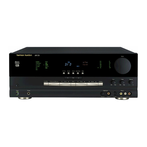
Harman Kardon AVR 220 User manual

Harman Kardon

Harman Kardon AVR 220 User manual
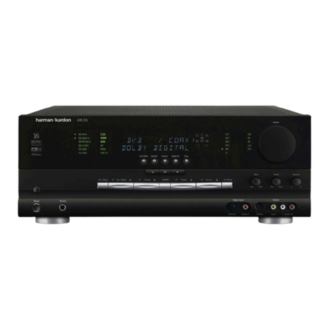
Harman Kardon AVR 151/230C User manual

Harman Kardon

Harman Kardon AVR 151/230C User manual

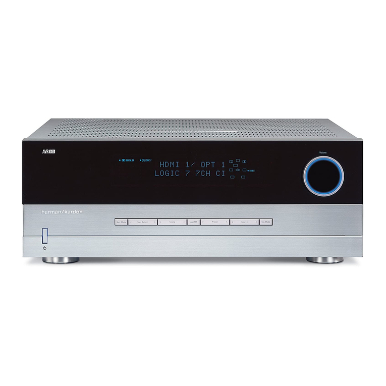
Harman Kardon AVR 7550HD User manual

Harman Kardon

Harman Kardon AVR 7550HD User manual

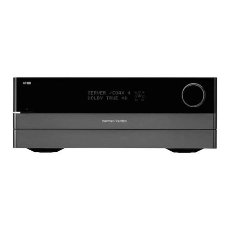
Harman Kardon NOCTURNE 330 User manual

Harman Kardon

Harman Kardon NOCTURNE 330 User manual

Harman Kardon AVR1550 User manual

Harman Kardon

Harman Kardon AVR1550 User manual

Harman Kardon BRUKSANVISNING AVR 255 Installation and operation manual

Harman Kardon

Harman Kardon BRUKSANVISNING AVR 255 Installation and operation manual

Harman Kardon AVR 430 Instruction Manual

Harman Kardon

Harman Kardon AVR 430 Instruction Manual

Harman Kardon AVR 7200 User manual

Harman Kardon

Harman Kardon AVR 7200 User manual

Harman Kardon AVR 25 User manual

Harman Kardon

Harman Kardon AVR 25 User manual

Harman Kardon AVR 7200 User manual

Harman Kardon

Harman Kardon AVR 7200 User manual

Harman Kardon AVR 125 Instructions and recipes

Harman Kardon

Harman Kardon AVR 125 Instructions and recipes

Harman Kardon ANR 142 User manual

Harman Kardon

Harman Kardon ANR 142 User manual

Harman Kardon STEREO RECITAL TA224 Operating and maintenance manual

Harman Kardon

Harman Kardon STEREO RECITAL TA224 Operating and maintenance manual

Harman Kardon AVR 145 Service manual

Harman Kardon

Harman Kardon AVR 145 Service manual

Harman Kardon AVR 430 User manual

Harman Kardon

Harman Kardon AVR 430 User manual

Harman Kardon AVR 445 User manual

Harman Kardon

Harman Kardon AVR 445 User manual

Harman Kardon AVR 7300 User manual

Harman Kardon

Harman Kardon AVR 7300 User manual

Harman Kardon AVR 125 User manual

Harman Kardon

Harman Kardon AVR 125 User manual

Harman Kardon NOCTURNE 330 User manual

Harman Kardon

Harman Kardon NOCTURNE 330 User manual

Harman Kardon AVR 147 User manual

Harman Kardon

Harman Kardon AVR 147 User manual
Harman Kardon AVR 235 User manual

Harman Kardon

Harman Kardon AVR 235 User manual

Harman Kardon AVR 435 User manual

Harman Kardon

Harman Kardon AVR 435 User manual

Harman Kardon AVR 3600 User manual

Harman Kardon

Harman Kardon AVR 3600 User manual

Harman Kardon AVR 3650 User manual

Harman Kardon

Harman Kardon AVR 3650 User manual

Popular Receiver manuals by other brands

Epson S1C05251 Technical manual

Epson

Epson S1C05251 Technical manual

Em-Trak R100 product manual

Em-Trak

Em-Trak R100 product manual

Sokkia GSR2700 ISX Configuration

Sokkia

Sokkia GSR2700 ISX Configuration

Kenwood R-600 instruction manual

Kenwood

Kenwood R-600 instruction manual

Bosch LE10 user manual

Bosch

Bosch LE10 user manual

PCB Piezotronics Echo 673B01 user manual

PCB Piezotronics

PCB Piezotronics Echo 673B01 user manual

Yamaha RX-10 owner's manual

Yamaha

Yamaha RX-10 owner's manual

Absima CR2S V.2 Installation

Absima

Absima CR2S V.2 Installation

Sony STR-DN1010 - Multi Channel Av Receiver Quick setup guide

Sony

Sony STR-DN1010 - Multi Channel Av Receiver Quick setup guide

Pyle PPRE70BT user manual

Pyle

Pyle PPRE70BT user manual

Pioneer AVH-Z5000DAB Operation manual

Pioneer

Pioneer AVH-Z5000DAB Operation manual

Denon AVR-687 Dimensions

Denon

Denon AVR-687 Dimensions

Delta Electronics RA1010-SAODT-IL Specifications

Delta Electronics

Delta Electronics RA1010-SAODT-IL Specifications

GoRave AR5 owner's manual

GoRave

GoRave AR5 owner's manual

Magenta MULTIVIEW XR2000 Quick reference & setup guide

Magenta

Magenta MULTIVIEW XR2000 Quick reference & setup guide

LG MDD64-A0U owner's manual

LG

LG MDD64-A0U owner's manual

Panasonic RF-NA06R operating instructions

Panasonic

Panasonic RF-NA06R operating instructions

Circle Prime Manufacturing CP-03276 installation instructions

Circle Prime Manufacturing

Circle Prime Manufacturing CP-03276 installation instructions

manuals.online logo
manuals.online logoBrands
  • About & Mission
  • Contact us
  • Privacy Policy
  • Terms and Conditions

Copyright 2025 Manuals.Online. All Rights Reserved.