manuals.online logo
Brands
  1. Home
  2. •
  3. Brands
  4. •
  5. Harman Kardon
  6. •
  7. Tuner
  8. •
  9. Harman Kardon The Citation Fifteen User manual

Harman Kardon The Citation Fifteen User manual

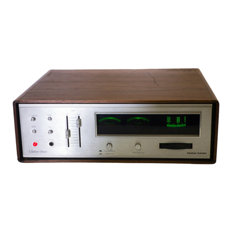
The
Citation
Fifteen
Professional
FM/Stereo
FM
Tuner
harman
/kardon
Instruction
Manual
THE
MUSIC
COMPANY
TABLE
OF
CONTENTS
PAGE
TTROCUGHON.-
oes
eden
ia
oP
SUAS
ore
nchoues
ae
een
una
iene
bagacees
2
Oltstanding:
Peatires:
i456..0.0
2
dsns
ieee
tee
a
cove
guetseds
2
MV
ADEA
EY.”
SPOUEY
*
Fon
eo
ue
eect
attain
tire
gate
ete
eaten
a
dil
Sabet
he
gi
3
PENANG
jcttiniaca
A
ay
ail
ty
aig
dean
hh
nh
oe
eGo
na
hie
eatin
each
lp
Olt
ectiene
eats
3
DEEVICE:
ious
on
these
maaan
w
Auten
nied
ues
wie
Seat
detecting
ose
when
ote,
3
Taba
enGiits
pian
ohn
s
pena
tens
ek
cece
eda
Poewnte
eta
4
Power
Requifements
\.4.6.cc
sda
ases
och aia
lee
ace
bd
Se
RO
SS
wore
4
AC
Convenience
Receptacle
..........0...
0.000.
c
cece
eeu.
4
MENUS
seta
aa
Penh
Arai
taeih
a
eit
de
cacane:
Seah
de
Meis
sine
tetas
oa
noted
4
SPAT
OTR
aa
hoa
gt
Gc
craeaneh
Bate
Ue
eae
rac
gs
Stare
al
Rte
Senda
hs
pega
deth
4
Choice
of
Transmission
Line...
..........................
5
Grounding
the
Antenna
.........0..
0.00
cece
cee
eee
ceee
5
Ouipul“Gonne
Crone)
sic
iscg
she.
naw
hd
ced
oe
be:
Kowa
Peeanee
RG
awa
weas
5
Variable:
Quinuti(h
8
°R)
cu
ancwtane
tees.
weet
cue
eawne
eres
5
Fused)
OUlgUE:
3
cece
Poca
Piucte
wdcnin
dha
dene.
sae
Leen
dea
B
ora
MeCod
er
sci.
cases
ng
aral
arte dale
a
eaca
eke
oH
kab
dete
te
8
PBDOVONI,
%
Gaxcsabaseusie
thule
iin
oor
taseen
achive
edt
hawk
eee
8
Dolby
advd
Govan
cia
ian
wee
oot
etaetntdecen
ene
tied
8
PAGE
Description
of
Controls
.........
0.0.0
ccc
ccc
cece
ce
eenveucceus
8
POWER
SWItOll
4.24
tio.
ee
lira
bude
heed
oe,
AG
bai
nee
bee
8
Gain
Gon
trols:
(LR)
ing
niles
e
ng
Socks
Bk
Aine
Adin
hed
w
fork
8
Stereo
Indicator
vawicdvexenpi
sad
nines
wadesorerpankeuuces
8
Stereo
Automatic/Monophonic
Switch....................
8
Stereo
Threshold
Control
........
0.0.0...
0c.
e
eee
eee
ee
8
Ext,
Dolby:
NR:
Switch:
2
vadiid
eh
4s
Soehe
lena
ecedenn
ba
gus
9g
Stereo
Noise
Filter
Switch
.......0....
00.
cceccecaccuvvuees
9
VETS
OWEN
toes
Feo
rad
Sea
Goat
weakens
b>
dene
pees
as
wos
oeteaieres
at
9
Muting
Threshold
Control
...........00
0000.
c
cee
ee ee ee
9
Level
Set.
Fone
Switch
14
eG
s6:c1ey
ewe
Uke
Se
eld
eh
ean
nds
9
Dial
Gales.
aaa
uies
shu
Sina
aah
ekg,
6
anesad
tale
See
4
tebe
Ba
Sake
oat
ae
bs
9
Tuning
Meter
....5565..000
000s
suas
entrants
&
Cot
Se
rhea
soso
itra
as
a
et
ate
10
MUMS
TING
WMELER
co
ahaa
k
ta
ne
ake
ew
hE
Gath
have
aaa
soe
eek
10
Antenna
Orientauon
25.2
i
4)'n.00
ae
2
Seo
OR
eee
ut
REA
eee
10
PAA
T
EDN
ie
ys
2
Saath
a
ctoarte
totes
Sestak
ns
ddd
nn
hee
ina
hosp
eos
ite
Seat
eens
ae
10
Numi:
Weak
Stations
i060
oes
deine
weet
iG
ona
eak
sen
ha
ne
aedta
11
Panis
Mechanism
2:32)
go
aeos
Waeee
wakes
Ou
Be
aoe
debe
s
11
LIST
OF
ILLUSTRATIONS
Rear
Panel
yo
eda
es.
du
eens
aee
xd
Front
Panel
....................
INTRODUCTION
Your
new
Citation
Fifteen
tuner
is
part
of
a
family
of
high
fidelity
equipment
deliberately
designed
to
effect
breakthroughs
in
the
quality
of
sound
available
in
your
home.
The
Citation
Fifteen
tuner
has
cre-
ated
new
standards
against
which
all
other
tuners
will
be
measured.
Starting
with
the
most
advanced
concepts
in
electronic
technology,
.
Harman/Kardon
engineers
developed
new
instrumentation
and
new
features.
The
introduction
of
the
Citation
Fifteen
is
significant.
for
us...and
for
you.
SOME
OF
THE
FEATURES
YOU
ARE
ABOUT
TO
ENJOY
ARE:
¢
A
revolutionary
QUIETING
METER
(patent.
pending).
that
meas-
ures
the
signal-to-noise
ratio
of
the
incoming
signal.
¢
Optimum
phase
linearity
in
the
RF
and
IF
sections,
providing
an
audio
signal
virtually
free
from
IM,
THD
and
phase
distortion
that
continues
the
Citation
tradition
of
“straight
wire
with
gain’.
Mullti-
‘
plex
phase-locked
loop
circuits
that
sense
and
quantify
phase
error
in
incoming
pilot
signals
and
automatically
make
corrections.
PLUS
THESE
OUTSTANDING
FEATURES:
FOUR
SECTION
GANG
FM
FRONT
END.
Suppression
is
more
than
100
db
eliminating
all
spurious
responses.
IF
FILTER
with
sealed
9
pole
phase
linear
LC
network
combines
excellent
phase
linearity
with
outstanding
alternate
channel
rejection.
IF
STRIP
with
2
extremely
high
gain
ICs
provides
extraordinary
hard
limiting
of
noise.
RATIO
DETECTOR
of
unique
design
ensures
precision
linearity
and
exceedingly
low
distortion.
SPECIAL
WIDEBAND
CIRCUITRY
permits
feeding
the
composite
signal
into
external,
discrete,
4
channel
stereo
adapter
without
loss
of
phase
linearity
or
amplitude.
400
CYCLE
CALIBRATION
REFERENCE
TONE
adjusted
in
ampli-
tude,
equivalent
to
50%
modulation,
facilitates
level
setting
of
reel-to-reel
or
cassette
tape
recorders.
CENTER
TUNING
METER
augments
quieting
meter
for
lowest
dis-
tortion
point.
FM
STEREO
NOISE
FILTER
eliminates
background
noise
from
weak
signals.
WARRANTY
POLICY
We
warrant
each
factory
wired
tuner
to
be
free
from
defects
in
material
and
workmanship
under
normal
use
and
service,
and
in
accordance
with
the
conditions
set
forth
below.
Should
a
defect
occur
within
the
period
specified,
and,
providing
the
unit
is
returned
to
either
HARMAN/KARDON
or
an
authorized
HARMAN/KARDON
warranty
station,
transportation
prepaid,
and
which
our
examination
shall
disclose
to
our
satisfaction
to
be
defective,
we
will,
for
a
period
of
two
(2)
years
from
date
of
original
purchase,
either
replace
or
repair
and
install
any
defective
parts
free
of
charge.
To
obtain
service
under
the
terms
of
this
policy,
it
is
necessary
for
you
to
retain
your
ORIGINAL
BILL
OF
SALE.
In
the
event
your
equipment
requires
service
during
the
warranty
period,
only
presentation
of
your
original
bill
of
sale
to
either
a
factory-authorized
repair
agency
or
the
factory,
itself,
will
insure
your
rights
under
the
policy,
as
outlined
in
this
manual.
The
Citation
warranty
does
not
include
packaging
or
transportation
charges
to
and
from
the
factory
or
authorized
warranty
repair
station.
This
warranty
is
not
applicable
to
any
unit
which
shall
have
been
repaired
or
altered
in
any
way
so
as,
in
our
judgment,
to
affect
its
reliability
or
stability
or
general
performance
or
has
been
subject
to
neglect,
misuse,
abuse,
negligence
or
accident;
or
which
has
had
the
serial
number
altered,
effaced
or
removed.
Neither
shall
this
warranty
apply
to
any
instrument
which
has
been
connected
other
than
in
ac-
cordance
with
instructions
furnished
by
us.
This
warranty
is
in
lieu
of
all
other
warranties,
expressed
or
implied,
and
of
all
other
obligations
or
liabilities
on
our
part,
and
we
neither
assume
nor
authorize
any
representative
or
other
person
to
assume
for
us
any
other
liability
in
connection
with
the
sale
of
this
instrument.
UNPACKING
After
unpacking
the
Citation
Fifteen,
inspect
it
carefully
for
signs
of
transit
damage.
The
tuner
was
subjected
to
numerous
quality
con-
trol
tests
and
inspections
prior
to
packing
and
should
therefore
be
in
perfect
operating
condition.
If
damage
is
visible,
notify
your
dealer
at
once.
If
the
tuner
was
shipped
to
you,
notify
the
transportation
com-
pany
without
delay.
HARMAN/KARDON
will
cooperate
with
you
in
such
instances,
but
only
YOU
can
recover
from
the
carrier
for
damage
incurred
during
shipment.
SERVICE
HARMAN/KARDON
has
a
special
customer
service
division
to
answer
all
questions
pertinent
to
the
installation
and
operation
of
your
unit.
Please
feel
free
to
write
to
us
at
any
time
for
prompt
and
com-
plete
advice.
Hf
your
problem
cannot
be
resolved
through
our
combined
efforts,
we
may
refer
you
to
a
local
authorized
repair
agency
or
authorize
the
return
of
your
unit
to
the
factory.
To
aid
us
in
selecting
a
service
station
convenient
to
you,
it
would
be
helpful
if
you
would
indicate
the
major
city
closest
to
your
home.
Please
address
your
inquiry
to:
Customer
Service
Department
HARMAN/KARDON,
INC.
Plainview,
New
York
11803
Be
sure
to
include
the
model
and
serial
number
of
your
unit.
In
the
event
it
must
be
returned,
an
authorization
form
and
proper
packing
instructions
will
be
forwarded
to
you.
This
authorization
form
MUST
BE
RETURNED
with
your
unit.
UNDER
NO
CIRCUMSTANCES
SHOULD
YOUR
UNIT
BE
SHIPPED
TO
THE
FACTORY
WITHOUT
PRIOR
AUTHORIZATION.
INSTALLATION
The
Citation
Fifteen
produces
very
little
heat
and
may
be
installed
without
regard
to
normal
ventilation
requirements.
However,
if
you
are
installing
the
unit
in
custom
cabinetry,
it
is
recommended
that
you
avoid
placing
the
tuner
directly
over
heat
producing
units
such
as
a
basic
amplifier
or
tube-type
preamplifier.
(A
handsome
walnut
en-
closure
or
custom
cabinet
is
available
from
your
dealer
as
optional
equipment.}
POWER
REQUIREMENTS
The
AC
line
cord
plug
may
be
inseried
into
any
outlet
furnishing
117
volts,
50/60
Hz
AC
current.
(Voltage
may
vary
between
105
and
125
volts.)
For
use
in
areas
which
provide
210
to
250
volts
AC,
50/60
Hz
cur-
rent,
the
Citation
Fifteen
may
be
rewired
as
shown
on
the
schematic
diagram
in
the
Technical
Manual.
However,
rewiring
should
be
done
only
by
an
authorized
technician.
Unless
otherwise
indicated,
all
Citation
Fifteen
tuners
have
been
factory
wired
to
operate
at
a
nominal
voltage
of
117
volts
AC.
AC
CONVENIENCE
RECEPTACLE
An
AC
convenience
receptacle
is
provided
on
the
rear
panel
of
your
Citation
Fifteen.
Any
equipment
connected
to
this
receptacle
will
be
controlled
by
the
on/off
switch
of
the
tuner.
It
is
therefore
recom-
mended
that
this
receptacle
be
used
for
tuner
associated
accessories
such
as
an
antenna
rotator,
antenna
booster,
quad
decoder,
etc.
FUSE
The
Citation
Fifteen
is
protected
by
a
STANDARD
FAST
BLOW
fuse
located
on
the
rear
panel.
If
this
fuse
is
blown,
it
is
to
be
replaced
only
with
one
of
the
SAME
TYPE
and
SAME
RATING.
It
is
important
to
note
that
replacing
the
FAST
BLOW
FUSE
with
a
slow
blow
type
or
with
a
fuse
of
higher
rating,
WILL
PREVENT
MAXIMUM
PROTECTION
of
the
tuner
and
could
result
in
severe
damage.
Such
damage
will
not
be
covered
by
the
Factory
Warranty.
VOLTAGE
(50/60
Hz)
FUSE
TYPE
FUSE
RATING
105-125
VAC
3AG
or
AGC
1.5
Amperes
210-250
VAC
3AG
or
AGC
1.0
Amperes
ANTENNA
In
selecting
an
antenna
system
for
use
with
your
Citation
Fifteen
please
keep
in
mind
that
your
tuner’s
full
potential
and
performance
capability
can
only
be
achieved
when
you
provide
the
best
possible
signal
to
the
antenna
terminals.
If
you
live
in
a
metropolitan
area
(or
if
you
wish
to
receive
signals
from
many
directions)
an
ordinary
crossed
dipole,
conical
or
three
element
in-line
antenna
should
serve
adequately.
The
three
or
four
element
in-line
(uni-directional)
type
is
the
most
satisfactory
of
the
group,
but
due
to
its
high
directivity,
it
becomes
necessary
to
include
an
antenna
rotator
to
change
the
direction
of
the
antenna
for
best
reception,
For
near-fringe
and
fringe
reception,
a
six-to-eight-element
log-
periodic
or
Yagi
is
recommended.
Both
types
are
excellent
and
offer
superior
front-to-back
ratio,
(ratio
of
forward
pickup
to
that
at
the
rear,
greater
gain
and
rejection
of
noise.
Both
types
are
highly
direc-
tional
and
require
a
rotator.
Far
fringe
reception
requires
an
antenna
with
eight
or
ten
elements.
This
type
antenna
is
usually
quite
heavy
and
requires
extra
support
and
bracing
when
installed.
Remember,
FM
stereo
reception
requires
greater
gain
than
standard
monophonic
FM.
It
is
therefore,
advisable
to
purchase
the
antenna
which
can
“pull
in”
a
station
with
the
greatest
gain
and
lowest
possible
noise.
Are
there
high-rise
buildings
in
your
area?
Water
towers?
Gas
tanks?
Mountains?
They
can
all
cause
serious
reception
problems
by
reflecting
FM
signals
which,
when
received,
will
result
in
audible
distortion.
This
form
of
distortion
is
known
as
multipath
interference
and
is
similar
to
“ghosts”
on
your
TV
set.
Multipath
interference
can
be
reduced
or
eliminated
by
purchasing
a
highly
directional
antenna
with
a
rotator.
Proper
orientation
of
the
antenna
may
tune
out
multipath
completely,
or
alternate
it
below
audibility.
If
installed
properly,
an
outside
antenna
will
reject
unwanted
sig-
nals,
local
noise,
multipath
interference,
and
provide
greater
signal
strength
than
any
elementary
type.
Increased
signal
strength
usually
results
in
the
reception
of
additional
stations
with
amazing
clarity.
Nj
TRANSMITTER
CHOICE
OF
TRANSMISSION
LINE
The
major
types
of
antenna
lead-in
wire
available
are
flat
ribbon,
tubular,
foam,
coaxial
and
encapsulated.
Each
type
has
specific
ad-
vantages
which
must
be
weighed
against
the
costs
involved
in
each
installation.
A
high-quality
100-mil,
20-gauge,
polyethylene
300-ohm
twin-lead
is
usually
satisfactory
for
most
installations.
Tubular
or
foam
line
provides
better
protection
than
flat
ribbon
against
the
elemenis
and
industrial
smog.
Coaxial
lead-in
is
useful
for
multiple-set
installations
and
to
reduce
pick-up
of
extraneous
noise.
Coaxial
line
has
a
higher-
loss
characteristic
than
twin-lead
(tubular
or
foam),
but
the
loss
is
constant,
and
can
easily
be
compensated
for
through
the
use
of
a
more
powerful
antenna.
The
encapsulated
300-ohm
line
(also
referred
to
as
300-ohm
shielded
lead)
has
excellent
weather-resistant
characteristics
and
a
somewhat
lower
loss
factor
than
coaxial.
To
avoid
signal
loss,
the
transmission
line
should
be
kept
as
short
as
possible
and,
preferably,
should
run
vertically
down
to
the
set.
When
using
an
external
antenna
with
300
ohm
twin
lead,
connect
both
leads
to
the
two
300
ohm
antenna
terminals
on
the
rear
of
your
tuner.
If
your
external
antenna
is
connected
with
75
ohm
coaxial
cable,
connect
between
the
75
ohm
and
GND
terminal,
with
the
outer
conductor
or
shield
of
the
cable
connected
to
the
GND
terminal.
GROUNDING
THE
ANTENNA
An
antenna
can
act
like
a
lightning
rod
because
it
is
often
the
highest
metal
structure
on
the
roof.
It
must
therefore
be
grounded.
Attach
a
heavy-gauge
aluminum
wire
to
the
mast
and
a
lightning
arrestor
to
the
transmission
line
where
it
enters
the
building.
On
apartment-roof
installations,
a
lightning
arrestor
may
be
at-
tached
to
the
mast,
and
another
to
the
transmission
line
where
it
enters
the
building.
In
general,
it
is
always
advisable
to
keep
the
lightning
arrestor
outside
the
home
interior.
Where
ground
rods
are
used,
they
should
be
at
least
four
feet
long
and
deeply
sunk
into
the
ground.
When
selecting
an
FM
antenna
system
remember
the
following:
1.
The
proper
antenna
should
be
used
for
a
given
location.
The
further
you
are
located
from
the
FM
transmitter,
the
more
gain
the
antenna
must
offer.
2.
The
antenna
should
have
uniform
signal
level
across
the
entire
frequency
range
it
covers.
3.
Antenna
placement
is
extremely
important
for
maximum
signal
reception.
4,
The
installation
must
be
rigid
to
avoid
damage
to
the
roof,
chim-
ney,
wall
or
other
property.
5.
Careful
routing
of
the
lead-in
line
to
avoid
pick
up
of
local
inter-
ference.
A
poorly
routed
lead-in
line
(which
touches
metal
portions
of
the
house,
etc.)
will
reduce
signal
strength
by
a
significant
margin.
OUTPUT
CONNECTONS
The
Citation
Fifteen
provides
five
different
output
receptacles,
each
designed
for
a
specific
function.
One
receptacle
{Tape
Out)
is
located
on
the
front
panel
and
uses
a
standard
%4”
phone
jack.
The
other
four,
are
located
on
the
rear
panel.
All
receptacles
accept
stand-
ard
RCA
phono
jacks.
In
making
your
installation,
you
may
use
one
or
more
pair,
depending
on
your
requirements.
VARIABLE
OUTPUT
(L&R)
These
receptacles
may
be
connected
either
to
the
preamplifier
or
directly
to
the
basic
amplifier.
In
either
case,
the
level
of
signal
at
these
receptacles
is
controlled
by
the
GAIN
CONTROLS
on
the
front
panel
of
your
tuner.
These
Gain
Controls
may
be
used
when
adjust-
-
ing
the
level
of
your
tuner
to
match
the
level
of
other
source
material
connected
to
your
system,
such
as
phonograph,
tape
recorder,
etc.
FRONT
PANEL
EXTERNAL
DOLBY
NR
LEVEL
SET
BYNR
Tq
LEFT
O
O
sce
-—s-""
POWER
ON/
OFF
MUTE
oO
—
~-4—.
TAPE
OUT
eens
O\|
©@
ane
©
TE!
;
f
tation
Mteen
EL
STEREO
AUTOMATIC
Cithtion
fiftee
ceNebticale
STEREO
NDISE
FILTER
harman/kardon
TAPE
,
POWER
|
[POWER
OUT
MUTE
FUNCTION
TUNING
INDICATOR]
[SWITCH]
[RECEPTACLE]
|SWITCH
SWITCH
REAR
PANEL
VARIABLE
MUTING
STEREO
75
OHM
SWITCHED
OUTPUT
THRESHOLD]
[THRESHOLD
ANTENNA
CONVENIENCE
LSA
RECEPTACLES
CONTROL
CONTROL
ERMINALS
RECEPTACLE
FUSE
FIXED
DOLBY
|
300
OHM
OUTPUT
RECEPTACLES
ANTENNA
RECEPTACLES
TERMINALS}
TO
LINE
QUAD
CORD
DECODER
FIXED
OUTPUT
(L&R)
These
receptacles
provide
the
full
output
of
your
tuner
and
are
NOT
controlled
by
the
GAIN
CONTROLS.
They
should
be
connected
to
either
your
preamplifier
or
to
a
tape
recorder.
They
should
NEVER
be
connected
directly
to
a
basic
amplifier.
TO
QUAD
DECODER
The
Citation
Fifteen
anticipates
the
further
development
and
standardization
of
four
channel
FM
broadcasting.
The
tuner
provides
an
output
receptacle
to
connect
FM
four
channel
signals
to
a
decoding
device
suitable
for
any
anticipated
quadriphonic
broadcast
system.
TAPE
OUT
The
front
panel
receptacle
is
identical
to
the
FIXED
OUTPUT
located
on
the
rear
panel.
It
has
been
located
on
the
front
panel
as
well
to
provide
instant
accessibility
for
temporary
connection
to
a
tape
recorder.
DOLBY
NR
Your
tuner
is
provided
with
Dolby
In
and
Out
receptacles.
These
may
be
used
when
you
wish
to
listen
to
an
FM
broadcast
which
has
been
processed
with
the
Dolby
system.
Connect
the
two
(2)
Dolby
OUT
receptacles
to
the
input
of
your
external
Dolby
processor
and
the
two
(2)
Dolby
IN
receptacles
from
the
output
of
your
external
Dolby
processor.
DESCRIPTION
OF
CONTROLS
Each
control
and
tuning
indicator
of
the
Citation
Fifteen
has
been
designed
to
perform
a
specific
useful
function
—
either
individually
or
in
combination
with
others.
In
order
to
obtain
the
best
possible
performance
from
your
tuner,
we
suggest’
that
you
read
the
following
so
that
you
may
take
advantage
of
the
full
potential
of
these
controls
and
indicators.
POWER
SWITCH
This
switch
provides
AC
power
to
the
tuner
and
to
the
AC
con-
venience
receptacle
on
the
rear
panel.
When
in
the
‘‘ON”
position,
the
pilot
light
jewel
below
the
switch
and
the
meter
and
dial
scale
win-
dows
will
be
illuminated.
.
GAIN
CONTROLS
(Left
&
Right)
These
control
the
output
level
of
the
tuner
at
the
VARIABLE
OUT-
PUT
receptacles
on
the
rear
panel.
If
the
tuner
is
used
in
conjunction
with
a
basic
amplifier
only,
these
controls
will
adjust
the
system
gain.
When
connected
to
a
preamplifier,
these
controls
may
be
preset
to
match
the
level
of
other
signal
sources
connected
to
your
system.
The
volume
control
of
your
preamplifer
may
then
be
used
as
the
master
gain
control
of
your
system.
STEREO
INDICATOR
The
“Stereo
Indicator’
light
indicates
when
the
Citation
Fifteen
is
reproducing
stereo
FM
broadcasts.
STEREO
AUTOMATIC/MONOPHONIC
SWITCH
Under
normal
use
for
all
broadcasts,
the
stereo
auto
switch
should
be
in
the
“OUT”
(stereo
Auto)
position.
Your
tuner
is
equipped
with
a
stereo
sensing
circuit
which
will
auto-
matically
determine
whether
your
unit
is
receiving
monophonic
or
stereophonic
broadcasts,
and
then
automatically
adjust
the
mode
of
operation.
If
the
station
is
transmitting
stereo,
your
tuner
will
automatically
switch
on
the
multiplex
section
and
you
will
hear
the
broadcast
in
full
stereo.
Should
the
station
conclude
broadcasting
in
stereo,
your
tuner
will
automatically
switch
back
to
monophonic
reception.
Should
you
receive
a
weak
stereo
signal
whose
quality
has
been
degraded
by
noise
or
poor
signal
conditions,
and
you
wish
to
listen
to
this
stereo
broadcast
monophonically,
place
the
stereo
auto
switch
to
the
“IN”
position.
STEREO
THRESHOLD
CONTROL
This
rear
panel
control
can
be
adjusted
to
determine
the
number
of
stereo
stations
the
tuner
will
reproduce
when
in
the
“OUT”
position
of
the
stereo
Auto/Mono
switch.
In
the
full
counterclockwise
position,
the
automatic
switching
circuits
have
maximum
sensitivity
and
all
stereo
stations
within
the
range
of
the
tuner
will
be
reproduced.
However,
due
to
weak
signals
(or
their
distance
from
your
antenna)
some
stations
will
contain
noise
levels
which
degrade
performance
when
reproduced
in
stereo.
In
order
to
reproduce
these
stations
monophonically
(when
in
the
“OUT”
position
of
the
stereo
Auto/Mono
Switch],
rotate
the
STEREO
THRESHOLD
control
clockwise
until
only
good
quality
stereo
stations
are
reproduced.
EXT.
DOLBY
NR
SWITCH
When
an
FM
station
broadcasts
a
Dolby
encoded
program,
it
may
be
decoded
by
use
of
an
external
Dolby
processor.
If
you
use
an
external
processor,
the
Dolby
switch
when
depressed,
will
decode
an
encoded
program.
If
the
Dolby
button
is
depressed
without
an
external
proc-
essor
connected,
you
will
get
zero
output
from
your
speaker
system.
STEREO
NOISE
FILTER
SWITCH
Stereophonic
FM
broadcasts
require
greater
signal
strength
at
the
antenna
terminals
(as
compared
to
monophonic
FM
broadcasts).
Weak
or
distant
stereo
signals
will
naturally
contain
more
noise
than
a
mono-
phonic
signal
of
similar
strength.
The
Citation
Fifteen
STEREO
NOISE
FILTER
will
reduce
or
eliminate
this
undesirable
noise.
In
the
“OUT”
position,
the
switch
has
no
effect.
Filtering
is
provided
in
the
“IN”
position,
MUTE
SWITCH
The
MUTE
circuit
reduces
the
audible
noise
(hissing
or
rushing
sound)
found
between
stations.
To
eliminate
interstation
noise,
push
the
MUTE
Switch
“IN”.
To
defeat
the
circuii,
push
the
switch
again.
It
will
return
to
the
“OUT”
position.
MUTING
THRESHOLD
CONTROL
This
rear
panel
control
adjusts
the
level
at
which
muting
action
will
take
place.
Minimum
muting
action
occurs
in
the
full
counterclock-
wise
position.
Maximum
muting
is
achieved
in
the
full
clockwise
position.
The
full
clockwise
position
will
also
eliminate
stations
with
poor
transmission
quality.
The
control
should
be
adjusted
to
the
point
where
you
receive
only
those
stations
which
meet
your
standards
of
broadcast
quality.
LEVEL
SET
TONE
SWITCH
The
LEVEL
SET
TONE
switch
on
the
front
panel
activates
a
gen-
erator
which
produces
a
sine
wave
test
tone
of
400
Hz
at
a
level
equivalent
to
50%
of
full
modulation
of
an
FM
signal.
“Off-the-air”
tape
recordings
can
be
made
with
complete
assurance
of
correct
levels
by
using
the
test
tone
as
a
recording
level
reference.
After
activating
the
LEVEL
SET
TONE
adjust
the
record
level
con-
trols
of
your
tape
recorder
so
the
record
level
meters
or
other
indi-
cators
on
your
tape
recorder
register
a
level
of
“0”
VU.
At
this
setting
recordings
can
be
made
with
optimum
signal-to-noise
ratio
and
the
distribution
of
dynamic
level
changes
in
music
will
be
properly
captured.
Recorders
vary
in
the
saturation
and
overload
characteristics
of
their
record
amplifiers
which
affect
the
occurrence
of
distortion
in
the
recording
process.
You
may
find
with
your
recorder
that
with
the
“0”
VU
setting
of
the
record
indicators,
the
reference
tone
is
too
high.
While
signal-to-noise
ratio
is
usually
optimum
at
the
“0”
VU
setting,
signal
vs.
distortion
typically
improves
at
lower
recording
levels
(down
to
—8
VU).
With
some
experience
you
will
find
a
recording
level
within
these
values
that
provides
a
combination
of
high
signal-to-
noise
ratio
and
low
distortion
that
is
right
for
you
and
your
recorder.
Because
of
the
variation
of
levels
required
by
different
tape
re-
corders,
it
is
advisable
to
experiment
with
the
record
level
controls
on
your
recorder.
However,
once
this
level
is
determined
it
can
re-
main
constant.
DIAL
SCALE
The
DIAL
SCALE
consists
of
a
large
drum
which
rotates
in
con-
junction
with
the
knurled
flywheel.
The
DIAL
SCALE
is
calibrated
with
an
FM
frequency
scale
(88-108
mHz)
and
a
logging
scale
{0-10}.
Most
FM
stations
operate
at
frequencies
which
are
not
whole
numbers
(such
as
96.3
mHz)
as
compared
to
96
mHz.
Ideally,
each
megacycle
division
on
the
frequency
scale
should
be
divided
into
10
parts
to
enable
the
user
to
pinpoint
the
location
of
the
station.
This
would
require
a
dial
scale
which
would
be
impractical.
The
logging
scale
which
is
divided
into
100
equal
parts
provides
a
means
of
finding
your
favorite
station,
once
you
have
noted
its
position
on
the
logging
scale.
For
example,
in
New
York
City,
WQXR
operates
at
96.3
mHz.
After
locating
this
station
through
the
use
of
the
frequency
scale
(between
96
and
98
mMz)
the
pointer
may
fall
on
42
on
the
logging
scale.
Make
a
note
of
this
setting.
For
future
tuning
to
WQXR
simply
set
the
pointer
to
42
on
the
logging
scale.
TUNING
METER
All
FM
broadcast
stations
are
assigned
a
frequency
by
the
Federal
Communications
Commission.
The
signals
from
these
stations
extend
equally
above
(+)
and
below
(—)
the
assigned
frequency.
The
fre-
quency
spectrum
is
called
the
“pass
band”’.
The
tuning
meter
of
the
Citation
Fifteen
(when
centered)
is
tuned
to
the
exact
center
of
the
pass
band.
However,
you
may
be
detuned
slightly
(either
+
or
—)
and
still
not
experience
degradation
of
the
quality
of
sound
by
remaining
within
the
limits
of
the
pass
band.
Only
when
detuned
enough
to
reach
the
edge
of
the
pass
band
will
the
signal
become
noisy,
distorted
and
finally
disappear.
It
is
important
to
note
that
it
is
NOT
ALWAYS
NECESSARY
to
be
tuned
to
the
EXACT
center
of
an
assigned
pass
band
to
obtain
clean,
undistorted
sound.
QUIETING
METER
“Quieting”
is
a
term
used
in
the
measurement
of
the
relative
signal-
to-noise
ratio
of
a
broadcast
signal.
Conventional
signal
strength
or
center
channel
meters
do
not
in-
dicate
the
quality
of
the
received
signal
—
simply
their
strength
and
pass
band
accuracy.
Harman/Kardon’s
extraordinary
QUIETING
METER
actually
indicates
or
‘reads’
the
signal-to-noise
ratio
or
the
QUALITY
of
the
received
signal.
Maximum
deflection
of
this
meter
(highest
number)
represents
the
best
listening
point
within
the
pass
band
EVEN
IF
THE
TUNING
METER
IS
NOT
AT
THE
CENTER
OF
THE
PASS
BAND.
As
you
detune
closer
to
the
edge
of
a
station’s
pass
band,
the
QUIETING
METER
will
immediately
reflect
the
increased
noise
and
distortion.
The
QUIETING
METER
will
“ALWAYS”
agree
with
what
you
hear
and
will
“ALWAYS”
indicate
the
best
tuning
point.
10
The
preceding
paragraphs
provide
a
basic
and
concise
description
of
the
function
and
operation
of
the
controls
and
indicators
of
the
Citation
Fifteen.
They
have
been
described
under
what
are
considered
‘normal’
operating
conditions.
However,
abnormal
conditions
sometimes
do
occur
and
could pose
some
special
problems.
The
following
material
deals
with
some
key
problems
which
could
arise
under
“abnorma!”
conditions
and
the
methods
which
can
be
employed
to
solve
them.
PWIETING
ANTENNA
ORIENTATION
If
your
antenna
system
uses.
a
rotation
device,
the
best
antenna
orientation
will
be
achieved
when
the
QUIETING
METER
indicates
the
greatest
steady
deflection
(highest
number).
Rotate
the
antenna
in
the
general
direction
of
the
transmitting
station’s
antenna
and
consult
the
QUIETING
METER
to
make
fine
adjustments
of
the
antenna’s
position.
MULTIPATH
“Multipath”
is
a
form
of
audible
distortion
caused
when
a
signal
and
its
echoes
reach
a
receiver
a
fraction
of
a
second
apart.
(Similar
io
“ghosts”
on
your
TV
screen).
Such
distortion
can
be
caused
by
high
rise
buildings,
airplanes,
water
towers,
mountains,
etc.
Con-
ventional
signal
strength
tuning
meters
are
unable
to
provide
guidance
to
reduce
such
interference.
However,
since
multipath
signals
always
increase
background
noise,
the
QUIETING
METER
may
be
used
to
tune
both
the
Citation
Fifteen
and
your
antenna
to
eliminate
or
drastically
reduce
multipath
inter-
ference.
TUNING
WEAK
STATIONS
When
using
the
MUTE
function
of
the
Citation
Fifteen,
most
sta-
tions
received
will
be
relatively
strong
and
have
good
signal-to-noise
ratio.
However,
when
a
“weaker”
station
is
immediately
adjacent
to
a
“stronger”
station,
it
may
be
difficult
to
tune
in
the
weaker
station
with
clarity.
In
such
situations,
the
stronger
station
may
mix
with
or
mask
the
weaker
station
even
though
the
tuning
meter
indicates
that
you
are
precisely
tuned
to
the
weaker
station.
Under
such
circum-
stances,
you
can
achieve
the
best
possible
signal
quality
from
the
11
weaker
station
by
using
the
QUIETING
METER
to
tune
away
from
the
stronger
station
while
remaining
within
the
pass
band
of
the
weaker
station.
.
TUNING
MECHANISM
The
Citation
Fifteen
does
not
employ
a
conventional
tuning
knob.
Instead,
a
solid,
knurled
flywheel
is
mounted
horizontally
for
precise,
smooth
and
accurate
tuning.
The
flywheel
is
carefully
designed
for
easy
access
and
for
extraordinarily
smooth
and
efficient
changing
of
stations.

Other manuals for The Citation Fifteen

1

Other Harman Kardon Tuner manuals

Harman Kardon HK715 User manual

Harman Kardon

Harman Kardon HK715 User manual

Harman Kardon FM-100 User manual

Harman Kardon

Harman Kardon FM-100 User manual

Harman Kardon CITATION 23 User manual

Harman Kardon

Harman Kardon CITATION 23 User manual

Harman Kardon TU9200 User manual

Harman Kardon

Harman Kardon TU9200 User manual

Harman Kardon Tempo F-10 User manual

Harman Kardon

Harman Kardon Tempo F-10 User manual

Harman Kardon CITATION 15 User manual

Harman Kardon

Harman Kardon CITATION 15 User manual

Harman Kardon TU 980 User manual

Harman Kardon

Harman Kardon TU 980 User manual
Harman Kardon Lyric F250 User manual

Harman Kardon

Harman Kardon Lyric F250 User manual

Harman Kardon Tempo F-10 User manual

Harman Kardon

Harman Kardon Tempo F-10 User manual

Harman Kardon TU9400 User manual

Harman Kardon

Harman Kardon TU9400 User manual

Harman Kardon T300X User manual

Harman Kardon

Harman Kardon T300X User manual

Harman Kardon TU930 User manual

Harman Kardon

Harman Kardon TU930 User manual

Harman Kardon The Duet T224 User manual

Harman Kardon

Harman Kardon The Duet T224 User manual

Harman Kardon TU909 User manual

Harman Kardon

Harman Kardon TU909 User manual

Harman Kardon PT2500 User manual

Harman Kardon

Harman Kardon PT2500 User manual

Harman Kardon TU905 User manual

Harman Kardon

Harman Kardon TU905 User manual

Harman Kardon CITATION 23 User manual

Harman Kardon

Harman Kardon CITATION 23 User manual

Harman Kardon CITATION 14 User manual

Harman Kardon

Harman Kardon CITATION 14 User manual

Harman Kardon F500X User manual

Harman Kardon

Harman Kardon F500X User manual

Harman Kardon The Madrigal ST350 User manual

Harman Kardon

Harman Kardon The Madrigal ST350 User manual

Harman Kardon The Citation Fifteen User manual

Harman Kardon

Harman Kardon The Citation Fifteen User manual

Harman Kardon SIGNATURE 2.0 User manual

Harman Kardon

Harman Kardon SIGNATURE 2.0 User manual

Harman Kardon TU910 User manual

Harman Kardon

Harman Kardon TU910 User manual
Harman Kardon HA160-0004-A User manual
Harman Kardon

Harman Kardon HA160-0004-A User manual

Popular Tuner manuals by other brands

Novus NVR-4204P4-H1 user manual

Novus

Novus NVR-4204P4-H1 user manual

Korg GA-30 user manual

Korg

Korg GA-30 user manual

Pioneer F-F3-J operating instructions

Pioneer

Pioneer F-F3-J operating instructions

Emerson EGT-1 user manual

Emerson

Emerson EGT-1 user manual

Audiovox TBX9850 Specifications

Audiovox

Audiovox TBX9850 Specifications

MFJ -969 DELUXE Versa Tuner II instruction manual

MFJ

MFJ -969 DELUXE Versa Tuner II instruction manual

Realistic TM-152 owner's manual

Realistic

Realistic TM-152 owner's manual

Marantz AV7703 quick start guide

Marantz

Marantz AV7703 quick start guide

Korg CA-3 owner's manual

Korg

Korg CA-3 owner's manual

Pioneer SH-D07 Service manual

Pioneer

Pioneer SH-D07 Service manual

McIntosh M85 owner's manual

McIntosh

McIntosh M85 owner's manual

Hama DT60 operating instructions

Hama

Hama DT60 operating instructions

Samsung SNR-32A user manual

Samsung

Samsung SNR-32A user manual

Snark SN-10 user manual

Snark

Snark SN-10 user manual

Inter-m PT-9107S Service manual

Inter-m

Inter-m PT-9107S Service manual

Arcam T32 Handbook

Arcam

Arcam T32 Handbook

Digital Devices Max S8 user manual

Digital Devices

Digital Devices Max S8 user manual

Rotel RT-224 owner's manual

Rotel

Rotel RT-224 owner's manual

manuals.online logo
manuals.online logoBrands
  • About & Mission
  • Contact us
  • Privacy Policy
  • Terms and Conditions

Copyright 2025 Manuals.Online. All Rights Reserved.