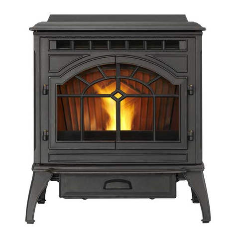
Harman Stove Company Accentra-2 User manual


This heatingappliancedoes notjust have automatic ignition,it hastotalautomatictemperature control. The
Accentra hasaninputheatrangefrom0to40,000 BTU's. This patentedfeedsystemhasamaximumfeed rateof5Ibs.
per hour and a minumum (maintenance)feed rateof .75 Ibs.per hour andthen "off'
if
necessary.The hopper holds
approximately50poundsoffuel.The unithasan easytocleancombustionsystemwithanash panthatholdsashfrom
1
tonof burnedpremiumpellets.
Thecontrolisdesignedforeasyandefficientoperation.IthasL2automaticmodesofoperationand2 manualmodesof
operation.
TheAccentrausesasmallroomsensor ratherthen awallthermostatforamoreaccuratetemperaturecontrol.
Thisunitisequippedwith severaldifferentsafetydeviceswhichwill beexplainedlaterinthismanual.With itsspecially
designedburnpotandthe"AdvanceIgnitor"AutomaticIgnitionSystem,theunitcanburnalargevarietyof biomassfuels
with varying ash content.The accordianstyle cast iron heatexchanger systemallows maximumsurfaceareafor the
mostefficientheattransfer inasmallerfirebox.
WWII
PPPWIBPPIII
DomrBnXNeW$BLI
LUdshUYL
1
SAFETYNOTICE: IFTHIS HARMANACCENTRAPELLET
I
INSPECTIONREQUIREMENTSINYOURAREA.
STOVE ISNOTPROPERLYINSTALLED.A HOUSE FlRE
MAYRESULT.FORYOURSAFETY,FOLLOWTHEINSTAL-
LATIONDIRECTIONSCONTACTLOCALBUILDINGORFlRE
OFFICIALSABOUTRESTRICTIONSAND INSTALLATION
ManualOperation 6
Table of Contents
Automatic Operation
4
Safety
testing
by
Omni Testing
Laboratory
1
ESP Control 8
I
ASTM-El509
ULC-C1482
*
Oregon-8
14-23-900
per
40CFR-60.530
sup.
part
AAA
1
Assembly
8
Installation
1
Maintenance
20
1
per
EM
method
28A
and
56
1
Trouble-Shooting
*=
I
Venting
I4
1
1
Specifications 26
1
1
WiringDiagram
27
1
I
Feeder Parts
28
I
Harman Stove Company
352Mountain HouseRoad
Halifax,
PA
17032
PartsList
Warranty

TheAccentra pelletstoveismorethanjust automaticignition,itisalsoautomatictemperature
control.Theautomatic systemwill allowthefiresizeto beadjustedto matchthe heating
needs and even put the fire out if necessary. If heat is needed after the fire is out, the
Accentra will automaticallyre-igniteand adjust the fire size to matchthe heating need.
Thetotallyautomaticroomsensor modeis recommendedbecauseof itsefficiency.
The unitcanbeswitchedbetween"AUTOand"MANUAL"atany time duringoperation.
speed.
Room Temperature Mode
In"RoomTemp Mode"heatoutputiscontrolledau-
letsfall intothe ash pan.
In"RoomTemt, Mode"a constantfuel consum~tion
1
j_i
75'
Fig.
1
Thissetting willproducemediumheatwiththe
distributionbloweron "low".
tomatically bythe RoomSensingProbe.Whenthe Room
SensingProbecallsfor heat,the stovewill increaseout-
put. When the Room Sensing Probe is getting close to
the set temperature, the stove will beginto level off out-
putandkeepthefireburningatjust the righttemperature
to maintainthat setting.
High output is determined by the feed rate set-
ting. This setting, generally on
#4,
can be increased if
higherburnratesarenecessary(Fig. 1).Theunit's maxi-
mum burn rate should not create less then 1"of ash on
rn
COMBUSTION
0
BLOWER
DISTRIBUTION
0
BLOWER
0
STATUS
0
POWER
Room Temperature Mode:
This setting will produce a room
the burn potfront edge(See Fig.4). Overfeedingis nota
temperature of
70
degrees with the distribution blower at medium
safety concern, butfuel may bewasted if unburned pel-
Thissettingwillproducecontinuousmaximumheat
outputwiththedistributionblowerat fullspeed.
Fig.
2
cally.The distributionblowerspeedwill vary accordingto
the positionof the mode selector pointer,andfire size.
1-
Stove Temperature Mode
Thisallowsfor automatic ignitionuponstart-uponly.
The unitcanthen beset at any desired setting. The heat
outputandfuelconsumptionwillremainconstantregard-
less of room temperature (See Fig
2).
The unit's maxi-
mumfeed rate should not create lessthan 1" of ash on
the burnpotfront edge. See Fig4.
The unit'slow burnor maintenancesettingisas low
as itwillgo. Itwill notgoout unlessit runsoutoffuel or is
turnedoff.
To killthefireorstopburningthestove,turntheMode
Selectorto "OFF".Thiswill causethefiretodiminishand
burn out. When the fire burns out and the stove cools
downeverythingwill stop.
Ifyoupulltheplugto shutdownthestove,all motors
will stop. This may cause incomplete combustion and
smokeinthefirebox. Iftheloaddoorisopenedthesmoke
may escape.

Ignitor Switchto"AUT0(downposition)
Make surethe unit is plugged intoa 120VAC,
60
HZ
electricalsource.Thepower lightshould
betheonlylightlit.
Fig.
3
See
Note
7.
1.
Turn Mode Selectorto "OFF".
2.
Fillhopperwith
pellets.'
3.
Clean burnpot
withscraper,ifnecessary5
4.
Ifstarting after an empty hopper, turn Feed
Adjuster to "TEST"
(forone 60 second cy~le).~
Thiswill purgepelletsintotheaugertubeandalso
allowyoutocheckthemotorsfor operation.
NOTE:
Theaugermotorwill notoperatewiththeview
door or ash pandoor open.3
1.
Fines are smallpiecesof brokenpellets (sawdust).Fines do
not flow easily and offen build up on thehopper funnel bottom
5.
Turn FeedAdjusterto
#4.4
angles. These fines can be pushed into the feeder opening
6
Flipthe IgnitorSwitchdown
intothe"AUTOH
and then fill the hopper withpellets. As the system works, they
will be burned.
position.
2.
The "TEST" cycle will operate the feeder motor for exactly
oneminute. Turningto "TEST"again and again may purge too
7.
Turn the Temperature Dial
to desired room
much fuel into the burn pot causing excessivesmoke on start-
UR.
temperature.
3.
Thefirebox lowpressureswitch~illn~tallowtheaugermotor
8.
Turn Mode Selector
to RoomTemperature or
or the ianiter element to o~erateif the view door is ooen.
4. ~djustFeed Rate. If this is your first fire or you are trying
StoveTemperature.
different pellets, set the feed adjuster to
#4,
Fig. 3. This is a
conservativenumber and will ~robablvneed to be increased.
9.
Fillhopper
with pelletsand
removeashes
as
Affer you know a feed rate setting that works well, use that
setting. Remember,
if
your feed rate is toohighyou may waste
req~ired.~
fuel.
5. Thisis usually a weekly maintenceprocedure. Cleaningthe
burnpot withthe scraper witha smallamountof new fuelin the
bottom is not a problem.First, scrape the ashes on the front of
the burn pot into the ash pan. Then scrape the holed surface
downward into the burn pot. When the stove is ignited these
scrapings will be pushed out by the feeder.
6.
Theashpan can hold theashes from approximately
1
ton of
premium fuel. This means the ashes will only need to be
emptied a few times a year.
7.
Settingthe feed adjuster
#
for maximum burn: Withthe unit
burningin ''AUTO'',turnto "StoveMode"andput thefanon
"H':
Set the TemperatureDialto
#7.
Allow the unit toburn for about
30 minutes andcheck ashonfront of burnpot. Fig. 4.If theash
lineis larger than
1
",
turnthefeed adjusterfrom #4 to #5.Allow
another 30 minutes of burn time and check again. If,at
#6
setting,a
7"
orlessashbedisnotobtainable,itis notaproblem.
The
1"
ash bed is only a maximum burn rate and at most
normal settings the ash bed w~llbe larger.
NoticewhenusingOptionalBatteryBack-Up:
If
a power outage is expected, change the toggle
switchto ManualMode.The Harman502H Battery
Backup is incapable of powering the igniter.
If
an
automatic ignitionis attemptedwhile the stoves is
beingpoweredby the batteryback up,itmay cause
damage to both the stove and the battery backup
unit.
Warning
NEVERUSEGASOLINE,GASOLINE-TYPELANTERN
FUEL, KEROSENE,CHARCOAL LIGHTER FLUID,
OR SIMILAR LIQUIDSTOSTARTOR 'FRESHENUP'
AFIREINTHIS HEATER.KEEPALLSUCHLIQUIDS
WELLAWAY FROMTHE HEATERWHILE INUSE.

lanitor Switch to "MANUAL"
Room Temperature Mode
The fire will haveto be lit with startinggel and a
match, orstartedautomatically,see"AutomaticOpera-
tion". Turn to "Manual" positionwhenthe fire is estab-
lished.
'The differencebetween"AUTORoomTempera-
ture Mode and "Manual" Room Temperature Mode is
thatthefire
will
notgo outastheroamtemperaturegoes
abovethe controlboardsetting.Theunitcanonly goto
Room
Temperature ~~d~:
setting
will
produce
a
room
(OW
burnandwill remainthere untilitrunsoutof fuelor
temperature of
70
degrees with the distribution blower at medium
untilmoreheatisneededandthefeedrateincreases.
speed.
Feed rateadjustments and dial settingsare the same
as "AUTO settings.
TheAccentraPelletStoveiscapableof manualoperation.This alsoallowstheopera-
OFF
*&@ic
+d
@@
0
0
IGNITOR
AUTO FEED
0
MOTOR
tor to manually control operation during an emergency (i.e. igniter failure, when using a
502Hbatterybackup,orwhen usingcertaingenerators.)
COMBUSTION
0
BLOWER
Theunitcanbeswitchedbetween"AUTOand"MANUAC'atanytimeduringoperation.
E-
::z
-om
NOTE:
When starting the unit in the
"AUTO"
mode and switchingto "MANUAC', the fire must be
large enough to start the distribution blower. The
starting of the blower
is
asignal that the
start
cycle
is completed and
the
fire will not go out.
DISTRlBUTlON
0
BLOWER
0
STATUS
0
POWER
WARNINC:
HIGH
MLmGE
Dlammued
pomr
bdm
0penbg
ODVm.
This setting
will
produce
a
lawe viewing
fim
without a
distribution blower operating.
Fia.
6
lnnitor Switch to "MANUAL"
Stove Temperature Mode
'The advantageof thismodeistoallowtheopera-
tor
to
havealargeviewing
fire
withoutblowingextraheat
intotheroom.
Duringoperation, withthetemperaturedialsetat
#5 or less,thedistributionfanwill notoperate.A#5on
the temperature dial and a #5 on the feed adjuster is
approximately80% output. Itisnotnecessaryto oper-
atethe distributionblowerbelowthis point. Therefore,
there can be a higher feed rate
(
a largerviewing fire)
withoutanexcess
of
hotair blowingintothe room.
Anexample
of
whentousetheManualStoveTem-
peratureModeis
if
you want to watch a largefire and
the
roomisaleady uptotemperature.The StoveTem-
perature Mode allows you to have a larger fire and
a
lowersoundlevel,withoutthedistributionblower.
NOTE:
Duringtheuseofthis mode,
if
you keep
increasingthetemperaturedial settingto increase
the fire size, the distribution blower will automati-
cally come onwhen the
ESP
Temperature reaches
350°
F,
or
81
%
output.

IgnitorSwitch towMANUAL"(up position)
Makesurethe unit ispluggedintoa
120
VAC,
60
HZ
electrical source. The power light
shouldbetheonly lightlit.
..
-
Fig.
7
n
/
See
Note
7.
I.
Fines are small pieces of broken pellets (sawdust). Fines
do not flow easily and often build up on the hopper funnel
bottom angles. These fines can be pushed into the feeder
opening and then
fill
the hopper with pellets. As the system
works, they will be burned.
2.
The "TEST" cycle will operate the feeder motor for exactly
oneminute. Turningto "TEST"againand again may purge too
much fuel into the burn pot causing excessive smoke on start-
up.
3. The firebox low pressure switch will not allow the auger
motor or the igniter element to operate if the view door or the
ash pan door are open.
4.
Adjust Feed Rate. If this is your first fire or you are trying
different pellets, set the feed adjuster to
#4,
Fig.
7.
This is a
conservative number and will probably need to be increased.
After you know a feed rate setting that works well, use that
setting.Remember,if your feed rate is toohighyou may waste
fuel.
5.
Thisis usuallya weeklymaintenceprocedure. Cleaningthe
bumpot withthescraper witha small amount ofnewfuelin the
bottomis not aproblem. First,scrape the ashes onthe front of
the burn pot into the ash pan. Then scrape the holed surface
downward into the burn pot. When the stove is ignited these
scrapings will be pushed out by the feeder.
6.
Theashpan can hold theashes from approximately
I
tonof
premium fuel. This means the ashes will only need to be
emptled a few times a year.
7.
Setting the feed adjuster
#
for maximumburn: Withtheunit
burningin "AUTO",turnto "StoveMode" andput thefanon
"H".
Set the TemperatureDial to
#7.
Allow theunit to burn for about
30minutes and checkashonfront of bum pot.Fig.
9.
If the ash
lineis largerthan
1
':
turnthe feed adjusterfrom
#4
to
#5.
Allow
another 30 minutes of burn time and check again. If, at
#6
setting, a
I"
or less ash bed is not obtainable, it is not a
problem. The
1"
ash bed is only a maximum burn rate and at
,
most normal settings the ash bed will be larger.
1.
Turn FEED ADJUSTER to desired feed
rate.
No.
4
isgoodfor most
pellet^.^
2.
Turnthe MODESELECTOR to "OFF" and
then to the desired mode.
This will reset
controlandstartthe
comb us ti or^
motor.
3.
Turn the 'TEMPERATURE DIAL to the de-
siredsetting.
4.
Cleanburnpotwithscraper ifnecessary.=
5.
Fill burn pot with pellets,only level with
frontedge.
(DoNotOver Fill).
6.
Add starting gel on top of the pellets.
Stir
gel intopelletsforfast lighting.
7.
Lightstartinggelwith a match, and close
the door.
Operationwill beginwhen the fire
reachestheproperternperat~re.~
8.
Fillhopperwith pelletsand removeashes
as required.lp6
Noticewhen using Optional BatteryBack-Up:
If a power outage is expected, change the toggle
switch to ManualMode.The Harman502H Battery
Backup is incapable of powering the igniter. If an
automatic ignition is attempted while the stoves is
beingpowered bythe battery backup, itmay cause
damage to both the stove and the battery backup
unit.
Warning
NEVERUSEGASOLINE,GASOI-INE-TYPELANTERN
FUEL,KEROSENE,CHARCOALLIGHTERFLUID,OR
SIMILAR LIQUIDSTO START OR 'FRESHEN UP'A
FIRE IN THIS HEATER. KEEPALL SUCH LIQUIDS
WELLAWAYFROMTHE HEATERWHILE
IN
USE.

Mode
Selecfor Tempdial
Allowsyou tochoosebetweenRoomTempMode, Mowsyou toadjustthemomtemperatureinRoom
Temp
StoveTempMode, or OFF.Also allowsyoutovary Modeusing
the
outer
scale
markedindegreesFahrenheit.
thedistributionblower speedbyturningtheknob Italsoallowsyou toaqustthestovetemperaturewhilein
tothehighorlow sideofeachmode.
I
Stove
Tern0
Mode
usina
the
innerscalemarked
from
1
to
Distribution Blower
speed adjustment
although as the stove Indicatesigniteris on.
temp. goesup,
so
does
the
L
and
H
scale. Indicatespower tothe
feedmotor.
lndicatespower to
combustionblower
Test
lndicatespower
to
distributionblower.
Runs all motors at full
speedtbr
one
mhuteto
status
Light
check operation. After
COMBUSTION
Will be
lit
in either stove
two minutes the stove ormomtempmodewhen
pointer is not within off
and the blowers positionbandexcept
after
-
normal shut down. Blinks
to indicate errors listed
remindyouthatyou are
bebw.
PowerLight
lndicatespowertothe
control.
feed
fate
1
Blink:
lndicatescontrolboardself diagnosticfail-
ure. This requiresa manualreset*.
2
Blinks:
lndicatesthatthe feederpositionswitch
jumper
(J2)
onthe rear of the control board is not
connected.Thestovewillfunctionnormallyuntilshut
down is attempted. The stovewill not shut down
untilitrunsoutof fuelandcoolsto asafetempera-
ture.
3
Blinks:
lndicatesESP(ExhaustSensingProbe)
failure.Thisrequiresa manualreset*.
4
Blinks:
Canoccuronly inRoomTemp Modeand
indicates Room Sensing Probe failed or not in-
stalled.IfaRoom Sensing Probeisthen installed,
thestatuslightwillautomaticallyreset.
NOTE: Unitwill notstartin"AUTO"withthisstatus
error.
5
Blinks(In Igniter
Auto.
Mode
Only):
lndicates
thatthe unit hasfailedto lightwithinthe
36
minute
startcycle. To reset
-
Turn ModeSelectorto "OFF",
thenturn to eithermodeagain.)
6
Blinks
:
lndicatesthat thecontrolhascalculated
poor or incompletecombustionoccuningfor more
than
50
minutes.
See
Troubleshootingsectionfor
moredetails.
*
Manual reset-
disconnect power cord for a few
secondsandreconnect. Iferrorstilloccurscallyour
Dealer.

When installing and operating your Harman
Accentra Pellet Stove, respect basic safety standards.
Readtheseinstructionscarefully beforeyou attemptto
installor operate theAccentra. Failureto do so may re-
sult indamage to propertyor personalinjury and may
voidthe productwarranty.
Consult with your local building code agency and
insurance representative beforeyou beginyour instal-
lationto ensure compliance with localcodes, including
the needfor permitsand follow-up inspections.
Several issues must be addressed when select-
ing a suitable locationfor your Accentra Pellet Stove.
Observing required clearancesto corrlbustible materi-
als, the proximity to a safechimney or venting system,
andtheaccessibilityof electricalsupply mustallbecon-
sidered. Inaddition, selectinga locationthat takes ad-
vantage of the building's natural air flow is also desir-
ableto maximizetheheatingeffectivenessof the heater.
Inmanycases,thisisacentrallocationwithin the build-
ing. Adequate combustion and ventilationair must be
provided.TheAccentra pelletstove iscapableof being
installedwith a 100%outside air corrlbustion system.
See Page 14about venting.
Placethestoveon a noncombustiblefloor surface.
If the floor surface is made of a combustiblematerial,
(suchas carpet, vinyl or wood), a noncombustible ma-
terial must be installed betweenthe bottom of the unit
and the floor. This can be a minimum of a 20 gauge
sheetmetal plate, ceramic tile with groutedjoints, a
UL
listedstove board, or a HarmanCast lronfloor protec-
tor1.The Harman Cast lron Floor Protector is equal to
the minimum dimensions, which are 24l/,, x 285/,1This
allowsfor a2" extensionon each side of the unit and a
6"
extensiontothe front of theashopening(33/,"2if mea-
suredfromthe baseplatefront edge.) The rearedgeof
thefloor protectioncanbeflushwith the cast baseplate
rearedge.
Place the stove away from combustible walls at
leastas far as shown infigures 10, 11, 12,
&
13
Notethat the clearancesshown are minimumfor
safety but do not leave much room for access when
cleaningor serviceis needed.
Before the first fire is lit, check and record the
highand low draft reading numberson page 12. Make
adjustmentsto the low draft at this time, if necessary.
Fig.
1
0
FLOOR
PROTECTOR'
Fig.
1
2
285/gll*
(*Harman Cast lron Floor Protector size)
Thisis the minimum size Harman
recommendsfor thealcove with a
60"
ceiling.
-
5411
--
1
Fig.
13
CAUTION
The stove is hotwhile inoperation.
Keepchildren, clothingandfurnitureaway.
Contact may cause skin burns.
1.
Checkyour localcodestoseeif protectionisrequired
under the flue pipe.
2.
This measurementequals
6"
from insideedge of ash
door opening.
3.
5"
pipe clearanceto wall in a corner installation.

IMPORTANT NOTE:
The Accentra unit isshipped
boltedtotheskidthroughtwo holesinthe castbase
plate. If these holes are not usedto lag the unit to
thefloortheseholesmustbefilledwith the
318"
x
11
2"
hex head bolts provided. (See tag on bolt bag
provided.)
The Accentra is provided with
4
rubber pad feet.
These feet will raise the bottom edge of the cast
baseplateoff thefloor surface. Thiswill insurethat
any vibrations causedby motorsand other moving
partswillnotbetransferredbydirectcontact. These
rubber pads have a threaded stud that extends
throughthebaseplate.Thetop of thethreadedstud
has a screwdriver slot. Therefore, the unit can be
leveledfromaboveinsidethe unit.'The front twoare
in the right and left front corners of the firebox.
NOTE: The door will needto be partially closed to
access ,theright leveling pad stud due to the door
hinge. Thereartwostuds aretothe rightandleftof
the distribution blower.They are somewhat difficult
to reach,therefore, itissuggestedthatthe reartwo
padsbe adjustedbytiltingthe unitslightlyforward.
Adjust the pads with your fingers and tilt unit back
for fit. Then adjust the front pads for the final
clearance. (The use of the rubber pads is not
necessaryif not desired.)
Fig.
14
~eveling/viibation-dampening
feet
Fig.
15

When installingtheAccentra ina mobile home
several requirementsmust befollowed:
1. The unitmustbeboltedtothefloor. This can
bedone with 114" lagscrewsthroughtthe
2
holesin
the base plate shown in Fig. 16
2.
The unitmust also beconnectedfor the out-
side air. See page 14.
3.
Floorprotectionandclearancesmust befol-
lowedas shown on page
9.
4. Unitmust be groundedto the metalframe of
the mobilehome.
CAUTION: This appliance must
be
vented
to the outside.
Dueto hightemperatures,theAccentrashould
be placedout of traffic and away from furniture and
draperies.
Childrenandadultsshouldbealertedtothehaz-
ards of high surface temperatures and should stay
away to avoidburntoskin andlorclothing.
Young children should be carefully supervised
when they are in the same room asthe stove.
Clothingandother flammablematerialsshould
not be placedon or neartheAccentra PelletStove.
Installation and repair of the Accentra Pellet
Stoveshouldbedone bya qualifiedserviceperson.
The appliance should be inspected before use and
at leastannuallybya qualifiedservice person. More
frequentcleaningwill berequired. Itisimperativethat
control compartments, burners, and circulating air
passagewaysof the Accentra be keptclean.
Mobile home installationshould be done
inaccordancewith the ManufacturedHomeand
Safety Standard (HUD), CFR 3280, Part 24.
AnER'THE INSTALLATIONIS COMPLETED
Beforethe firstfireislit,checkand recordthe high
and low draft reading numbers on page
12.
Make
adjustmentsto the low draft at thistime,
if
necessary.
Unit bolt down holes
th
1/4"
lagbolts with washer (supplied
Fig.
16
CAUTION
THE STRUCTURAL IN'TEGRITY OF 'THE
MOBILEHOMEFLOOR,WALL, AND
CEILINGIROOFMUST BE MAINTAINED.
CAUTION
THE STOVE IS HOT WHILE IN OPERATION.
KEEP CHILDREN, CLOTHING AND
FURNI'TURE AWAY. CONTACT MAY CAUSE
SKIN BURNS.
WARNING
KEEP COMBUSTIBLE MATERIALS SUCH
AS GRASS, LEAVES, ETC. AT LEAST3 FEET
AWAY FROM THE POINT DIRECTLY UNDER
THE VENT 'TERMINAlTON.

IGNITOR
AUTO COMBUSTION
0
BLOWER
I
DISTRIBUTION
0
BLOWER
0
STATUS
0
POWER
Cornbustion
Motor Speed
Control
Low draftonly
'setpoint.
The small
straight
screwdriverslot
is plastic;
therefore, the
unit can be
adjustedwhile
in operation.
I
Fig.
18
DraftMeterboltholelocation
Fig.17
These unitsare pre-testedat the factory with
exactly 120Volts A.C., 60
Hz.
They are checkedand
adjusted forfireboxtightness,gasketleakage,motor
operationand ignitoroperation. TheAccentraisthen
factory set at a high adjustment. NOTE: Lowdraft
adjustmentmayberequired. Thefactory lowdraft
settingmaynotbecorrectfortheunitspermanent
installationconditions.
ThecontrolboardontheAccentra isequipped
with a low draft adjustment port. Located on the
control face just to the left of the ignitor light. See
Figure17.Thisvoltageadjustment isprovidedtoallow
theunittobeadjustedforthehouseholdvoltagewhere
theunitisgoingtobeinpermaneantoperation.NOTE:
The line voltagevaries from area to area and often
hometo home.
The low draft voltage should be adjusted to
achieve the most efficient burn on low burn or
"maintenance". This voltage adjustment allows the
installer to change the low voltage set point
approximately 15 volts. This adjustment should be
done by the installer during set up because a draft
meter reading is required to insure proper set up.
If the unitisnot adjustedproperly, it does not
causeasafetyconcern.Iftheunitisadjustedtoohigh,
only effiencyislost. If the unitisadjustedtoo low, the
low draft pressure switch will not allow the feeder
motor or the ignitortooperate.
A simple drafttest should be performedafter
completing the flue pipe installation. To record the
resultsfor future reference:
1. Plugunitintoa 120VAC,60
HZ
outlet.
2. Close the hopper lidandfront view door. Neither
pelletsor a fire are requiredfor thistest.
3. Withthe modeselectorinthe "OFF"position,turn
the feed adjusterto "TEST".
4. Record the high draft in. W.C. (Normal is
-
.45to -.55) Thecontrol will beonthe HighDraftfor a
totalof
2
minutes.
5. After 2 minutes is up, the combustion motor will
go down to low draft and the distribution blower will
go on high. Allow approximately 15secondsto pass
forthecombustionmotortoslow beforecheckingthe
low draft.
6. If the low draft isbetween.30 and .35, recordthe
reading in.W.C. Ifthe readingishigher,slowly
turn the set screw counter-clockwise until the draft
lowers.Ifthe readingislower,veryslowlvturntheset
screw clockwise untilthe draft increases.
NOTE: Thetest modealternatesfrom hightolow
draft every
60
seconds. If more time is needed
for draft adjustment, wait untilthe next lowdraft
cycle.
NOTE: In some cases, the draft may not go as
low as
.30
even with the set screw completely
counter-clockwise.

Room Sensor Installation Rear Shields
Fig.
19
The room sensor is a small temperature sen-
sor on the end of a 60" gray wire. This sensor is
installed much likea standardwall thermostat. Be-
cause it isso small, it can be hiddenalongthe trim
of a doorway or even up the leg of a coffee table.
There is a remote room sensor port on the rear of
the unitfor easy externalconnection.Usestandard
18-2
thermostat wire to extend the distance to the
desired location
(1
00' maximum). The room sen-
sorshouldbeinstalledinthe locationwhereyouwant
to controlthe temperature.
NOTE: Distances of more than
25
feet from
the unit or in another roomare not recommended.
The room sensor isessentialfor the Accentra'sex-
cellent efficiency.
It isrecommendedthatthe room sensor be
installed,
even if only installed on the rear of the
unitas areturnairsensor.'There isanintakescreen
onthe bottomof the rearsheetmetalenclosure.This
isan idealplaceto tyrap the sensor headto sense
returnairtemperature.
5/16"
Hex
He
Screws
(2
on
each side)
Fig.
20
The rear isolated shields are split in the middlefor
easy removal. Each shield has two
511
6" hex head
screws that only need to be loosened (NOT
REMOVED) to allow the shield to slide away from
the unit. NOTE:
It is not recommended that the
unit be operatedwith the shields removed, due
to the hot and moving partswhich they protect.
REMINDERS
Fig.
21
Do not allow pellets or sawdust to build up on
the hopperlip.
Inspectthe hopperlidgasketfor damage.Agood
hopper lid seal is very important for proper
operation.

bustion gases from the firebox. This causes a nega-
tive pressure in the firebox and a positivepressure in
the ventingsystem as shown infig. 22.The longerthe
vent pipe and more elbows used in the system, the
greater the flow resistance. Because of these facts
we recommendusing as few elbows as possibleand
15 feet or less of vent pipe.The maximum horizontal
runshouldnotexceed48". If morethan 15feetof pipe
is needed,the diameter should be increasedfrom
3"
to
4"
because a larger pipe causes less flow resis-
tance. Be sure to use approved pellet vent pipe
wall and ceiling pass- through fittings to go
throughcombustible walls andceilings. Besureto
useastarting collar to attach theventing systen to the
stove. The starting collar must be sealed to the
stovewith hightemp silicone caulking.
Pelletventingpipe(also knownas PLvent iscon-
structedof two layerswith air space betweenthe lay-
ers. This air space acts as an insulatorand reduces
the outside surfacetemperatureto allow a clearance
to combustiblesof only
3
inches.The sectionsof pipe
lock together to form an air tight seal in most cases;
@
=
Positive static pressure
however,insome casesaperfectsealisnotachieved.
For this reason and the fact that the Accentra oper-
ates with a positive vent pressure, we specify that
thejoints also besealed with clear silicone.
ConnectionPorts
connecting the flex pipe. The pipe should be run out-
side and terminate to the side or below the vent pipe
outletso the flue outlet ismorethan 12"from the inlet
cover.The maximumlengthrunof this pipeis 15feet.
If a longer run is needed, the size must beincreased
to
3".
Inlet cover part number 1-10-08542 should be
Direct Vent
Wall
usedto keep birds, rodents, etc.out of pipe.
You may choose to usethe optional DirectVent
Wall Passthrough Kit (part #I-00-677077) which in-
corporates venting passthrough and outside air into
one component.See Fig.24b.
Wheninstallinginahousewitha HeatReclaiming
VentilationSystem(HRV)besurethesystem isbalanced
and is notcreatinga negativepressurein the house.
I
Fig.24
-

Thismethodprovidesexcellentventiqgfor nor-
mal operation and allows the stove to be installed
closest to the wall. Two and a half inchesfrom the
wall is safe; however, three inches allows better
access to remove the rear panel.The vertical por-
tion ofthevent shouldbethreetofivefeet high.This
verticalsectionwill providenaturaldraftinthe event
ofa powerfailure.
Note:Donotplacejointswithin
pass-throughs.
-
tocombustibles
Thismethodalso providesexcellentventingfor
normaloperationbut requiresthestovetobeinstalled
fartherfromthe wall.Thevertical portionofthe vent
should be three to five feet high and at least three
inches from a combustible wall. This vertical sec-
tion will providenaturaldraft
in
the eventof a power
failure.
Note: Donotplacejoints withinwall pass-
throughs.
I
3
ft.
'
Figm26
to combustibles
CAUTION
KEEP COMBUSTIBLES (SUCH AS
GRASS, LEAVES,ETC.)AT LEAST
3
FEETAWAY FROM 'THE FLUE OUTLET
ON THE OUTSIDE OF 'THE BUILDING.

This methodprovidesexcellentventingfor nor-
mal operation. This method also provides natural
draft inthe event of a power failure. If the chimney
condition is questionableyou may want to install a
lineras in method
#7.
Thismethodprovidesexcellentventingfor nor-
mal operation. This method also provides natural
draft inthe event of a powerfailure.
The damper area must be sealedwith a steel
plateorfiberglass.
A
cap should be installedon the
chirr~neyto keepoutrain. Ifthe chimneyconditionis
questionableyou may want to installa liner all the
way tothetop as in Method
#6.

Thismethodprovidesexcellentventingfor nor-
mal operation. This method also provides natural
draft inthe event of a powerfailure.
InCanada and some places inthe
US
it is re-
quiredthattheventpipeextendalltheway to the top
of the chimney.
In this method a cap should also be installed
on the chimneyto keepout rain. Besureto useap-
proved pelletvent pipefittings. Sealpipejoints with
silicone in addition to the sealing system used by
the manufacturer. Pipesizeshould be increasedto
4" usingthis method.
Thismethodprovidesexcellentventingfor nor-
mal operation. This method also provides natural
draft inthe event of a powerfailure.
InCanada and some placesin the
US
it is re-
quiredthatthevent pipeextendalltheway tothetop
of the chimney.The pipeor linerinsidethechimney
shouldbe4"diameter.
In this method a cap should also be installed
on the chimneyto keepout rain. Onedisadvantage
of this method is that it is harder to clean the vent
pipe, therefore, there is a tendancy not to do it as
oftenas needed.

It is recommended that
outside air be installed with this
venting configuration to reduce
smoke and creosote smell in the
room inthe event of powerfailure.
Through the ceiling vent, follow PLvent
manufacturers recommendations when using wall
and ceilingpassthrough.
Note:Donotplacejoints
within wall pass-throughs.
12"
min. wall to outlet
36"
min clearance to any
combustible material
Shaded area represents the
minimumclearanceto combustible
materials such as shrubery,
mulch or tall grasses.

Requirementsfor Terminating the Venting
WARNIIVG: Venting terminals must not be re-
cessed into awall or siding.
NOTE: Only PL vent pipe wall pass-throughs
andfire stops shouldbeusedwhen ventingthrough
combust~blematerials.
NOTE:Always take into consideration the ef-
fect the prevailingwind directionor otherwind cur-
rentswillcausewithflyash andlorsmokewhenplac-
ingthetermination.
In addition,the followingmust beobserved:
A. Theclearanceabovegrade mustbea mini-
mum of 18"'
B.
Theclearanceto awindowor door that may
be opened must be a minimum of 48" to the side
and 48" belowthe windowldoor, and 12"abovethe
windowldoor.
With outsideair installed,the clearancesare 18"
to the side and below and
9"
above.
C. A 12" clearance to a permanently closed
window is recommendedto preventcondensation
on thewindow.
D.
The vertical clearance to a ventilated soffit
located above the terniinal within a horizontal dis-
tance of 2 feet (60 cm) from the center-line of the
terminal must be a minimum of
18".
E.Theclearanceto anunventilatedsoffit must
be a minimumof 12".
F.
The clearance to an outside corner is 11"
from centerof pipe.
G.
The clearanceto an inside corner is 12".
H.
Aventmustnotbeinstalledwithin
3
feet (90
cm) above a gas meterlregulatorassembly when
measuredfromthe horizontalcenter-lineof the regu-
lator.'
1. Theclearanceto serviceregulatorvent outlet
must be a minimum of 6 feet.'
J.
The clearanceto a non-mechanicalair sup-
ply inlettothe buildingor the combustionair inletto
any other appliance must be a minimum of 48".'
K. 'The clearance to a mechanical air supply
inlet mustbe a minimum of 10feet.'
(with
outside air installed, 6 feet
)
L. The clearanceabove a pavedsidewalk or a
paveddriveway locatedon public propertymustbe
a minimum of
7
feet.'v2
M.
The clearanceunderaveranda,porch,deck
or balcony must be a minimumof 12 inche~.I.~
IVOTE: The clearanceto vegetationandother
exteriorcombustiblessuch as mulch is
36
as mea-
suredfrom the center of the outlet or cap. This
36
radius continues to grade or a minimum of
7
feet
belowthe outlet.
'Certain Canadianandor Localcodesor regu-
lations may requiredifferentclearances.
2Aventshallnotterminatedirectlyaboveaside-
walk or paved driveway which is located between
two single family dwellings and serves bothdwell-
ings.
30nlypermittedif veranda, porch,deck, orbal-
cony isfully openon a minimumof
2
sidesbeneath
thefloor.
NOTE: Where passage through a wall, or
partitionof combustibleconstructionisdesired,
the installationshallconformto CANICSA-B365.
(if in Canada)
=
Vent terminal
0
=
Air supply inlet =Area where terminal
is not
permitted

The unitshould beout and coolto cleanthe door glass. It may not always be possibleto allow
the urrit to cool off before cleaning. Therefore,
if
the unit isturned to the lowest setting about
1
hour
beforecleaning, itwill make it possibleto cleanthe glasswiththe unit inoperation.
Any glasscleanerwithahighamoniacontentwillworkthebest.Useor~lynon-syntheticcleaning
rags such as cotton or paper towels.
CAUTION: Take carewhen spraying cleaner on the side surface of the glass. The glass may be
hotenoughto cause undesirablefumes tofill thearea aroundthe unitvery rapidly. Gloves and
eye protection are recommended.
Inspect the hopper lid sponge gasket. It is important
tomaintainagood hopper lid seal.
/
HI-LO
Fig. 34
Table of contents
Other Harman Stove Company Pellet Stove manuals
Harman Stove Company
Harman Stove Company P68 User manual

Harman Stove Company
Harman Stove Company Accentra Installation instructions

Harman Stove Company
Harman Stove Company P61-2 User manual

Harman Stove Company
Harman Stove Company P61A-2 User manual

Harman Stove Company
Harman Stove Company P38+ Installation instructions

Harman Stove Company
Harman Stove Company Advance Installation instructions

Harman Stove Company
Harman Stove Company PC 45 User manual
Harman Stove Company
Harman Stove Company Pellet Pro II User manual