manuals.online logo
Brands
  1. Home
  2. •
  3. Brands
  4. •
  5. Harman
  6. •
  7. Amplifier
  8. •
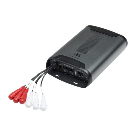
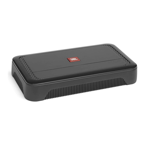
  9. Harman JBL GX-A422SI User manual

Harman JBL GX-A422SI User manual

Service Manual
GX-A422SI
Power Amplifier
Released Global Quality 2015 Harman Consumer Group, Inc. Rev 1.0, 03/2015
8500 Balboa Boulevard
Northridge, California 91329
OWNER’S MANUAL 2
SCHEMATICS DIAGRAMS 18
LAYOUT DIAGRAMS 22
SET BLOCK DIAGRAM 16 PACKAGING INSTRUCTIONS 27
CONTENTS
SET WIRING DIAGRAM 17 MECHANICAL EXPLODED VIEW 26
GX-A422SI
power amplifier
OWNER'S MANUAL
2
2
INTRODUCTION
THANK YOU for purchasing a JBL®GX-A422SI amplifier. So we can better serve you should you require warranty service, please retain your original
sales receipt and register your amplifier online at www.jbl.com.
INCLUDED ITEMS
GX-A422SI Amplifier (x 1) Speaker-level input harness
LOCATION AND MOUNTING
Although these instructions explain how to install the GX-A422SI in a general sense, they do not show specific installation methods that may be
required for your particular vehicle. If you do not have the necessary tools or experience, do not attempt the installation yourself. Instead, please ask
your authorized JBL car audio dealer about professional installation.
INSTALLATION WARNINGS AND TIPS
IMPORTANT: Disconnect the vehicle’s negative (–) battery terminal before beginning the installation.
• Always wear protective eyewear when using tools.
• Check clearances on both sides of a planned mounting surface. Be sure that screws or wires will not puncture brake lines, fuel lines or wiring
harnesses, and that wire routing will not interfere with the safe operation of the vehicle.
• When making electrical connections, make sure they are secure and properly insulated.
• If you must replace any of the amplifier's fuses, be sure to use the same type of fuse and current rating as that of the original.
www.jbl.com
English
3
3
INSTALLATION LOCATION
Amplifiers need air circulation to stay cool. Select a location that provides enough air for the amp to cool itself.
• Suitable locations are under a seat (provided the amplifier doesn’t interfere with the seat adjustment mechanism), in the trunk, or in any other
location that provides enough cooling air.
• Do not mount the amplifier with the heatsink facing downward, as this interferes with the amplifier’s convection cooling.
• Mount the amplifier so that it will not be damaged by the feet of backseat passengers or shifting cargo in the trunk.
• Mount the amplifier so that it remains dry – never mount an amplifier outside the car or in the engine compartment.
MOUNTING THE AMPLIFIER
NOTE : You may find it more convenient to make all of the connections to the amplifier before you permanently mount it to the vehicle.
1. Select a suitable mounting location as described above.
2. Using the amplifier as a template, mark the locations of the mounting holes on the mounting surface.
3. Drill pilot holes in the mounting surface.
4. Attach the amplifier to the mounting surface with four appropriate mounting screws of your own choice. We suggest using #8 Phillips-head sheet
metal screws. Make sure the amplifier is mounted securely.
4
4
POWER AND GROUND CONNECTIONS
IMPORTANT: Disconnect the vehicle's negative (–) battery terminal before beginning the installation.
The GX A422SI amplifier is capable of delivering high power levels, and requires a heavy-duty and reliable connection to the vehicle’s electrical
system to achieve optimal performance. Please adhere to the following instructions carefully.
USING THE CONNECTORS
the GX-A422SI uses the same type of screw terminals for power and speaker connections. This type of terminal is easy to use and allows the easy
connection of large-gauge wire.
To use the connectors, use a Phillips screwdriver to loosen the connector’s set screw, insert the bare wire and tighten the set screw to secure the
wire in the connector, as shown in the illustration below.
Tighten
Screw
Loosen
Screw
Insert Wire
Under Washer
IMPORTANT: Make sure the (+) and (–) speaker bare wires do not touch each other or the other terminal at both the amplifier terminals and speaker
terminals. Touching wires can cause a short circuit that can damage the amplifier.
www.jbl.com
English
5
5
GROUND (GND) CONNECTION
Connect a wire (minimum 10AWG – 5.3mm2)
from the amplifier’s GND terminal directly to a
solid point on the vehicle’s chassis.
• For a good connection, use sandpaper to
clear the paint from the metal surface at this
chassis location. Use a star-type lock washer
to secure the wire’s connection.
POWER (12V) CONNECTION
1. Connect a wire (minimum 10AWG –
5.3mm2) directly to the battery’s positive (+)
terminal.
2. Install a fuse holder for a 20A fuse on this
wire within 18" (46cm) of the battery’s (+)
terminal. Do not install the fuse in the holder
at this time.
3. Route this wire to the amplifier’s location
and connect it to the amplifier’s +12V
terminal. Be sure to use appropriate
grommets whenever routing wires
through the firewall or other sheet metal.
IMPORTANT: Failure to adequately protect
the positive wire from potential damage may
result in a vehicle fire.
4. When you are finished routing and
connecting this wire, install the 20A fuse in
the holder you installed near the battery.
Power
Connectors
Audio System
Head Unit
Chassis Ground
(bare metal)
20A Fuse 18" (46cm)
Remote Turn-On
(optional)
>#18AWG (0.82mm2) Wire
>#10AWG (5.26mm2) Wire
6
6
SPEAKER AND INPUT CONNECTIONS
Always connect the (+) speaker terminal on the amplifier to the (+) terminal on the speaker and the (–) speaker terminal on the amplifier to the (–) terminal
on the speaker.
IMPORTANT: Make sure the (+) and (–) bare wires do not touch each other or the other terminal at both the amplifier terminals and speaker
terminals. Touching wires can cause a short circuit that can damage the amplifier.
SPEAKER CONNECTIONS
Minimum speaker impedance: 2 ohms (each)
Connect the left and right speakers to the L and R (+) and (–) terminals.
Left Speaker Right Speaker
www.jbl.com
English
7
7
INPUT CONNECTIONS
Connect your source unit or processor's line outputs as shown in the illustration below.
L+L–R–R+
Source Unit
Line Outputs
See Set The Crossover Controls, on page 10, for information about setting the amplifier's controls.
USING THE SPEAKER-LEVEL INPUTS
If your source unit doesn't have line-level outputs you can use the included speaker-level input harness to connect
the amplifier to the source unit's speaker outputs. From left to right, the conductors are: L+, L–, R–, R+ (see the
illustration to the right).
8
8
SPEAKER CONNECTIONS: BRIDGED OPERATION
Bridged operation provides a single high-power channel for a subwoofer
Minimum speaker impedance: 4 ohms
Connect the subwoofer to the RL (+) and RR (–) terminals.) NOTE: You can connect two 2-ohm subwoofers in series to maintain the required 4-ohm
impedance for bridged operation.
Subwoofer
www.jbl.com
English
9
9
INPUT CONNECTIONS: BRIDGED OPERATION
Connect your source unit or processor's subwoofer line output to the amplifier's left input, as shown in the illustration below.
NOTE: Use a "Y"-adapter to connect the source unit to the amplifier's left and right input jacks.
L+L–R–R+
Source Unit
"Y"-Adapter Subwoofer
Output
See Set The Crossover Controls, on page 10, for information about setting the amplifier's controls for bridged operation.
To use the speaker-level inputs instead of the line-level inputs, see Using The Speaker-Level Inputs, on page 7.
10
10
CONTROLS, INPUT CONNECTIONS AND INDICATORS
SET THE CROSSOVER CONTROLS
2-CHANNEL OPERATION
Crossover Filter switch:
• If you have connected the amplifier to a pair of 6" or smaller full-range speakers, set the Crossover Filter switch in the “HP” (high-pass) position.
This will limit the amount of low-frequency energy sent to the speakers, significantly reducing distortion and preventing the speakers from damage.
• If you have connected the amplifier to a pair of large full-range speakers (6" x 9" or larger) that can handle significant bass and you are not using a
subwoofer in the system, set the Crossover Filter switch to the "FLAT' (full-range) position.
• If you have connected the amplifier to a pair of woofers or subwoofers, set the Crossover Filter switch in the “LP” (low-pass) position. This will limit
the amount of high-frequency energy sent to the woofers/subwoofers, improving the clarity of vocals and other midrange sounds.
L+L–R–R+
Speaker-Level
Input Connector Protection
Indicator
Line-level
Input Connectors
Crossover
Filter Switch
Bass Boost
Switch
Power
Indicator
Level
Control
www.jbl.com
English
11
11
BRIDGED OPERATION
Crossover Filter switch: When operating the amplifier in bridged mode into a subwoofer, set the Crossover Filter switch in the “LP” (low-pass)
position. This will limit the amount of high-frequency energy sent to the subwoofer.
SET THE INPUT LEVEL
1. Turn all the Level controls on all the system's amplifiers fully counter-clockwise.
2. Play some dynamic music through your source unit and turn its volume up to 3/4 volume.
3. Slowly turn the Level control on the GX-A422SI amplifier clockwise until the music begins to sound distorted.
4. Turn the Level control counter-clockwise slightly until the music no longer sounds distorted.
5. If you're using more than one amplifier, repeat Steps 3 – 4 for all remaining amplifier Level controls.
SET THE BASS BOOST
When you’re using the amplifier in bridged mode to power a subwoofer, the Bass Boost switch can provide 12dB of bass boost at 45Hz. (Set this
switch according to your personal taste, but if using it causes audible distortion or bottoming of your subwoofer we recommend setting it to "OFF."
CAUTION: Only use the Bass Boost switch if you're using the amplifier to power a subwoofer. Using the Bass Boost switch with full-range speakers
can damage the speakers.
POWER AND PROTECTION INDICATORS
POWER INDICATOR
• LED Illuminates orange: Normal operation (power is on).
• LED is off: Amplifier is in standby mode.
PROTECTION INDICATOR
The amplifier's Protection LED should remain off during normal operation. If there is no sound from the amplifier and the Protection LED illuminates
red, see Troubleshooting, on page 12.
12
12
TROUBLESHOOTING
If your amplifier isn't performing the way you think is should, check to see if the problem is covered in this section before calling your dealer or
contacting JBL customer service.
PROBLEM CAUSES AND SOLUTIONS
No sound (the amplifier's Power LED is off) • Check that the amplifier's +12V and GND connections have been properly made.
• Check if the fuse on the +12V wire located near the battery is blown: If so, replace it with an
identical fuse.
• Check all amplifier fuses; if any are blown, replace them with identical fuses.
• If you are using the amplifier's REM connection for turn-on, check that the wire is properly
connected to the audio system's remote turn-on wire or to the vehicle's ACC power terminal.
No sound (the amplifier's Power LED is orange) • Check that all amplifier input and speaker connections have been properly made.
• Check that the amplifier's Level controls are not turned all the way down (counter-clockwise).
• Check that the vehicle audio system's source unit's volume control is not turned all the way
down.
No sound (the amplifier's Protection LED is red) • Confirm that the vehicle's electrical system is supplying between 9V and 16V DC to the
amplifier. If the supply voltage is outside of this range, correct the condition before attempting
to use the amplifier.
• If the amplifier has overheated, wait until it has cooled down before attempting to use it again.
• Disconnect all speakers from the amplifier and attempt to turn it on again:
– If the amplifier turns on (the Power LED is orange), there is a short circuit in one or more of
the speaker wires. Correct all short circuits before reconnecting the speakers to the amplifier.
– If the amplifier does not turn on (the Protection LED is still red and the Power LED is off),
contact your authorized JBL dealer for assistance.
www.jbl.com
English
13
13
PROBLEM CAUSES AND SOLUTIONS
Sound only comes from some of the speakers
connected to the amplifier
• Check that the vehicle audio system's source unit's balance and fader controls are set to their
center (midpoint) positions.
Sound is too quiet, even with the vehicle audio
system's source unit volume all the way up
• Check that the amplifier's Level controls are not turned too low. See Set The Input Level, on
page 11, for information about setting the Level controls.
Sound in the subwoofer is distorted • Set the Bass Boost switch to "OFF."
• Check that the distortion is not originating from the vehicle audio system's source unit.
14
14
SPECIFICATIONS
GX-A422SI
Peak power 600W
Rated power output @ 4 ohms 40W x 2
Bridged power output (4 ohms, 1% THD) 110W x 1
THD+N at rated power <1%
Signal-to-noise ratio (rated output @ 4 ohms) >93dB
Effective damping factor (4 ohms) >50
Frequency response (±1dB) 20Hz – 20kHz ±1dB
Maximum input voltage 20V
Maximum input sensitivity 200mV
Fuse size 20 A
Dimensions (H x W x D) 2" x 8-1/8" x 6-13/16" (51mm x 206mm x 173mm)
Weight 3.1 lb (1.4kg)
1234
power supply
1
2
3
GROUND
REM
+12V
bass boost
45Hz 0-12dB
power
P1
A5
FUSE
P2
HI-IN auto ON
A1
A2
PRT
INPUT SENS
0.2V-4V
A1
A2
A3 A4
LP
FLAT
A6 L -out
2Ω/4Ω
L input
Class AB Audio Power Amplifier
input selector
variable crossover
1
2
3
4
HI IN
Pitch 2.5mm
A
bass boost
45Hz 0-12dB
B5
INPUT SENS
0.2V-4V
crossover
80Hz 12dB/ oct
B1
B2
B3
HP/LP pass
B4
LP
FLAT
B6 4R +out
2Ω/4Ω
R input
Class AB Audio Power Amplifier
input selector
variable crossover
A
A1
A2
32
1
4
A
7 6
5
8
B
HP
HP
10Hz 80Hz >40KHz
crossover
80Hz 12dB/ oct
HP/LP pass
10Hz 80Hz >40KHz
SET BLOCK DIAGRAM
1.GX-A422SI (4Ω2Ω)
)
2 channel or
R5A 10K
R2A
10K
C8A
100P
C4A
10U/16V
R1A
22K C6A
10P
R4A
10K
C7A
100P
C2A
NP100U/25V
R3A
10K
C3A
10U/16V
R16A
1.1K
C5A
10U/16V
C25A
100P
R7A
1.6K
R6A
5.6K
L
C9A
10U/16V
C11A 473
C23A
183
R12A
75K
R10A
75K
R13A
220R
12 R14A
220R
R19A
22K
C24A
471
R28A
1K
R5B 10K
R2B
10K
C8B
100P
C4B
10U/16V
R1B
22K C6B
10P
R4B
10K
C7B
100P
C2B
NP100U/25V
R3B
10K
C3B
10U/16V
R16B
1.1K
C5B
10U/16V
C25B
100P
R7D
1.6K
R6B
5.6K
R
C9B
10U/16V
R28B
1K
6
57
U1B
NJM4560
+15V
-15V
2
31
84
U1A
NJM4560
2
31
8 4
U2A
NJM4560
+15V
-15V
6
57
U2B
NJM4560
2
31
84
U3A
4560
+15V
-15V
2
31
84
U6A
4560
+15V
6
57
U6B
4560
R26B
4.99K
R27B
10K
-15V
C36B
CL823
R20B
1K
BOOST
BASS
C34B
CL823
R22B
43K
C35B
823
R23B
39K
R21B
43K
54
6
SW3B
SW2P2T
R24B
10K
R25B
10K
C36A
823
R20A
1K
C34A
823
R22A
43K
C35A
823
R23A
39K
R21A
43K
R24A
10K
R25A
10K
0dB
12dB
6
57
U5B
4560
23
1
SW3A
SW2P2T
2
3
1
4
SW2A
SW2P3T
C11C
CL333 C23C
CL333 R17A
82K
R29A
43K
R18A
220R
R15A
220R
FL HI 80Hz
-15V
+15V
FL1 LP 180Hz
FL LP 80Hz
FL FULL
C11B
CL473
C23B
CL183
R12B
75K
R10B
75K
R13B
220R
R14B
220R
R19B
22K
C24B
CC471
2
31
8 4
U5A
4560
67
5
8
SW2B
SW2P3T
C11D
CL333 C23D
CL333 R17B
82K
R29B
43K
R18B
220R
6
57
U4B
4560
R15B
220R
FL HI 80Hz
LP 80Hz
FL LP 80Hz
FL FULL
6
57
U3B
4560
2
31
84
U4A
4560
+15V
-15V
-15V
+15V
C14A
104 C15H
104
1
2
3
4
5
6
7
8
9
CN1A
CN9
SP REM
LED-PRO
CH2OUT
CH1OUT
4
5
6
VR2B
B20K
1
2
3
VR2A
B20K
12
ESD1
NC
12
ESD2
NC
12
ESD3
NC
1 2
ESD4
NC
R9H
18K
R3H
18K
R7H
5.6K
R8H
18K
R4H
5.6K
R5H
18K
R6H
2.2K
R2H
2.2K
HAR+
C5H
106
C2H
106 R9
47K
R8
47K
R10
47K R11
47K
1
2
3
4
CON1
4P
LED2
POWER
LED1
PROT
R27A
4.7K
+15V
R1S
56K C1S
104P
RCA-PRO
R2S
56K C2S
104P
RCA-PRO
RCA-PRO
R1
1K C1
105
C4H 106
C3H 106
C7H 106
C6H 106
R4
4.7K
R5
10K
R6
10K
BOOST
BASS
0dB
12dB
D1
1N4148
1
2
3
4
SP REM
HAL+
HAL-
HAR-
HAR+
-15V
C3
104P
+15V
C5
681(NC)
C6
681(NC)
J16
12.5 J17
12.5 J18
12.5 J21
12.5 J11
7.5 J24
6
R5z 5.1K
C8z
100P
C6z
10P
R4z
5.1K
C7z
100P
R6z
8.2K
6
57
U7B
NJM4560
+15V
-15V
R5s
5.1K C8s
100P
C6s
10P
R4s
5.1K
C7s
100P
R6s
8.2K
2
31
84
U7A
NJM4560
J14
12.5 J15
12.5
+15V
+15V
-15V
-15V
J23
7.5 J2
7.5
J5
7.5
J20
7.5
J22
12.5 J19
12.5
J10
7.5
J9
7.5
J6
7.5
J7
10
J8
10
J12
10 J13
10
J26
0R
C2
10
C4
10
J3
0R
J4
0R J25
0R
R2A1
0R R2A2
0R
R1G
4.7K
J27
15
J28
6
SCHEMATICS DIAGRAM - FRONT END BOARD
1234
A
B
C
D
8
7654321
D
C
B
A
C102
102
R169P
22R, 1/3W
33
22
11
CN3
POWER
R157P
2K2
R161P
2K2
PGND
REM
+12V
D31
F16C20
D32
F16A20
Q22
80N70F4
Q26
80N70F4
R160P
47R
R164P
47R
C125P
103
R167P
22R/ 1W
C126
103
R168P
22R/ 1/2W
R69
10K,1/10W
C139
104
C140
104
31 5.5:10.5
R176P
10K,1/3W
R177P
10K,1/3W
C152
CC104
C24
104
P+12V
C119P
104
R155P
1K
R156P
1K
+
1
-
2
FED
3
DT
4
CT
5
RT
6
GND
7
OP1
8E1 9
E2 10
OP2 11
VCC 12
13
REF 14
-15
+16
U18 TL494
R154P
100K
R175P
20K
C143P
102
C117P
104
C132P
104
R36
10K
R19P
47K
R132P
2K2
R102
4K3 C9P
104 R33P
91K
2R1
6K8
C1P
CC104
C21
100uF/25V
C151
22uF/50V
REM
R83P
100K
R70P
1K
1 2
F1A
20A
C24P
104
+BATT
CA2P
104
CA124P
100uF/16V
CA123P
100uF/16V
R111P
22R/1W
R126P
22R/1W
CA1P
104
R8
3K3
R7
3K3
C9
22uF/50V
C11
22uF/50V
1 2
L6
2.5MH
R178P
3K3
R179P
3K3
C20
104
C19
104
C145
1000U/35V
C146
1000U/35V
CA125P
104
C10P
104
3
4
8
6
5
1
2 7
T1
LED-PRO
C92
222
1
2
3
4
5
6
7
8
9
CN1B
CN9
C401 102
C402 102
C403 102
C404 102
C26
CL104
12
3 4
U1P
PC817
Q8
2SC1815
R9P
10K R10P
220K
R11P
10K
R33
1M
C59
4.7uF/50V
2
31
8 4
U2PA
4560 6
57
U2PB
4560
R40
4.7R
R39
10K
R38
4.7R
R37
10K
C60
104P
R16P
2.2K
RB6
13K
R171P
12K
C82
47uF/25V
C79
104
R20P
47K
R138P
2K C81
104
C84
104
C124P
104
R200P
2K
R46
220R
RB4
22K
R61P
100K
R149P
10K
RB5
10K
R2P
4.99K R35
10K
RB3
4.02K
D1
1N4148
2.5
Hi16.5
D11P
1N4148
R34P
10K
+VCC
-VCC
+15V
-15V
LED-PRO
-15V
+15V
+15V
-15V
+15V
RCA-PRO
Q201P
SMD,BCX55
Q202P
SMD,BCX52
D38
IN4148 D18
IN4148
D19
IN4148
Q33
2SC1815
Q17
SMD,BCX52
Q32A
2SC1815
Q32
2SA1015
Q19
2SA1015
Q20
2SA1015
Q7
2SC1815
DZ102P
15V
DZ103P
15V
D15
IN4007
C3S
100uF/25v
R4S
4.7K
Q1S
1815
Q2S
1815
R3S
10K RCA-PRO
D1S
1N4148
PROT
C124
104
D39
3.9V
+5V
LP 8.5
C111
W1500/25V
J2
10mm J3
10mm J4
10mm
A1
P1
3.5
A1
P2
3.5
A1
P3
3.5
J5
10mm
J6
5mm
J7
15mm
J8
20mm
J9
15mm
J10
5mm
PROT
C125
104
J12
7.5mm
J13
7.5mm
J14
20mm
J15
20mm
J17
10mm J19
10mm
J26
7.5mm
J27
7.5mm
J25
7.5mm
J11 20mm
J30
10mm
J42
20mm
J41
6mm
J43
15mm
J44
15mm
J45
6mm
J46
15mm
J47
20mm
J16
10mm
J48
5mm
J49
20mm
J50
20mm
R41
0R
R42
0R
R43
0R
R44
0R
12
R45
0R
J51
10mm
1 2
J52
10mm R
L
-AMP
+AMP1
-AMP1
J69 10mm
J71
15mm
J73
15mm
J72
15mm
J70
15mm
Auto
Auto
RB7
0R
+AMP
R241
0R
J76
10mm
D16
IN4007
D17
IN4007
J1 30mm
J79
5mm
DZ102P1
15V
R161
0R
R162
0R
C127UH(NC)
C13
7UH(NC)
-25V
SCHEMATICS DIAGRAM - MAIN BOARD - POWER PART
R131
2K
R144
1K
C137
47uF/25V
Q103
2SC1815
R135
47R
R139
6K8
R134
47R
Q102
2SC1815
Q105
2SC1015 Q104
2SC1015
R137
47R
R136
47R
R138
6K8
Q109
667
Q108
MPSA13
C135
CM104
R147
3K3
R148
5K6
Q106
2N5401
Q107
2N5551
C131
100P
R146
47R
R149
47R
C132
100P
R165
0.15/5W
R156
680R
D101
IN4148
R159
6K8
Q113
2SC1815
C136
104
Q110
647
R155
0.15/5W
R157
680R
D102
IN4148
R160
6K8
R158
4R7/1W
C158
104
C133
47P
R145
11K
R151
220R/0.5W
+VCC
R170
1K
R168
10K
R169
1K
R175
33K
R166
3K
R231
2K
R244
1K
C237
47uF/25V
Q203
2SC1815
R235
47R
R239
6K8
R234
47R
Q202
2SC1815
Q205
2SC1015 Q204
2SC1015
R237
47R
R236
47R
R238
6K8
Q209
667
Q208
MPSA13 C235
CL104
R247
3K3
R248
5K6
Q206
2N5401
Q207
2N5551
C231
100P
R246
47R
R249
47R
C232
100P
R265
0.15/5W
R256
680R
D201
IN4148
R259
6K8
Q213
2SC1815
C236
104
Q210
647
R255
0.15/5W
R257
680R
D202
IN4148
R260
6K8
R258
4R7/1W
C258
104
C233
47P
1 2
R245
11K
R251
220R/0.5W
+VCC
-VCC
R270
1K
R268
10K
R269
1K
R275
33K R266
3K
LCH
RCH
R133
33K
R233
33K
-VCC
Q111
718
Q211
718
Q212
688
Q112
688
Q102P
STN3904S
Q103P
STN3904S
R158P
6K8
C142P
100uF/25V
D101P
IN4148
1
2
3
4
JK1
REAR
R132
56K
R232
56K
C192B
CW 10u/50V
C192A
CW 10u/50V
R140
220R/0.5W
R240
220R/0.5W
C17
CL224 C18
CL224
R24
51K
C22
220U/16V
R30
6K8
D25
1N4148
Q17A
2SC1815
Q16
2SC1815
D9
1N4148 R23A
51K
RCH
LCH
C300
100p
C301
100P
C302
100P
C303
100P
D203
IN4148
D103
IN4148
C2
122
C3
122
R3B PTC NC
R3A PTC NC
R4B
270R
R4A
270R
152改为122
152改为122
R31
6K2
PROT
J24
20mm
PROT
J21
20mm
J20
20mm
J23
20mm
J22
20mm
J28
10mm
J29
10mm
PROT
J31
10mm
J32
10mm
J33
12mm
PROT
J34
15mm
PROT
C142P1
100uF/25V
J35
6mm
J36
6mm
J37
10mm
J38
10mm
J39
7.5mm
J40
6mm
R
L
J53
6mm
J54
10mm
-AMP1
-AMP
+AMP
+AMP1
J55
10mm
J56
10mm
J57
10mm
J58
10mm
J59
20mm
J61
15mm
J60
15mm
J62
12mm
J65
10mm
J64
10mm
J63
15mm
J66
6mm
J67
7.5mm
J74
12mm
J75
7.5mm
J77
12mm
J78
7.5mm
PROT
C23
CL222(NC) C25
CL222(NC)
J80
7.5mm
SCHEMATICS DIAGRAM - MAIN BOARD - AMPLIFIER PART

Other Harman Amplifier manuals

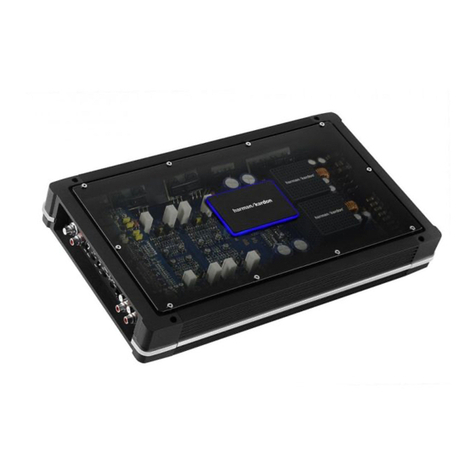
Harman AXYS PB-400 Instruction Manual

Harman

Harman AXYS PB-400 Instruction Manual

Harman JBL Club A600 User manual

Harman

Harman JBL Club A600 User manual

Harman JBL Club A754 User manual

Harman

Harman JBL Club A754 User manual

Harman Infinity 3004A User manual

Harman

Harman Infinity 3004A User manual

Harman JBL SYNTHESIS SDA8300 Instruction Manual

Harman

Harman JBL SYNTHESIS SDA8300 Instruction Manual

Harman DBX 500 Series User manual

Harman

Harman DBX 500 Series User manual

Harman JBL CSA-2120 User manual

Harman

Harman JBL CSA-2120 User manual

Harman JBL GTO7520 User manual

Harman

Harman JBL GTO7520 User manual

Harman AXYS Dante OCTADRIVE DSP-DN User manual

Harman

Harman AXYS Dante OCTADRIVE DSP-DN User manual

Harman JBL PARTYBOX710 User manual

Harman

Harman JBL PARTYBOX710 User manual

Harman crown DSi Series User manual

Harman

Harman crown DSi Series User manual

Harman JBL Club A754 User manual

Harman

Harman JBL Club A754 User manual

Harman infinity KAPPA five User manual

Harman

Harman infinity KAPPA five User manual

Harman CROWN CT16S User manual

Harman

Harman CROWN CT16S User manual

Harman Ininity INFDSP4425 User manual

Harman

Harman Ininity INFDSP4425 User manual

Harman Crown DriveCore Install DA Series User manual

Harman

Harman Crown DriveCore Install DA Series User manual

Harman JBL DSP4086 User manual

Harman

Harman JBL DSP4086 User manual

Harman JBL Commercial VMA Series User manual

Harman

Harman JBL Commercial VMA Series User manual

Harman Crown CDi 6000 User manual

Harman

Harman Crown CDi 6000 User manual

Harman JBL GTO-1001EZ User manual

Harman

Harman JBL GTO-1001EZ User manual

Harman JBL CSA 140Z User manual

Harman

Harman JBL CSA 140Z User manual

Harman dbx 676 User manual

Harman

Harman dbx 676 User manual

Harman JBL Apex PA454 User manual

Harman

Harman JBL Apex PA454 User manual

Harman JBL GTO-751EZ User manual

Harman

Harman JBL GTO-751EZ User manual

Popular Amplifier manuals by other brands

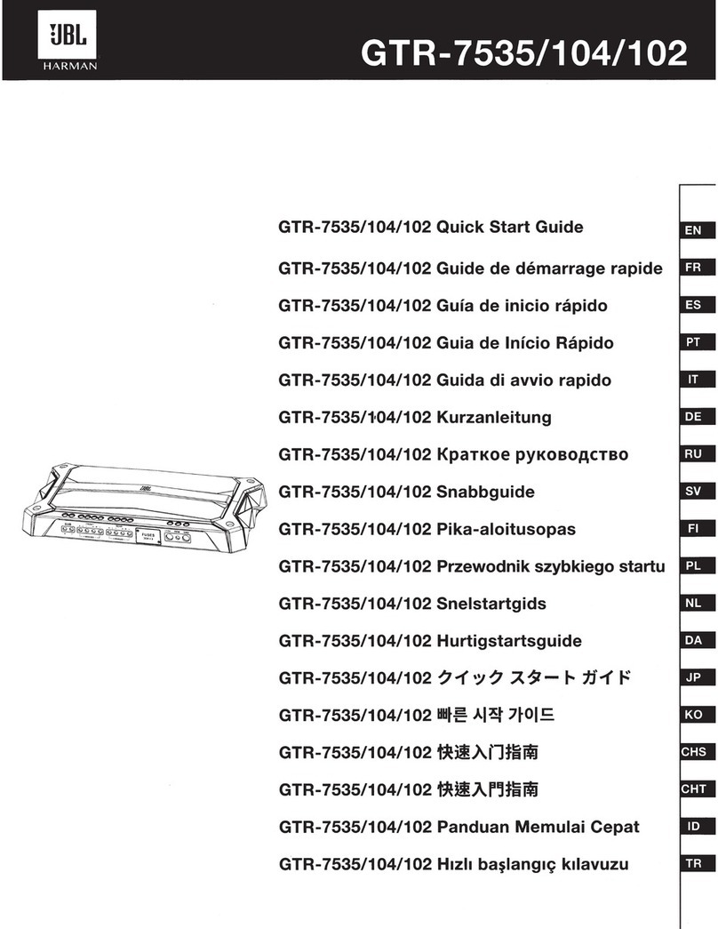
JBL SYNTHESIS SDA-7200 operating manual

JBL

JBL SYNTHESIS SDA-7200 operating manual

Suhr DUAL BOOST user guide

Suhr

Suhr DUAL BOOST user guide

Yamaha A-S501 Service manual

Yamaha

Yamaha A-S501 Service manual

Crown XLS-402TX datasheet

Crown

Crown XLS-402TX datasheet

Technics SU-A700 operating instructions

Technics

Technics SU-A700 operating instructions

Sherwood AX-5505 operating instructions

Sherwood

Sherwood AX-5505 operating instructions

Adcom GTP-400 owner's manual

Adcom

Adcom GTP-400 owner's manual

JDS Labs The Element operating instructions

JDS Labs

JDS Labs The Element operating instructions

HELIX DARK BLUE instruction manual

HELIX

HELIX DARK BLUE instruction manual

Lindell 6X-500 user manual

Lindell

Lindell 6X-500 user manual

ISOMET RFA1170-4+iMS4-L instruction manual

ISOMET

ISOMET RFA1170-4+iMS4-L instruction manual

Atec CMX25 Operating and maintenance instructions

Atec

Atec CMX25 Operating and maintenance instructions

NAD PP 2e user guide

NAD

NAD PP 2e user guide

Master audio HD800 user manual

Master audio

Master audio HD800 user manual

Wadax Pre One Ultimate Trio user manual

Wadax

Wadax Pre One Ultimate Trio user manual

VocoPro DA-3808 PRO owner's manual

VocoPro

VocoPro DA-3808 PRO owner's manual

Anacon TUBEWONDER user manual

Anacon

Anacon TUBEWONDER user manual

Panduit Atlona AT-UHD-CAT-4 manual

Panduit

Panduit Atlona AT-UHD-CAT-4 manual

manuals.online logo
manuals.online logoBrands
  • About & Mission
  • Contact us
  • Privacy Policy
  • Terms and Conditions

Copyright 2025 Manuals.Online. All Rights Reserved.