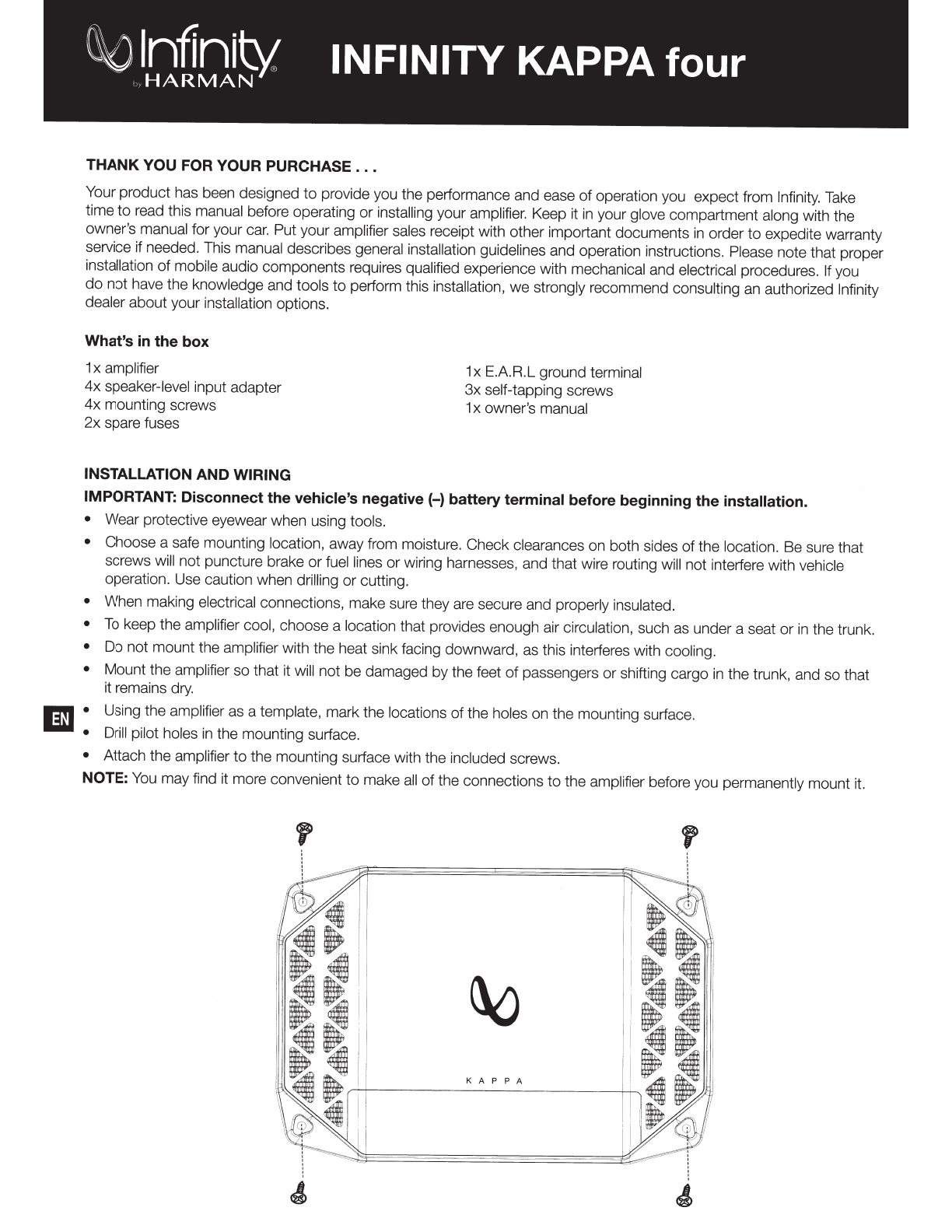
Harman INFINITY KAPPA four User manual

Infinity
Kappa
four
-
Owner's
Manual
IBII
Infinity
Kappa
four
-
Mode
D'emploi
Iiiii
Infinity
Kappa
four
-
Manual
de
Propietario
D
Infinity
Kappa
four
-
Manual
do
Proprietario
Ill
Infinity
Kappa
four
-
A~~
X~
~
~A1
-
Infinity
Kappa
four-
JJ.IPf.M
-
Infinity
Kappa
four- BIJiif.fffi -
Infinity
Kappa
four
-
Panduan
Pengguna
•

~
lnffnit-'1
INFINITY KAPPA four
~
HARMAN
THANK YOU FOR YOUR PURCHASE
...
Your product has been designed
to
provide you the performance and ease
of
operation you expect from Infinity. Take
time
to
read this manual before operating
or
installing your amplifier. Keep it
in
your glove compartment along with the
owner's manual for your
car.
Put your amplifier sales receipt with other important documents
in
order
to
expedite warranty
service if needed. This manual describes general installation guidelines and operation instructions. Please note that proper
installation
of
mobile audio components requires qualified experience with mechanical and electrical procedures. If you
do
not have the knowledge and tools
to
perform this installation,
we
strongly recommend consulting an authorized Infinity
dealer about your installation options.
What's
in
the
box
1x amplifier
4x
speaker-level input adapter
4x
mounting screws
2x
spare fuses
INSTALLATION AND WIRING
1x E.A.R.L ground terminal
3x
self-tapping screws
1x owner's manual
IMPORTANT: Disconnect the vehicle's negative (-) battery terminal before beginning the installation.
• Wear protective eyewear when using tools.
• Choose a safe mounting location, away from moisture. Check clearances on both sides
of
the location. Be sure that
screws will
not
puncture brake
or
fuel lines or wiring harnesses, and that wire routing will not interfere with vehicle
operation. Use caution when drilling or cutting.
• When making electrical connections, make sure they are secure and properly insulated.
•
To
keep the amplifier cool, choose a location that provides enough air circulation, such as under a seat or
in
the trunk.
•
Do
not mount the amplifier with the heat sink facing downward, as this interferes with cooling.
• Mount the amplifier so that it will not be damaged by the feet
of
passengers
or
shifting cargo
in
the trunk, and so that
it remains dry.
E • Using the amplifier as a template, mark the locations of the holes on the mounting surface.
•
Drill
pilot holes
in
the mounting surface.
• Attach the amplifier
to
the mounting surface with the included screws.
NOTE:
You
may find it more convenient
to
make all
of
the connections
to
the amplifier before you permanently mount it.
K A P P A

0
Speaker
Output Connectors
Connect
speakers
to
these terminals, observing
proper
polarity (connect each speaker's positive(+) lead
to
the
appropriate positive(+) terminal, and negative(-) lead
to
the
appropriate negative(-) terminal.
4-channel operation:
Connect
the
front left and right
speakers
to
the
front L+, L-, R+, and R- terminals, and
the
rear left and right speakers
to
the
rear L+, L-, R+,
and R- terminals.
3-channel operation:
Connect
the
stereo speakers
to
the
front L+, L-, R+, and R terminals, as described above.
Connect
the
single speaker's + lead
to
the rear L+ termi-
nal, and
the-
lead
to
the
rear R- terminal.
2-channel (bridged) operation:
Connect
one speaker's
+lead
to
the front
L+
terminal, and
the-
lead
to
the front
R- terminal.
Connect
the
other speaker's + lead
to
the
rear L+ terminal, and
the-
lead
to
the rear R- terminal.
NOTE:
Minimum speaker impedance
is
2 ohms.
f)
Fuses
Replace fuses only with
the
same amperage: 30A.
E)
Power
Input Connectors
• Power:
Run
4-gauge
power
wire from the
+12V
input
to
the positive terminal
of
the
vehicle's battery. Insert
bare wire into the terminal on the amplifier, then tighten
the setscrew with a Phillips screwdriver.
• Install an appropriate fuse holder and 1
OOA
fuse within
18" (457mm)
of
the
battery. Install protective grommets
when routing wires through the bulkhead or other sheet
metal. Use larger-gauge wiring for longer runs.
+
12
volt
Remote
Ground
t t t
o o
To
in-dash
receiver
_j
ggg
gc
)8811----------·•
~0
0
000000
0 0
T
Power
wire
18" (46cm)
f'
,.-!?-------';?--,
l_
Vehicle
battery
Ground
wire
• Ground:
Run a wire (the same gauge as the
power
wire) from the
GND
input
to
a factory bolt
in
the
vehicle's chassis (see illustration below).
NOTE:
Remove any paint from
the
chassis for best contact. If
using a ring connector, place a star washer below
the
ring
connector
for a secure connection.
• For a
more
secure ground connection, use
the
included E.A.R.L. ground terminal. Crimp
the
open
end
of
the terminal
to
the
end
of
your ground wire,
then place the terminal against bare chassis metal,
and secure with
the
included self-tapping screws.
NOTE: Be sure
to
check
below
your
desired ground
location
to
ensure that
the
screws will
not
puncture
brake lines, fuel lines,
or
wiring harnesses.
Factory
Bo~
Note:
Remove
any
paint
below
ring
connector
Ring
Connector
Star
Washer
Ground
Wire
\
OR
ID

0 Preamp outputs
The
Kappa four amplifier allows
you
to send a second
amplifier line-level
signal.
Connect a set of
RCA
patch cables
to the line-level inputs
on
the Kappa amplifier at one
end
,
and to the second amplifier's line-lev
el
inputs at the other.
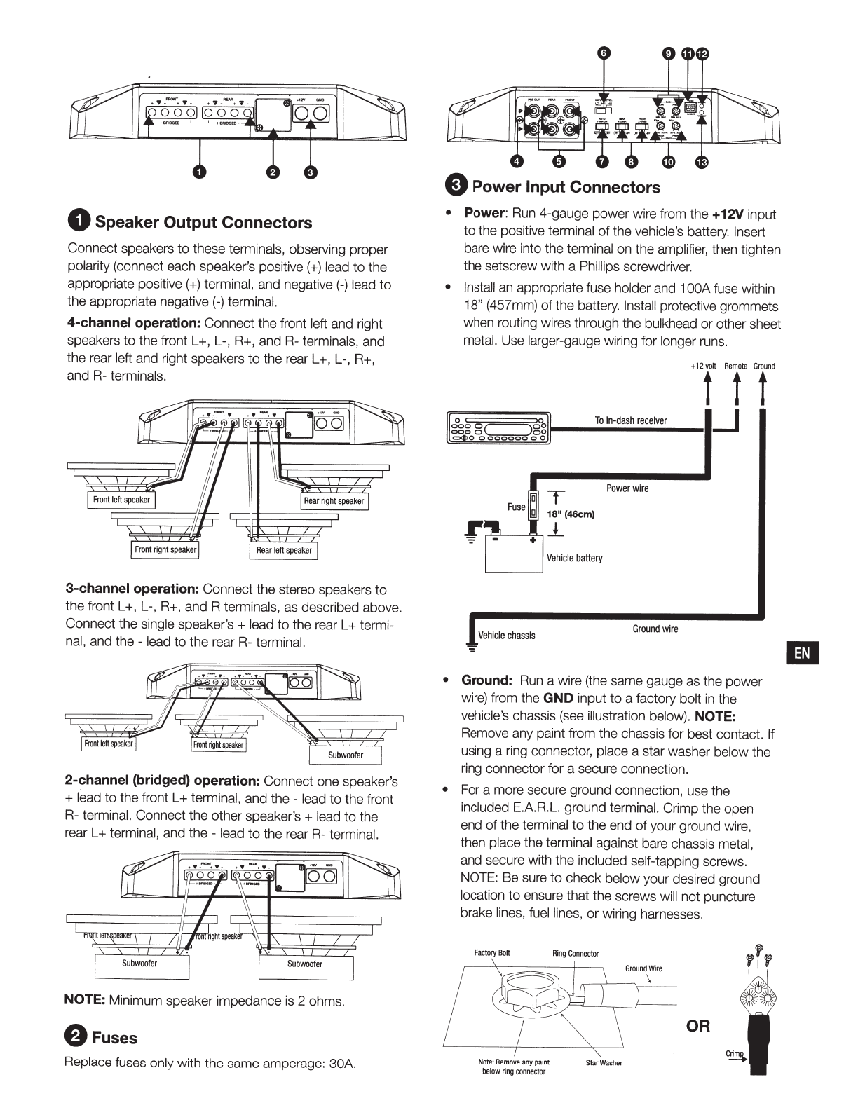
0 Line-level inputs (RCA)
If
your source unit offers preamp outputs, connect
to
the
front and rear
Land
R,
and subwoofer inputs using RCA
patch cables.
@
··
----
.....
1---
~oo--
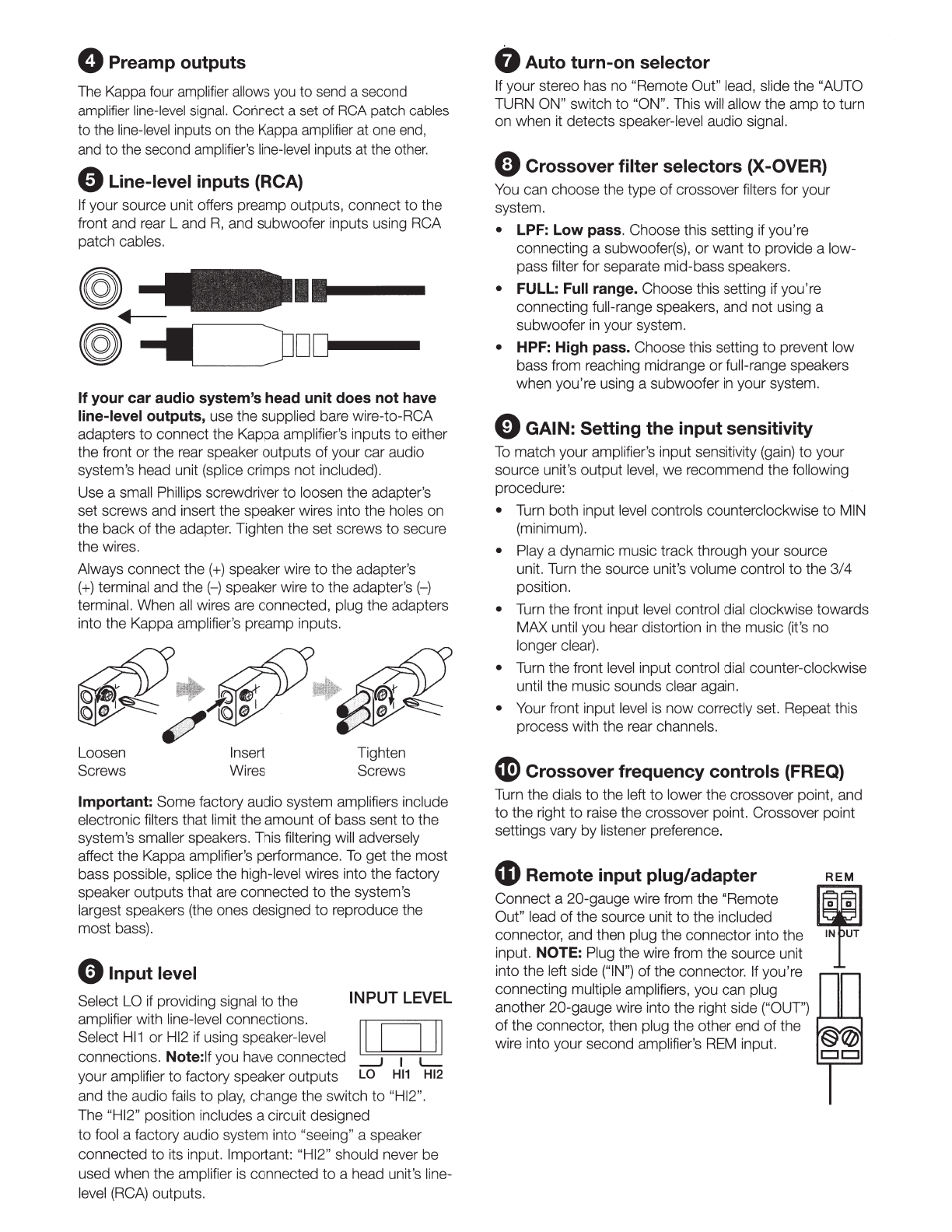
Ifyour car audio system's head unit does not have
line-level outputs, use the supplied bare wire-to-RCA
adapters
to
connect the Kappa amplifier's inputs
to
either
the front or the rear speaker outputs
of
your car audio
system's head unit (splice crimps not included}.
Use a small Phillips screwdriver
to
loosen the adapter's
set screws and insert the speaker wires into the holes on
the back of the adapter. Tighten the set screws
to
secure
the wires.
Always connect the(+) speaker wire
to
the adapter's
(+)terminal and
the(-)
speaker wire
to
the adapter's (-)
terminal. When
all
wires are connected, plug the adapters
into the Kappa amplifier's preamp inputs.
~
.
#
.
~~~~
'
Loosen Insert
Screws Wires Tighten
Screws
Important: Some factory audio system amplifiers include
electronic filters that limit the amount
of
bass sent
to
the
system's smaller speakers. This filtering will adversely
affect the Kappa amplifier's performance.
To
get the most
bass possible, splice the high-level wires into the factory
speaker outputs that are connected
to
the system's
largest speakers (the ones designed
to
reproduce the
most bass).
eInput level
Select LO if providing signal to the INPUT
LEVEL
amplifier with line-level connections.
II
n
II
Select
Hl1
or
Hl2 if using speaker-level .. _ ..
connections. Note:
If
you have connected
__J
1
L--
your amplifier
to
factory speaker outputs
LO
Hl1
Hl2
and the audio fails to
play,
change the switch
to
"HI2".
The "HI2" position includes a circuit designed
to
fool a factory audio system into "seeing" a speaker
connected
to
its input. Important: "HI2" should never be
used when the amplifier
is
connected
to
a head unit's line-
level
(RCA)
outputs.
t)
Auto turn-on selector
If
your stereo has no "Remote Out" lead, slide the "AUTO
TURN ON" switch to "ON". This will allow the amp
to
turn
on when it detects speaker-level audio signal.
C)
Crossover filter selectors (X-OVER)
You
can choose the type of crossover filters for your
system.
• LPF: Low pass. Choose this setting if you're
connecting a subwoofer(s), or want
to
provide a low-
pass filter for separate mid-bass speakers.
• FULL: Full range. Choose this setting if you'
re
connecting full-range speakers, and not using a
subwoofer
in
your system.
• HPF: High pass. Choose this setting
to
prevent low
bass from reaching midrange
or
full-range speakers
when you'
re
using a subwoofer
in
your system.
E)GAIN: Setting the input sensitivity
To
match your amplifier's input sensitivity (gain)
to
your
source unit's output level,
we
recommend the following
procedure:
• Turn both input level controls counterclockwise to MIN
(minimum).
• Play a dynamic music track through your source
unit. Turn the source unit's volume control
to
the 3/4
position.
• Turn the front input level control dial clockwise towards
MAX until you hear distortion
in
the music (it's no
longer clear).
• Turn the front
level
input control dial counter-clockwise
until the music sounds clear again.
• Your front input level
is
now correctly set. Repeat this
process with the rear channels.
G)
Crossover frequency controls (FREQ)
Turn the dials
to
the left
to
lower the crossover point, and
to
the right
to
raise the crossover point. Crossover point
settings vary by listener preference.
4D
Remote input plug/adapter
Connect a 20-gauge wire from the "Remote
Out" lead
of
the source unit
to
the included
connector, and then plug the connector into the
input. NOTE: Plug the wire from the source unit
into the left side ("
IN")
of the connector.
If
you'
re
connecting multiple amplifiers, you can plug
another 20-gauge wire into the right side ("OUT")
of
the connector, then plug the other end
of
the
wire into your second amplifier's
REM
input.
REM
g)
IN1UT

4&
&
4e
Power/Protect indicators
The power light will illuminate when the
amplifier
is
getting power and playing. Q POWER
The protect indicator will illuminate
in
the
event
of
conditions such as over/under Q
voltage, short circuit, amplifier output PROTECT
circuit failure, or excessive heat.
SPECIFICATIONS
• Operating voltage:
9-16
volts
• RMS power @4 ohms: 1
OOW
x 4
• RMS power @2 ohms:
120W
x 4
• RMS bridged power @4 ohms: 240W x 2
• Total peak power:
1500W
• Frequency response: 15Hz -35KHz@-3dB
• Crossover filter: LPF/HPF
32Hz-
320Hz
Variable 12dB/Oct
• High input maximum signal level: 20V
• High input maximum sensitivity: 2V
• Line input maximum signal level: 2V
• Line input maximum sensitivity: 0.2V
• Line-in signal-to-noise ratio (reference to 1' watt):
~80dB
• Quiescent current
draw
:
:::;1.6A
• THD
+Nat
rated power:
:::;0.1%
• Fuse size: 2 x 30A
• Dimensions
(H
x W x
D)
: 43.00mm x 177
.OOmm
x
260mm
• Weight: 2.57kg
~
HARMAN
~
HARMAN International Industries,
Incorporated 8500 Balboa Boulevard,
Northridge, CA 91329 USA
www.infinityspeakers.com
TROUBLESHOOTING
PROBLEM: No audio and POWER INDICATOR
is
off.
CAUSE and SOLUTION: No voltage at
BATI
+ and/or
REM
terminals, or bad
or
no ground connection. Check
voltages at amplifier terminals with VOM.
PROBLEM: No audio and PROTECT INDICATOR flashes
every 4 seconds.
CAUSE and SOLUTION: DC voltage
on
amplifier output.
Amplifier may need service; see enclosed warranty card
for service information.
PROBLEM: No audio and PROTECT and POWER
INDICATORS flash.
CAUSE and SOLUTION: Voltage less than 9V on
BATI
+
connection. Check vehicle charging system.
PROBLEM: No audio and PROTECT INDICATOR
is
on.
CAUSE and SOLUTION: Amplifier
is
overheated. Make
sure amplifier cooling
is
not blocked at mounting location.
Verify that speaker-system impedance
is
within specified
limits.
Or,
there may be voltage greater than 16V (or less
than 8.
5V)
on
BATI
+ connection. Check vehicle charging
system.
PROBLEM: Amplifier fuse keeps blowing.
CAUSE and SOLUTION: The wiring
is
connected
incorrectly
or
there is a short circuit. Review installation
precautions and procedures. Check wiring connections.
PROBLEM: Distorted audio.
CAUSE and SOLUTION: Gain
is
not set properly. Check
INPUT LEVEL setting. Check speaker wires for shorts
or
grounds. Amplifier or source unit may be defective.
PROBLEM: Distorted audio and PROTECT INDICATOR
flashes.
CAUSE and SOLUTION: Short circuit
in
speaker
or
wire.
Remove speaker leads one at a time to locate shorted
speaker
or
wire, and repair.
PROBLEM: Music lacks dynamics
or
"punch."
CAUSE and SOLUTION: Speakers
are
not connected
properly. Check speaker connections for proper polarity.
PROBLEM: Engine
noise-whining
or
clicking-in
system when the engine
is
on.
CAUSE and SOLUTION: Amplifier
is
picking up
alternator noise. Turn down gain. Move audio cables
away from power wires. Install an alternator noise filter on
power line between battery and alternator. Check ground
connections on the
amplifier-
a loose or improper ground
is
one of the main causes for noise.
© 2018 HARMAN International Industries, Incorporated.
All
rights reserved.
Infinity
is
a trademark of HARMAN International Industries, Incorporated,
registered
in
the United States and/or other countries. Features, specifications
and appearance are subject
to
change without notice.

TR04954_A
Table of contents
Other Harman Car Amplifier manuals
Popular Car Amplifier manuals by other brands

Directed Audio
Directed Audio 600/4 owner's manual

Cerwin-Vega
Cerwin-Vega V250.2 owner's manual

Boss Audio Systems
Boss Audio Systems Diablo D1000.2 user manual

Blaupunkt
Blaupunkt GTA 1350 OPERATING AND INSTALLATION Manual

VVME
VVME MGB2.60 owner's manual

Profile
Profile Baja HA1000 Installation instructions & owner's manual