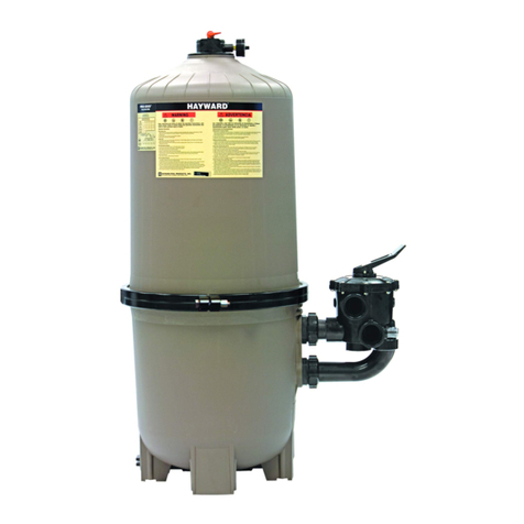
HARMSCO Betterfilter BF144 BKM User manual

HARMSCO®
®
INSTALLATION AND OPERATION MANUAL
UPFLOW SWIMMING POOL CARTRIDGE FILTER
CARTRIDGE CLEANING INSTRUCTIONS
HARMSCO CARTRIDGES
May be cleaned and reused before replacement is necessary.
Cartridge cleaning is necessary only when flow falls below that required or
when pressure increase over start-up pressure exceeds 10 pounds.
INSTRUCTIONS FOR CLEANING CARTRIDGES
See Page 4 on how to remove and replace cartridge(s) for cleaning.
Remove rim gasket to prevent damage during cleaning.
Normal Cleaning Procedure.
Normal cleaning is done by using a pressure nozzle on the end of your garden
hose. Direct jet spray at cartridges on an angle to remove dirt.
Special Cleaning Procedures.
To be used only when normal procedure is insufficient to return cartridge to
normal filter runs.
Removing Oils From Cartridges. If oils coat cartridges and cause reduced flow, this
material may be removed by soaking cartridges in a solution of 2 lb.Tri-sodium Phosphate
to 10 gallons of water or a Tri-sodium Phosphate based product. Usually 12 hours soaking time
will break oil coating from cartridge. Enzyme products are known to release oils from cartridge
media and in some cases may eliminate the need for soaking. Tri-sodium Phosphate and
enzyme products are available at most swimming pool distributors and retail locations. Repeat
Normal Cleaning Procedure.
Removing Algae From Cartridges. If algae coats the cartridges and causes reduced flow,
soak cartridges in a solution of 2 lb.Tri-sodium Phosphate to 10 gallons of water. Add 1 pint
of swimming pool chlorine to kill the algae. Soak for one hour. Check pool chemistry for cause of
algae growth.
Removing Calcium Or Mineral Deposits. ***Caution*** Do not use muriatic acid on
cartridges until all oils have been removed as in step #1 above. Make sure all previously
used products have been thoroughly rinsed from cartridges.
If calcium deposits are present, perform operation #1 above. Rinse - then, in a solution of 1 part
muriatic acid to 20 parts water, soak until bubbling action stops. Use a plastic garbage
container or similar vessel. Check pool chemistry for high PH or Alkalinity. Repeat Normal
Cleaning Procedure.
The only exception to the above procedures are with the use of biguanides (i.e. Baquacil,
SoftSwim or other similar sanitizer). When using a biguanide, always soak the cartridge
with muriatic acid first (as described in #3), and then soak in Tri-sodium Phosphate and water,
(as described in #1).
Heed all manufacturer's posted instructions, warnings and cautions
when using any product.
1
2
3
4

2
TYPICAL INSTALLATION OF RESIDENTIAL POOLS
Where unit is being installed below water
level of the pool, it is necessary to pro-
vide valves as indicated in the drawing
as shown, so that the filter housing may
be opened without draining the pool.
To protect against electrolysis, all
metal components of the water circu-
lation and heating systems must be
connected by a wire to ground the entire
system.
Filter housings must be grounded
DO NOT STORE CHEMICALS NEAR FILTER HOUSING
TYPICAL INSTALLATIONS*
For Residential and Commercial Pools
SUGGESTED INSTALLATION (Fig. 1)
1. Install 1-1/2" "T" on the center nipple as
shown in figure 1.
2. Pipe water from discharge of pump to one
side of this "T".
3. Install a 1-1/2" x approximately 10" nipple
from other side of this "T" with 1-1/2"
valve at end of nipple.This is for draining
filter unit.
4. Install 1-1/2" elbow on the other nipple as
illustrated.This is the return-to-pool line.
SUGGESTED INSTALLATION (Fig. 2)
1. Install 2" thread to socket PVC elbows on
side of nipple marked inlet–Pipe water from
pump discharge to this elbow.
2. Install 2" thread to socket PVC elbow on
center nipple marked outlet.This is the
return to pool line.
3. Install 1" valve or cap on marked drain.
SUGGESTED INSTALLATION (Fig. 3)
1. Install thread to socket "T" on the side
nipple as shown in figure 3. Pipe water from
discharge of pump to one side of this "T".
2. Install nipple and valve in other side of this "T".
This is the drain for emptying filter housing.
3. Install thread to socket PVC elbow on
center outlet.This is the return-to-pool line.
SUGGESTED INSTALLATION (Fig. 4)
1. Install water pipe from the pump to flange
marked "inlet".
2. Pipe return-to-pool line flange marked "outlet".
3. Install valve in drain line to threaded
nipple marked "drain".
FILTER
VALVES
MAIN DRAIN LINE
RETURN TO POOL LINE
CHEMICAL
CHECK VALVE
SKIMMER AND
VACUUM LINE
FILTER
DRAIN
DRAIN
TO POOL
FROM
PUMP
DRAIN
OUTLET
TO POOL
INLET
FROM
PUMP
FIG 1:
Betterfilter®Models
BF42, BF84,
BF126
FIG 2:
Betterfilter®Models
BF96, BF144
FIG 3:
Betterfilter® Models
BF168, BF252,
BF336, BF450,
BF600
DRAIN
TO POOL
FROM PUMP
FIG 4:
Betterfilter® Models
BF900FL,
BF1200FL
DRAIN
TO POOL
FROM PUMP
* See Page 6 for Single Cartridge (SC) Models
Operation: After installation insure all in-line valves are in the open, flow through position.Turn
on pump. WARNING: Inlet pressure not to exceed 50 psi. Operating temperature: 32˚ - 105˚F.

3
ASSEMBLY INSTRUCTIONS FOR
BKM BASE MODELS
Models: BF144 BKM, BF105 BKMSC and BF155 BKMSC are 2"
Models: BF42 BKM, BF84 BKM, BF126 BKM are 1-1/2"
Harmsco base kit models are adaptable to different swimming pool pumps.
STEP 1. Read instructions thoroughly and
familiarize yourself with parts. (Cartridge
cluster may be removed during assembly).
STEP 2. Install the 1-1/2" nipple (MPT x SLIP)
(#861B) into top of pump using teflon tape.
Slip the 1-1/2" S.S* clamp coupling (#861A)
onto the nipple, tighten bottom bolt only.
STEP 3.Turn filter tank upside down and
install 1-1/2" PVC elbow (SLIP x FPT)
(#858) onto S.S.* outlet nipple of filter tank.
Tighten to desired position.
STEP 4. Install 1" PVC elbow (SLIP x FPT)
(#859) onto S.S.* drain nipple of filter tank,
tighten to desired position. Glue slip end of
1" PVC nipple (#860) into elbow. Install 1"
PVC pipe cap (#871) onto 1" PVC nipple
(#860) using teflon tape.
STEP 5. Position filter tank in between base
kit legs and insert S.S.* inlet nipple of filter
(located directly below name plate decal)
into top section of the S.S.* clamp coupling
(#861A). Keeping filter tank level, install 2
S.S.* 5/16" bolts (#872A), nuts (#872B)
and washers (#872C) on each side of
stand, using a 1/2" wrench to secure filter
tank to stand.
STEP 6. Tighten S.S.* coupling (#861A) top
bolt.
STEP 7. Screw 1/4" threaded plug (#833) into
hole in 1" PVC elbow (#859) which is
attached to the drain nipple (or install
pressure gauge, not supplied, into the hole in
the elbow).
#– Part Number *– Stainless Steel
#868–2" PVC elbow
#858–1-1/2" PVC elbow
(SLIP x FPT) (1)
#859–1" PVC elbow
(SLIP x FPT) (1) with
#833 Threaded plug
#871–1" PVC pipe
cap (1)
#860–1" x 5" PVC
nipple (SLIP x MPT)(1)
#861A– 1-1/2" S.S.
clamp coupling (1)
#869–1-1/2 x 2" S.S.
#861B–1-1/2"PVC
nipple (MPT x SLIP) (1)
#872A–5/16" S.S.
bolts (4)
#872B–5/16" S.S.
nuts (4)
#872C–5/16" S.S.
Lock washers (4)
#872D–5/16" S.S.
Flat washers (8)
#833–1/4"
Threaded plug
#870–S.S. Stand
with legs (1)
All other parts are the same as equivalent BF Models

4
ASSEMBLY INSTRUCTIONS FOR BKP PORTABLE MODELS
Assembly is the same as for BKM Models
except for the following:
Proceed exactly as with BKM before Step 5.
1. Slip bolts through holes in accessory
bracket before proceeding to tighten nuts, etc.
2. Slide axle into holes on axle bracket.
3. Slip one (1) washer on each side of axle
before putting on wheels.
4. Slip on wheels with grease fittings to the
outside.
5. Add one washer to axle on each side and
then slip cotter pins in place on each side
of axle.
**WARNING** Electrical wiring must be done by a qualified electrician to federal,
state, and local codes. A ground fault circuit interrupter must be installed at receptacle to protect
all electrical components.
All electrical components specified and supplied by others.
HOW TO REMOVE AND REPLACE
CARTRIDGE CLUSTER FOR CLEANING
on residential Betterfilter®Models BF42, BF84, BF96,
BF126, BF144 and Models BF42 BKM, BF84 BKM, BK96 BKM, BF126 BKM,
BF144 BKM and the Model BKP Portable Filter
1. Turn off pump.
2. Unscrew wing nuts, lift lid from
filter.
3. Remove cartridge cluster from
housing
4. Clean cartridge cluster as
described on cover.
5. Return cluster to housing. Replace
gaskets properly.
6. Grease studs; replace wing nuts,
hand tighten securely.
1. Follow above steps to remove
cartridge cluster from filter
housing.
2. Unscrew special straight threaded
pipe cap from bottom of cartridge
holding rod.
3. Slip spent cartridges from car-
tridge holding rod.
4. Slip new Harmsco cartridges on
cartridge holding rod.
5. Replace special straight threaded
pipe caps and tighten by hand
so that cartridges are properly
sealed.
6. Follow above steps for replacing
cartridge cluster in filter housing.
HowTo Install New Cartridges
DO NOT STORE CHEMICALS NEAR FILTER HOUSING

5
SINGLE AND MULTIPLE BETTERFILTER®
COMMERCIAL INSTALLATION
Schematic Diagram ofTypical
Commercial Pool Installation
A. Main Drain Line Valve
B. Vacuum Cleaning Valve
C. Return-to-Pool Valve
D. Pump-to-Filter Valve
E. Pump-to-Drain Valve
F. Filter Drain Valves
G. Skimmer LIne Valve
1. Filter Housing(s)
2. Pressure Gauges 2-1/2"
Face–0-60 PSI
3. Flow Rate Indicator-
Post Filter
Installation Required
4. Pump and Motor
5. Hair and Lint Strainer
-To Meet Code
Requirements
6. Chemical Crocks
7. One Double or Two
Single Head Feeder
8. Filter Housing
Drain Line
9. Pool Main Drain Line
10. Pool Vacuum Line
11. Return to Pool Line
12. Skimmer Line
1. Turn off pump. 2. Drain filter hous-
ing. 3. Unscrew wing nuts. 4. Lift lid
from filter. 5. Remove top stainless
steel plate from unit. 6. Take off top
rubber seal. 7. Lift out cartridge lifters
(with cartridges) from filter housing.
8. Clean cartridges (See cover for
cleaning instructions). 9. Return car-
tridge lifters (with cartridges) to hous-
ing. 10. Re-place rubber top seal
properly. 11. Put stainless steel plate
in place. 12. Replace lid. 13. Grease
studs. 14. Replace wing nuts, alter-
nately tightening nuts on opposite
sides. 15. Close drain valve. 16. Put
filter back service.
All Filter Housings Must Be Grounded
To protect against electrolysis, all metal components
of the water circulation and heating systems must
be connected by a wire to ground the entire system.
HOW TO REMOVE AND REPLACE CARTRIDGES ON
BETTERFILTERS 168, 252, 336, 450, 600, 900FL, 1200FL
DO NOT STORE CHEMICALS NEAR FILTER HOUSING
8. 1. 2.
7.
6.
3.
12.
4.
5.
9.10.11.
G. A. B.
F. C.
E. D.
F.
Dual Unit
Installation

6
REPLACEMENT PARTS AND ILLUSTRATION
Betterfilter®Models BF55 SC, BF105 SC, BF155 SC
A. Wing Nut
B. Lid
C. Cartridge Retainer Nut
D. Rim Gasket
E. Top Plate
F. Cartridge
G. Standpipe
H. Tank
Note: Number of parts required per filter are in parenthesis
MODEL NUMBER
BF55 SC BF105 SC BF155 SC
A. (6)202 (6)202 (6)202
B. (1)530 (1)530 (1)530
C. (1)905 (1)905 (1)905
D. (1)550 (1)550 (1)550
E. (1)903 (1)903 (1)903
F. (1)ST55 (1)ST105 (1)ST155
G. (1)562 (1)563 (1)564
H. (1)55TK (1)105TK (1)155TK
SUGGESTED INSTALLATION
1. Install 2" thread to socket PVC elbows on side of nipple
marked inlet–Pipe water from pump discharge to this
elbow.
2. Install 2" thread to socket PVC elbow on center nipple
marked outlet.This is the return to pool line.
3. Install 1" valve or cap on marked drain.
TO INSTALL NEW CARTRIDGES
1. Turn off pump.
2. Remove wing nuts, lift lid from filter.
3. Remove cartridge (with top plate) from filter. Unscrew
cartridge retainer nut from cartridge.
4. Apply wax or vaseline to threads on new cartridge. Screw
cartridge retainer nut through top plate into cartridge.
5. Tighten until top of cartridge fits snugly against bottom of
top plate
6. Reassemble filter.
B
A
C
DE
F
G
H
DRAIN
TO POOL
FROM PUMP

7
RESIDENTIAL BETTERFILTER®REPLACEMENT PARTS
Betterfilter®Models BF42, BF84, BF96, BF126, BF144
B.
F.
A.
C.
D.
E.
C.
D.
B. A.
F.
E.
G.
H.
I.
J.
K.
G.
H.
I.
K.
J.
BF42, BF84, BF126 BF96, BF144
A. Wing nut
B. Lid
C. Rim Gasket
D. S.S.Top Disc
E. O-Ring
F. O-Ring
G. Harmsco
Cartridge
H. Holding Rod
I. Pipe Cap (Special
Straight Threaded
Pipe Cap)
J. Stand Pipe
K. Tank
Note: Number of parts required per filter are in parenthesis
MODEL NUMBER
BF42 BF84 BF96 BF126 BF144
A. (6)202 (6)202 (6)202 (6)202 (6)202
B. (1)530 (1)530 (1)530 (1)530 (1)530
C. (1)550 (1)550 (1)550 (1)550 (1)550
D. (1)519 (1)519 (1)901 (1)519 (1)901
E. (1)551 (1)551 (1)930 (1)551 (1)930
F. (7)552 (7)552 (8)552 (7)552 (8)552
G. (7)ST/6 (14)ST/6 (16)ST/6 (21)ST/6 (24)ST/6
H. (7)555 (7)512 (8)512 (7)534 (8)534
I. (7)513 (7)513 (8)513 (7)513 (8)513
J. (1)560 (1)531 (1)965 (1)532 (1)1445
K. (1)42TK (1)84TK (1)96TK (1)126TK (1)144TK

8
BETTERFILTER®MODELS BF42 BKM, BF84 BKM, BF96 BKM,
BF126 BKM, BF144 BKM, BF105 BKMSC, BF155 BKMSC,
For parts A through K see corresponding BF model number
MODEL NUMBER
BF105 BKMSC BF105 BKMSC
BF42 BKM BF84 BKM BF96 BKM BF126 BKM BF144 BKM
M. (1)870 (1)870 (1)870 (1)870 (1)870
N. (1)858 (1)858 (1)868 (1)858 (1)868
O. (1)859 (1)859 (1)859 (1)859 (1)859
P. (1)860 (1)860 (1)860 (1)860 (1)860
Q. (1)871 (1)871 (1)871 (1)871 (1)871
R. (1)861A (1)861A (1)869 (1)861A (1)869
S. (1)861B (1)861B (1)861B (1)861B (1)861B
T. (4)872A (4)872A (1)872A (4)872A (4)872A
U. (4)872B (4)872B (4)872B (4)872B (4)872B
V. (8)872D (8)872D (8)872D (8)872D (8)872D
W. (1)833 (1)833 (1)833 (1)833 (1)833
X. (4)872C (4)872C (4)872C (4)872C (4)872C
N.
7.
4.
2.
6.
3.
1.
5.
Q.
P.
R.
S.
M.
T.
U.
V.
X.
W. O.
M. Stand with Legs
N. Slip x FPT
PVC 90 Elbow
O. PVC 90 Elbow
Slip x FPT
P. PVC Nipple
Slip x MPT
Q. PVC Pipe Cap
R. Clamp Coupling
S. Slip x MPT
PVC Nipple
T. Bolts
U. Nuts
V. Washers
W. Threaded
Plug
X. Lock
Washers
1. Lid with Welded
Handle (1)545
2. Stand with Axle
Bracket (1)874
3. Wheels with
Grease Fittings
(2) 875
4. Washer (4)876
5. Cotter Pins
(2)877
6. Acessory
Bracket(1)878
7. Axle (1)879
Betterfilter
Model BKP
Portable Filters

9
COMMERICAL BETTERFILTER®REPLACEMENT PARTS
MODEL NUMBER
BF168 BF252 BF336 BF450 BF600 BF900FL* BF1200FL*
A. (8)202 (8)202 (8)202 (10)202 (10)202 (20)202 (20)202
B. (1)611 (1)611 (1)611 (1)669 (1)669 (1)613 (1)613
C. (1)633 (1)633 (1)634 (1)670 (1)670 (1)651 (1)651
D. (1)635 (1)635 (1)636 (1)671 (1)671 (1)653 (1)653
E. (14)621 (14)622 (14)623 (25)622 (25)623 (50)622 (50)623
F. (1)629 (1)630 (1)673 (1)672 (1)673 (1)646 (1)647
G. (1)168TK (1)252TK (1)336TK (1)450TK (1)600TK (1)900TK (1)1200TK
H. (28)ST/6 (42)ST/6 (56)ST/6 (75)ST/6 (100)ST/6 (150)ST/6 (200)ST/6
I. (14)625 (14)625 (14)625 (25)625 (25)625 (50)625 (50)625
J. (14)639 (14)639 (14)639 (25)639 (25)639 (50)639 (50)639
K. (1)637 (1)637 (1)637 (1)677 (1)677 (1)638 (1)638
L. (1)678-3 (1)679-3 (1)678-4 (1)679-4
*BF900FL and BF1200FL have flange fittings instead of thread fittings.
Note: Number of parts required per filter are in parenthesis.
E. Lifter
F. Outlet Pipe
G. Tank
H. Harmsco
Cartridge
I. Centering Rod
J. Seal
A. Wing Nut
B. Lid
C. Metal Disc
D. Rubber Disc
L. Aligning Rod
K. Bottom Disc Assembly

10
BF126A
20 40 60 80 100 120 140 160 180 200 220 240 260
25
20
15
10
5
GALLONS PER MINUTE
P.S.I.D.
Performance Curves
0102030405060708090100 110 120 130
7
6
5
4
3
2
1
BF42A
BF84A
0102030405060708090100 110 120 130
13
12
11
10
9
8
7
6
5
4
3
2
1
P.S.I.D.
GALLONS PER MINUTE
P.S.I.D.
GALLONS PER MINUTE
BF96A
7
6
5
4
3
2
1
0102030405060708090100110120130
P.S.I.D.
GALLONS PER MINUTE

11
25
20
15
10
5
20 40 60 80 100 120 140 160 180 200 220 240 260
BF144A
BF168
7
6
5
4
3
2
1
0102030405060708090100110120130
GALLONS PER MINUTE
P.S.I.D.
GALLONS PER MINUTE
P.S.I.D.
Performance Curves
BF252
0102030405060708090100 110 120 130
7
6
5
4
3
2
1
GALLONS PER MINUTE
P.S.I.D.
BF336
0102030405060708090100 110 120 130
7
6
5
4
3
2
1
GALLONS PER MINUTE
P.S.I.D.

12
Performance Curves
BF450
7
6
5
4
3
2
1
20 40 60 80 100 120 140 160 180 200 220 240 260
GALLONS PER MINUTE
P.S.I.D.
BF600
BF900FL
BF1200FL
7
6
5
4
3
2
1
50 100 150 200 250 300 350 400 450 500 550 600
7
6
5
4
3
2
1
50 100 150 200 250 300 350 400 450 500 550 600
7
6
5
4
3
2
1
20 40 60 80 100 120 140 160 180 200 220 240 260
GALLONS PER MINUTE
P.S.I.D.
GALLONS PER MINUTE
P.S.I.D.
GALLONS PER MINUTE
P.S.I.D.

13
Performance Curves
BF55SCA
BF105SCA
BF155SC
7
6
5
4
3
2
1
0102030405060708090100 110 120 130
7
6
5
4
3
2
1
0102030405060708090100 110 120 130
20 40 60 80 100 120 140 160 180 200 220 240 260
25
20
15
10
5
GALLONS PER MINUTE
P.S.I.D.
GALLONS PER MINUTE
P.S.I.D.
GALLONS PER MINUTE
P.S.I.D.

14
WARRANTY
HARMSCO®INC. LIMITED WARRANTY
UPFLOW SWIMMING POOL CARTRIDGE FILTER
I. Harmsco, Inc. extends this warranty to the original purchaser of the
filter unit only, provided that the "warranty information card” is completed
and returned to Harmsco, Inc. within thirty (30) days of installation of the
filter unit.
The filter unit is warranted against all defects in material and work-
manship for the first year. During that year Harmsco will pay factory labor
and parts for repair of the unit, together with shipping charges to and
from the factory, provided proper shipping instructions have first been
obtained from the factory.
This warranty excludes the following:
1. Any fresh water unit installed for salt water use.
2. Defects caused by improper installation, operation or care.
3. Damage caused by chemicals. (We strongly discourage the
storage of chemicals or the use of chemical feeders near your
unit). Make sure adequate ventilation is provided. If you can
not comfortably breathe in closed pump room, ventilation is
not adequate.
4. Gasket, wing nuts, top discs, bottom discs, cartridge lifter or
holding rods, cartridges, outlet pipes, PVC fittings.
5. The cost of labor and material expended in removal and
reinstallation of the unit.
6.Damage caused by electrolysis or galvanic attack.
7. Damage caused by salt added to the water for the purpose of
generating chlorine.
8. Any unit not grounded.
II. Service under this warranty is to be provided by the dealer who sold
the unit. If the dealer can not service the unit, please contact the factory:
HARMSCO, INC., P.O. Box 14066, North Palm Beach, FL 33408
ATTN: Service Dept. (561) 848-9628.
Please be prepared with the following information:
•Model number of your filter
• Date of installation
• Name of installer
•Nature of problem
•Your address and telephone number
Factory repair may be obtained by shipping your unit to the factory
after first obtaining proper shipping instructions from the factory. The
shipping charges are the purchaser's obligation, unless the unit has been
installed for less than one year, in which event Harmsco will pay the
charges.The shipping address is:
HARMSCO, INC.
7169 49th Terrace North
West Palm Beach, FL 33407
Any unit shipped to the factory must have all piping removed or
a labor charge (at the then prevailing rate) will be made for removal.
A letter of explanation, including the following information, must be
enclosed:
•Model number of your filter • Nature of problem
•Date of installation • Your address and telephone
•Name of installer number

FILL IN AND RETURN THIS CARD
15
III. Harmsco allows for repair or replacement of warranted fresh water
filter units during the ten (10) year period following initial installation at a
prorated price.The replacement or repair price shall be prorated upon the
following schedule.
YEAR OF SERVICE REPLACEMENT PRICE
2nd 20% of then current list
3rd 30% of then current list
4th 40% of then current list
5th 50% of then current list
6th 60% of then current list
7th 70% of then current list
8th 80% of then current list
9th & 10th 90% of then current list
Specially coated filters for salt water (SW) use are warranted for one
year only from the date of installation.The warranty for filters with special
coatings is limited to the recoating of the defective parts, due to failure in
materials or workmanship, for one year from date of installation.
Waterwarmer units and portable (BKP) units are warranted for one year.
IV.This warranty gives you specific legal rights, and you may also have
other rights which vary from state to state.
V. There are no implied warranties for fitness nor merchantability which
extend beyond the duration of this written warranty. Some states do not
allow limitations on how long an implied warranty lasts, so the above lim-
itation may not apply to you.
Harmsco, Inc.disclaims liability under this warranty for any damage
to the filter unit caused by the use of improperly sized or improperly fitted
filter cartridges.
Harmsco, Inc. disclaims liability under this warranty for any filter
installed on any application other than a swimming pool.
FILTER WARRANTY INFORMATION CARD
Date of Installation_____________________________________________________________
Purchased From (name and address of firm)________________________________________
____________________________________________________________________________
Harmsco Betterfilter Model No. BF___________________Serial #:____________________
Size of Pool:________________________________Gallons:___________________________
(check one box only:) ❑ For Fresh Water ❑ For Salt Water
Make of Pump________________________________________________________________
Horsepower of Pump___________________________________________________________
Your Name (owner)____________________________________________________________
Street_______________________________________________________________________
City________________________________State_________________Zip_________________

HARMSCO, INC.
P.O. BOX 14066
North Palm Beach, Florida 33408
PLACE
STAMP
HERE
HARMSCO, INC., P.O. Box 14066, North Palm Beach, FL 33408 U.S.A.
(561) 848-9628 • (800) 327-3248 • Fax: (561) 845-2474
HIM-7/98-2.5M
UPFLOW CARTRIDGE FILTRATION
A FLORIDA CORPORATION
®
SUGGESTED CHEMICAL OPERATIONAL PARAMETERS
The following information is provided by the National Spa and Pool Institute
CHLORINATION Min Ideal Max.
Disinfectant Levels
Free Chlorine, PPM 1.0 1.0-3.0 5.0
Combined Chlorine, PPM None None 0.2
CHEMICAL VALUES
PH 7.2 7.4-7.6 7.8
Total Alkalinity, PPM 60 80-100 180
Total Dissolved Solids, PPM 300 1000-3000 3000
Hardness 150 200-400 500-1000
REMEDIAL PRACTICES
Superchlorination Monthly When combined Weekly
chlorine is
0.2 or more
Note: Some high use spas and pools may need superchlorination three times a week or more.
COMMENTS:
* Superchlorinate Regularly
*combined chlorine is eliminated by Superchlorination
NOTE: In order to maintain a proper chemical balance, you must have a good test kit and know
how to use it.
To protect against electrolysis, all metal components of the water circulation and heating
systems must be connected by wire to ground the entire system.
Filter housings must be grounded
DO NOT STORE CHEMICALS NEAR FILTER HOUSING
This manual suits for next models
22
Table of contents
Popular Swimming Pool Filter manuals by other brands
Procopi
Procopi REGUL SYSTEM Instructions for installation and use
Aseko
Aseko ASIN AQUA Oxygen VS user manual
Bubble Magus
Bubble Magus SP600 user manual

Oase
Oase SwimSkim 50 operating instructions

XtremepowerUS
XtremepowerUS 90151 Owner's manual and safety instructions
COMFORTPOOL
COMFORTPOOL FuzzyClean 7000 manual
