Harris Broadcast Flexiva FAX 5KW User manual

TECHNICAL MANUAL
FAX 5/10/20/30/40KW
Transmitter Series
Revision J
888-2720-001
Harris Broadcast is an independent company not affiliated with Harris Corporation.


TECHNICAL MANUAL
888-2720-001
Flexiva™ FAX 5/10/20/30/40K
Transmitter Series
October 28, 2013
Rev J
© Copyright Harris Broadcast 2013
All rights reserved

WARNING: Disconnect primary power prior to servicing.
Harris Broadcast
9800 S Meridian Blvd, Ste 300
Englewood, CO 80112 U.S.A
Copyright ©2013, Harris Broadcast. Proprietary and Confidential.
This document and its contents are considered proprietary and confidential by Harris
Broadcast. This publication, or any part thereof, may not be reproduced in any form,
by any method, for any purpose, or in any language other than English without the
written consent of Harris Broadcast. A reasonable number of copies of this document
may be made for internal use only. All others uses are illegal.
This publication is designed to assist in the use of the product as it exists on the date
of publication of this manual, and may not reflect the product at the current time or an
unknown time in the future. This publication does not in any way warrant description
accuracy or guarantee the use for the product to which it refers.
Harris Broadcast reserves the right, without notice to make such changes in
equipment, design, specifications, components, or documentation as progress may
warrant to improve the performance of the product.
Harris Broadcast is an independent company not affiliated with Harris Corporation.
Trademarks
Flexiva and Maxiva are trademarks of Harris Broadcast or its subsidiaries.
Microsoft® and Windows® are registered trademarks of Microsoft Corporation.
All other trademarks and trade names are the property of their respective companies.
Support Contact Information
For domestic and international support contact information, See:
• Support Contacts: http://harrisbroadcast.com/support
• eCustomer Portal: http://support.harrisbroadcast.com

MRH-1
WARNING: Disconnect primary power prior to servicing.
ManualRevisionHistory
FlexivaFAX5/10/20/30/40kWTransmitterSeries
REV. DATE ECN Pages Affected / Description
Preliminary Feb 2011 Preliminary - in process
B April 9, 2012 P52641 Update all sections
C May 23, 2012 P52961 Added 30/40kW models, general updates in all sections
D Aug 23, 2012 P53607 Updates to all sections
E Feb 18, 2013 P54586 Updates to all sections
F Mar 05, 2013 P54684 Update Title Page, MRH-1 and Section-1
H May 01, 2013 P54930 Updates to all sections
J Oct 28, 2013 P55668 Full Revision with new software GUI

WARNING: Disconnect primary power prior to servicing.
TechnicalAssistance
TechnicalandtroubleshootingassistanceforHarrisBroadcastproductsisavailablefromthe
fieldservicedepartmentduringnormalbusinesshours8:00AMto5:00PMCST.
Telephone+1‐217‐222‐8200,FAX+1‐217‐221‐7086,email[email protected].
Emergencyserviceisavailable24hoursaday,sevendaysaweek,bytelephoneonly.
Onlineassistance,includingtechnicalmanuals,softwaredownloads,andservicebulletins,is
availableathttp://www.harrisbroadcast.com/servicesandsupport/default.asp.
AddresswrittencorrespondencetoFieldServiceDept.
HarrisBroadcast
P. O . Box4290
Quincy,IL62305‐4290,USA.
Forglobalservicecontactinformation,visit:http://www.harrisbroadcast.com/contactus.
NOTE:Forallserviceandpartscorrespondence,pleaseprovidethesalesordernumber,as
wellastheserialnumberforthetransmitterorpartinquestion.Recordthosenumbershere:
___________________________________/___________________________________
Providethesenumbersforanywrittenrequest,orhavethesenumbersreadyintheevent
youchoosetocallregardinganyserviceorpartsrequests.Forwarrantyclaimsitwillbe
required.Foroutofwarrantyproducts,thiswillhelpusidentifywhathardwareshipped.
ReplaceablePartsService
Theservicepartsdepartmentisavailablefrom7:00AMto5:00PMCSTMonday‐Friday,
and8:00AMto12:00PMCSTonSaturday.
Telephone+1‐217‐221‐7500oremailservicepartsreq@harrisbroadcast.com.
Emergencypartsareavailable24hoursaday,sevendaysaweek,bytelephoneonly.
Unpacking
Carefullyunpacktheequipmentandperformavisualinspectiontodetermineifanydamage
wasincurredduringshipment.Retaintheshippingmaterialsuntilithasbeenverifiedthatall
equipmenthasbeenreceivedundamaged.Locateandretainallpackingchecklists.Usethe
packingchecklisttohelplocateandidentifyanycomponentsorassemblieswhichare
removedforshippingandmustbereinstalled.Alsoremoveanyshippingsupports,straps,
andpackingmaterialspriortoinitialturnon.
ReturnsAndExchanges
Noequipmentcanbereturnedunlesswrittenapprovalandareturnauthorizationisreceived
fromHarrisBroadcast.Specialshippinginstructionsandcodingwillbeprovidedtoassure
properhandling.Completedetailsregardingcircumstancesandreasonsforreturnaretobe
includedintherequestforreturn.Customequipmentorspecialorderequipmentisnot
returnable.Inthoseinstanceswherereturnorexchangeofequipmentisattherequestof
thecustomer,orconvenienceofthecustomer,arestockingfeewillbecharged.Allreturns
willbesentfreightprepaidandproperlyinsuredbythecustomer.Whencommunicatingwith
HarrisBroadcast,specifytheHarrisBroadcastordernumberorinvoicenumber.

WARNING: Disconnect primary power prior to servicing.
Harris Broadcast
PO Box 4290
3200 Wismann Lane 62305 PARTS ORDER FORM
Phone: 217-22-00
FAX: 217-221-70
Customer Name: ________________________
Address: ________________________________
________________________________
________________________________
________________________________
Telephone: ______________________________
FAX: ______________________________
Preferred
Payment Method : ________________________
Frequency & Channel: ______________________
Equipment Part Number:____________________
Equipment Serial Number:___________________
Billing Information Ship To (If different from billing information):
________________________________
Address: ________________________________
________________________________
________________________________
________________________________
Telephone: ______________________________
FAX: ______________________________
Preferred
Shipping Method : ________________________
Shipping Information
Item Quantity Part Number
Description of Part -
Part’s Name, Description, and
Specification from Parts List
Ref Des
e.g. C21,
R100, etc.
Item Used On -
Assembly if Known e.g.
C21 used on 992-8025-001
& Schematic 839-8038-991 Comments
Guide for Ordering Parts: Please provide as much information as possible to facilitate part
substitution as required. Equipment name, part number and serial number is found on a metal
ID plate on the rear of the unit. Describe the unit using the parts list if possible. Include
schematic information, schematic number, or number of next higher assembly. The next higher
assembly usually has a part number that begins with a 9xx-xxxx-xxx.


WARNING: Disconnect primary power prior to servicing.
!WARNING:
THECURRENTSANDVOLTAGESINTHISEQUIPMENTAREDANGEROUS.PER‐
SONNELMUSTATALLTIMESOBSERVESAFETYWARNINGS,INSTRUCTIONS
ANDREGULATIONS.
Thismanualisintendedasageneralguidefortrainedandqualifiedpersonnelwhoareaware
ofthedangersinherentinhandlingpotentiallyhazardouselectrical/electroniccircuits.Itis
notintendedtocontainacompletestatementofallsafetyprecautionswhichshouldbe
observedbypersonnelinusingthisorotherelectronicequipment.
Theinstallation,operation,maintenanceandserviceofthisequipmentinvolvesrisksbothto
personnelandequipment,andmustbeperformedonlybyqualifiedpersonnelexercisingdue
care.HarrisBroadcastshallnotberesponsibleforinjuryordamageresultingfromimproper
proceduresorfromtheuseofimproperlytrainedorinexperiencedpersonnelperforming
suchtasks.Duringinstallationandoperationofthisequipment,localbuildingcodesandfire
protectionstandardsmustbeobserved.
ThefollowingNationalFireProtectionAssociation(NFPA)standardsarerecommendedas
reference:
‐AutomaticFireDetectors,No.72E
‐Installation,Maintenance,andUseofPortableFireExtinguishers,No.10
‐HalogenatedFireExtinguishingAgentSystems,No.12A
!WARNING:
ALWAYSDISCONNECTPOWERBEFOREOPENINGCOVERS,DOORS,ENCLO‐
SURES,GATES,PANELSORSHIELDS.ALWAYSUSEGROUNDINGSTICKSAND
SHORTOUTHIGHVOLTAGEPOINTSBEFORESERVICING.NEVERMAKEINTER‐
NALADJUSTMENTS,PERFORMMAINTENANCEORSERVICEWHENALONEOR
WHENFATIGUED.
Donotremove,short‐circuitortamperwithinterlockswitchesonaccesscovers,doors,
enclosures,gates,panelsorshields.Keepawayfromlivecircuits,knowyourequipmentand
don’ttakechances.
!WARNING:
INCASEOFEMERGENCYENSURETHATPOWERHASBEENDISCONNECTED.
IFOILFILLEDORELECTROLYTICCAPACITORSAREUTILIZEDINYOUREQUIPMENT,
ANDIFALEAKORBULGEISAPPARENTONTHECAPACITORCASEWHENTHEUNITIS
OPENEDFORSERVICEORMAINTENANCE,ALLOWTHEUNITTOCOOLDOWN
BEFOREATTEMPTINGTOREMOVETHEDEFECTIVECAPACITOR.DONOTATTEMPT
TOSERVICEADEFECTIVECAPACITORWHILEITISHOTDUETOTHEPOSSIBILITYOFA
CASERUPTUREANDSUBSEQUENTINJURY.
WARNING: Disconnect primary power prior to servicing.

WARNING: Disconnect primary power prior to servicing.
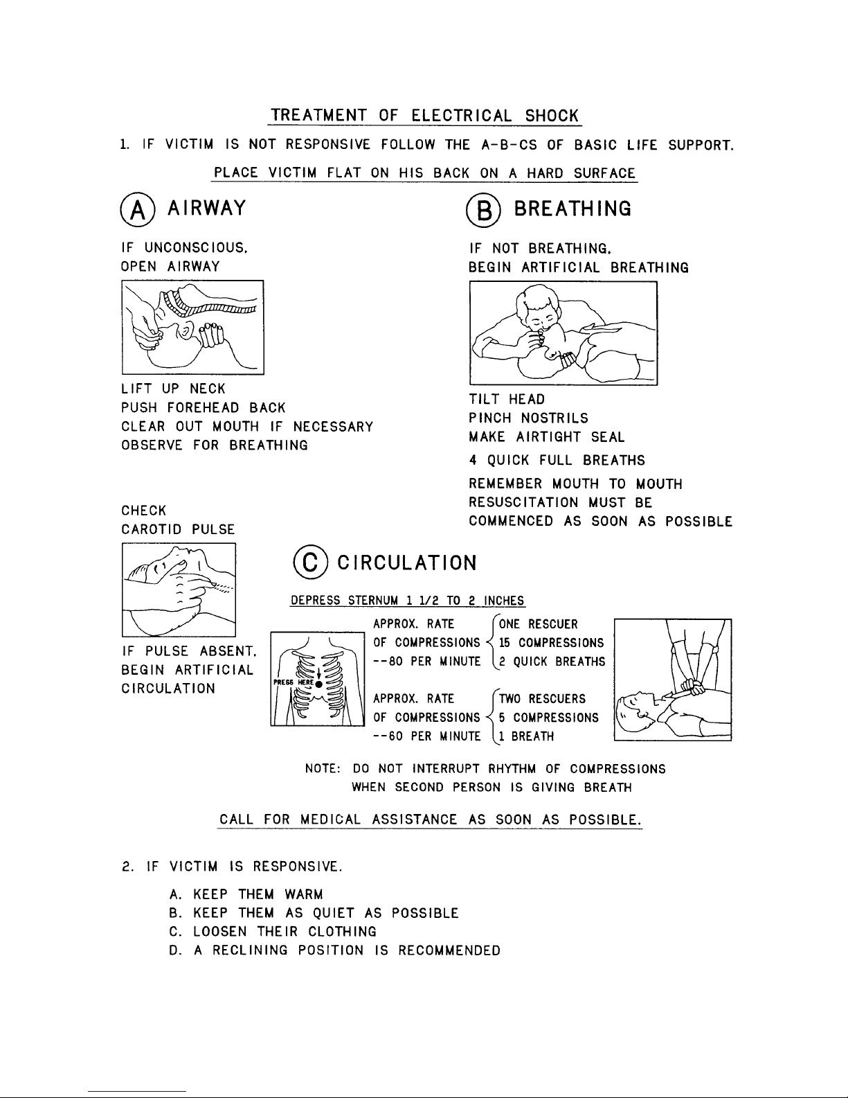
FIRST‐AID
Personnelengagedintheinstallation,operation,maintenanceorservicingofthisequipment
areurgedtobecomefamiliarwithfirst‐aidtheoryandpractices.Thefollowinginformationis
notintendedtobecompletefirst‐aidprocedures,itisabriefandisonlytobeusedasa
reference.Itisthedutyofallpersonnelusingtheequipmenttobepreparedtogiveadequate
EmergencyFirstAidandtherebypreventavoidablelossoflife.
TreatmentofElectricalBurns
1. Extensiveburnedandbrokenskin
a. Coverareawithcleansheetorcloth.(Cleanestavailablecloth
article.)
b. Donotbreakblisters,removetissue,removeadheredparticles
ofclothing,orapplyanysalveorointment.
c. Treatvictimforshockasrequired.
d. Arrangetransportationtoahospitalasquicklyaspossible.
e. Ifarmsorlegsareaffectedkeepthemelevated.
NOTE:
Ifmedicalhelpwillnotbeavailablewithinanhourandthevictimisconsciousand
notvomiting,givehimaweaksolutionofsaltandsoda:1levelteaspoonfulofsalt
and1/2levelteaspoonfulofbakingsodatoeachquartofwater(neitherhotor
cold).Allowvictimtosipslowlyabout4ounces(ahalfofglass)overaperiodof15
minutes.Discontinuefluidifvomitingoccurs.(Donotgivealcohol.)
2. Lesssevereburns‐(1st&2nddegree)
a. Applycool(noticecold)compressesusingthecleanestavailable
clotharticle.
b. Donotbreakblisters,removetissue,removeadheredparticles
ofclothing,orapplysalveorointment.
c. Applycleandrydressingifnecessary.
d. Treatvictimforshockasrequired.
e. Arrangetransportationtoahospitalasquicklyaspossible.
f. Ifarmsorlegsareaffectedkeepthemelevated.
REFERENCE:
ILLINOISHEARTASSOCIATION
AMERICANREDCROSSSTANDARDFIRSTAIDANDPERSONALSAFETYMANUAL
(SECONDEDITION)
WARNING: Disconnect primary power prior to servicing.
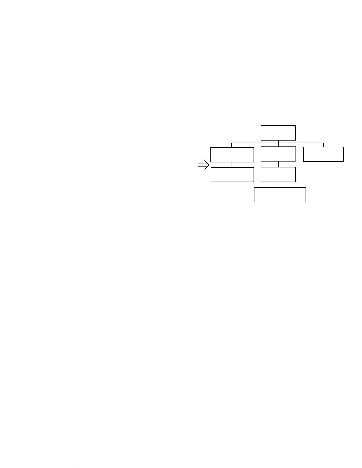
GuidetoUsingPartsListInformation
TheReplaceablePartsListIndexportraysatreestructurewiththemajoritemsbeingleftmostintheindex.The
examplebelowshowstheTransmitterasthehighestiteminthetreestructure.Ifyouweretolookatthebillof
materialstablefortheTransmitteryouwouldfindtheControlCabinet,thePACabinet,andtheOutputCabinet.
IntheReplaceablePartsListIndextheControlCabinet,PACabinet,andOutputCabinetshowupone
indentationlevelbelowtheTransmitterandimpliesthattheyareusedintheTransmitter.TheControllerBoard
isindentedonelevelbelowtheControlCabinetsoitwillshowupinthebillofmaterialfortheControlCabinet.
Thetreestructureofthissameindexisshowntotherightofthetableandshowsindentationlevelversustree
structurelevel.
ExampleofReplaceablePartsListIndexandequivalenttreestructure:
ReplaceablePartsListIndexPartNumberPage
Table7‐1.Transmitter 99592830017‐2
Table7‐2.ControlCabinet 98192440027‐3
Table7‐3.ControllerBoard 90183440027‐6
Table7‐4.PACabinet 98194000027‐7
Table7‐5.PAAmplifier 97178940027‐9
Table7‐6. PAAmplifierBoard90179040027‐10
Table7‐7.OutputCabinet 98194500017‐12
Thepartnumberoftheitemisshowntotherightofthedescriptionasisthepageinthemanualwherethebill
forthatpartnumberstarts.Insidetheactualtables,fourmainheadingsareused:
•Table#‐#.ITEMNAME‐PARTNUMBER‐thislinegivestheinformationthatcorrespondstotheReplace‐
ablePartsListIndexentry;
•PARTNUMBERcolumngivesthetendigitHarrisBroadcastpartnumber(usuallyinascendingorder);
•DESCRIPTIONcolumngivesa25characterorlessdescriptionofthepartnumber;
•REF.SYMBOLS/EXPLANATIONScolumn1)givesthereferencedesignatorsfortheitem(i.e.,C001,R102,
etc.)thatcorrespondstothenumberfoundintheschematics(C001inabillofmaterialisequivalenttoC1
ontheschematic)or2)givesaddedinformationorfurtherexplanation(i.e.,“Usedfor208Voperation
only,”or“UsedforHT10LSonly,”etc.).
NOTE:Insidetheindividualtablessomestandardconventionsareused:
•A#symbolinfrontofacomponentsuchas#C001undertheREF.SYMBOLS/EXPLANATIONScolumnmeans
thatthisitemisusedonorwithC001andisnottheactualpartnumberforC001.
•Inthetendigitpartnumbers,ifthelastthreenumbersare000,theitemisapartthathasbeenpurchased
andhasnotmanufacturedormodified.Ifthelastthreenumbersareotherthan000,theitemiseither
manufacturedorispurchasedfromavendorandmodifiedforuseintheHarrisBroadcastproduct.
•Thefirstthreedigitsofthetendigitpartnumbertellwhichfamilythepartnumberbelongsto‐forexam‐
ple,allelectrolytic(can)capacitorswillbeinthesamefamily(524xxxx000).Ifanelectrolytic(can)capaci‐
torisfoundtohavea9xxxxxxxxxpartnumber(anumberoutsideofthenormalfamilyofnumbers),ithas
probablybeenmodifiedinsomemanneratthefactoryandwillthereforeshowupfartherdownintothe
individualpartslist(becauseeachtableisnormallysortedinascendingorder).MostHarrisBroadcast
madeormodifiedassemblieswillhave9xxxxxxxxxnumbersassociatedwiththem.
Theterm“SEEHIGHERLEVELBILL”inthedescriptioncolumnimpliesthatthereferencedesignatedpartnumber
willshowupinabillthatishigherinthetreestructure.Thisisoftenthecaseforcomponentsthatmaybe
frequencydeterminantorvoltagedeterminantandarecalledoutinahigherlevelbillstructurethatismore
customerdependentthanthebillatalowerlevel.
Transmitter
995 9283 001
Control Cabinet
981 9244 002
Controller Board
901 8344 002
PA Cabinet
981 9400 002
PA Amplifier
971 7894 002
PA Amplifier Board
901 7904 002
Output Cabinet
981 9450 001

TableofContents
1
Copyright©2013,HarrisBroadcast.
Section‐1Introduction
PurposeofThisManual......................1‐1
TechnicalSupport...........................1‐1
FAXOptionsandSparePartsKits...............1‐2
FAX5/10Options...........................1‐2
FAX20Options ............................1‐2
FAX30Options ............................1‐3
FAX40Options ............................1‐3
ExciterOptions............................1‐3
FAXSparePartsKits........................1‐4
FAXTransmitterDescriptionandFeatures .......1‐4
FAX5/10Photos/Mechanical/Cooling/ElectricalData1‐5
FAX20Photos/Mechanical/Cooling/ElectricalData1‐9
FAX30Photos/Mechanical/Cooling/ElectricalData1‐12
FAX40Photos/Mechanical/Cooling/ElectricalData1‐15
FAXSpecifications(AllModels) ................1‐18
SelectingLocationforTransmitterPlacement ...1‐19
Cooling ...................................1‐19
GroundingRequirements ....................1‐21
ACRequirements...........................1‐21
SurgeSuppressionDevices .................1‐21
VoltageRegulation ........................1‐21
RFLineRequirements .......................1‐22
Section‐2Installation
Introduction................................2‐1
Unpacking .................................2‐1
ReturnsandExchanges .......................2‐1
TransmitterDocumentation ...................2‐1
InstallationandOutlineDrawings .............2‐1
PersonnelandEquipmentProtection...........2‐2
SafetyCircuits .............................2‐2
Installation .................................2‐3
RemoveShippingMaterials..................2‐3
SettingTransmitterinPlace..................2‐3
RackMountingFAX5/10 .....................2‐4
EquipmentGround..........................2‐5
Exciter‐TransmitterInterconnection............2‐6
InstallingANon‐HarrisBroadcastExciter .......2‐7
RFConnections.............................2‐9
ACPowerRequirementsandConnection ........2‐9
ACConnectionwithoutDistributionPanel ....2‐10
ACConnectionwithDistributionPanel .......2‐13
CoolingInstallation .........................2‐13
InitialTurnOn .............................2‐13
UserRemoteControlConnection .............2‐15
Section‐3Operation
Introduction ...............................3‐1
ControlsandIndicators ......................3‐1
FrontPanelControlsandIndicators...........3‐1
InternalControlsandIndicators...............3‐3
RFSampleandRTACPorts ..................3‐5
FrontPanelOperation.......................3‐5
ON/OFFOperation.........................3‐6
PowerRaise/LowerProcedure ...............3‐6
RemoteEnable/DisableButtons.............3‐6
LCDNavigationTutorial ......................3‐7
PowerButtonMenu........................3‐9
StatusButtonMenus ........................3‐9
STATUS>LOGMenu .......................3‐12
STATUS>EXCITERMenu ....................3‐13
STATUS>DriveChainMenu.................3‐13
STATUS>POWERAMPMenu................3‐14
STATUS>OUTPUTMenu ...................3‐14
STATUS>POWERSUPPLIESMenu ............3‐16
STATUS>SYSTEMMenu....................3‐16
STATUS>>SWREVISIONS ...................3‐17
STATUS>>TEST ...........................3‐17
SET‐UPButton.............................3‐18
TransmitterSetup/ConfigurationandCalibration 3‐20
SETUP>TXCONTROLMenu.................3‐20
SETUP>SYSTEMSETUPMenu ...............3‐21
SETUP>TXCONFIGURATION ...............3‐21
SETUP>TXCALIBRATE .....................3‐21
SETUP>TXCALIBRATE>TXPOWERCALMenu..3‐21
SETUP>TXCALIBRATE>POWERSUPPLYSET....3‐22
SETUP>TXCALIBRATE>AIRFLOWSET .........3‐22
SETUP>TXCALIBRATE>PWRBLOCKCAL ......3‐23
SETUP>TXCALIBRATE>REJLOADCAL.........3‐24
SETUP>TXCALIBRATE>CALRESTORE.........3‐24
SETUP>EXCITERSETUP ....................3‐24
SETUP>NETWORKSETUP ..................3‐25
SETUP>DISPLAYMODE ....................3‐26
SETUP>RESTOREDEFAULTS.................3‐26
RemoteGraphicalUserInterface(GUI) ........3‐26
GUIHOMESCREEN.......................3‐28
EventLogMenu ..........................3‐29
System>SystemSetupMenu ...............3‐30

TableofContents
2
Copyright©2013,HarrisBroadcast.
System>SystemSetup>SystemServiceMenu..3‐30
System>SystemSetup>SystemConfigMenu ..3‐31
System>SystemSetup>NetworkMenu .......3‐31
System>SystemSetup>Network>SNMPMenu.3‐32
System>SystemSetup>Network>NTPMenu ..3‐32
SYSTEM>SystemSetup>Network>ISPMenu...3‐33
Section‐4Theory
FAXTransmitterConfigurations ...............4‐1
10kWRFBlockDiagramDescription..........4‐1
FAX5RFBlockDiagram .....................4‐3
FAX20RFBlockDiagram ....................4‐4
FAX30RFBlockDiagram ....................4‐5
FAX40RFBlockDiagram ....................4‐6
SystemAPC ..............................4‐6
PAModuleDescription .....................4‐8
PowerSupplySystemDescription............4‐9
FanControlBoardDescription ..............4‐10
FrontPanelControl/DisplayBoardDescription 4‐11
SystemInterfaceControlBoardDescription ...4‐12
Section‐5Maintenance
Introduction...............................5‐1
SafetyPrecautions.........................5‐1
DipswitchSettings..........................5‐1
TransmitterCleaning........................5‐7
AirFilterReplacementProcedure............5‐8
PAModuleCleaningProcedure..............5‐8
PeriodicCleaningandInspection............5‐9
DateandTimeBattery ......................5‐10
PA/PSReplacement........................5‐11
ChangingPA,IPA,&PowerSupplyModules ...5‐11
PowerSupplyModuleReplacementProcedure 5‐12
ConfigurationFile,FaultLogsandSoftwareUpload5‐13
ConfigFileSave/Upload...................5‐13
SaveConfigFile..........................5‐13
UploadConfigFile ........................5‐14
SoftwareUpdateProcedure ................5‐14
Retrieving/PrintingFaultLogs ..............5‐15
SystemCalibrationProcedures ...............5‐16
SystemForward/ReflectedPowerCalibration .5‐16
PowerBlockPowerCalibrationFAX20/30/40Only5‐17
TransmitterAirFlowCalibration ............5‐18
ExciterPowerCalibration/SwitchoverThreshold5‐19
PowerSupplyVoltageSet..................5‐20
RejectLoadCalibration(Power/FanSpeed)FAX20/30/40
Only ...................................5‐20
BackupControlModePowerSetting.........5‐21
UPSModePowerSetup ....................5‐21
IPABypassFAX5/1 0 Only ...................5‐21
BoardandAssemblyReplacementProcedures ..5‐22
BackplaneBoardReplacement..............5‐22
SystemInterfaceControlBoardReplacement ..5‐23
MultiUnitSystemInterfaceBoardReplacement5‐25
ControlandDisplayBoardReplacement ......5‐26
14‐WayPowerSplitterAssemblyReplacement . 5‐27
14‐WayCombinerAssemblyReplacement ....5‐28
Section‐6Diagnostics
Introduction................................6‐1
TroubleshootingTables .......................6‐1
LEDIndicatorExplanation...................6‐1
TransmitterFrontPanelControllerLEDIndicators6‐1
SystemInterfaceControlModuleLEDIndicators 6‐3
TelnetSession ..............................6‐6
Section‐7PartsList
ExplodedView10kWPowerBlock .............7‐1
ACDistributionPanelParts(AllModels) .........7‐4
FAX20/30/40SpecificParts....................7‐4
RejectLoadParts ..........................7‐5
Splitters/Combiners........................7‐5

1‐1
888‐2720‐001 WARNING:Disconnectprimarypowerpriortoservicing. Copyright©2013,HarrisBroadcast
FAX 5/10/20/30/40KW
October 28, 2013
Section-1 Introduction
1
1.1 Purpose of This Manual
Thismanualprovidesimportantinformationfortheproperinstallation,operationandmaintenanceoftheFlexiva
FAXSeriesoftransmittersincludingthe5kW,10kW,20kW,30kW,and40kWsystems.Thevarioussectionsofthe
manualprovidethefollowingtypesofinformation.
•Section1:Identifiestheoptionsavailableincludingsparepartskits.Providesdetailedinformationrequired
priortotheinstallationofthetransmitter,includingmechanical,coolingandelectricaldata,Ground‐
ing,ACMainsrequirementsandRFtransmissionlineinformation.
•Section2:Detailstheproperstepstoinstallthetransmitterandputtingitontheairforthefirsttime.
•Section3:Providesdetailedinformationonhowtoproperlyoperatethetransmitter.
•Section4:DetailstheTheoryofOperationofthetransmitter.
•Section5:Maintenance,detailedstepstoclean,calibrateandchangemodulesinthetransmitter.
•Section6:Troubleshooting,includedasaserviceaidtobeusedalongwithsections4and5byqualifiedperson‐
neltoidentifyandcorrectanequipmentmalfunction.
1.2 Technical Support
HarrisBroadcastoffers24hourtelephonetechnicalsupportforallradioandtelevisionproductsfromtheUnited
States.Togetthebestassistanceasquicklyaspossiblepleasehavethetransmittermodelandserialnumberready
whencallingorsendinganemail.
24‐hourTechnicalSupportandPartsPhone‐1‐217‐222‐8200(followprompts)
24‐hourTechnicalSupportandPartsFAX‐1‐217‐221‐7086(followprompts)
TechnicalSupportEmailAddress‐tsupport@harrisbroadcast.com
Website‐www.harrisbroadcast.com
Customerportalaccesscanbeobtainedviawww.harrisbroadcast.com/servicesandsupport.Customersmust
registerwithausernameandpasswordtogainaccessto;technicaldocumentation,softwareupgradesandservice
bulletins.
OfficesaroundtheGlobe:
NorthAmerica Europe
HarrisBroadcast HarrisBroadcastCommunications
3200WismannLane EskdaleRoad,Winnersh
Quincy,IllinoisUSA62301 Wokingham,Berkshire,U.K.RG415TS
telephone:+12172228200telephone:+44(0)1189648100
facsimile:+12172217086facsimile:+44(0)1189648054
e‐mail:tsupport@harrisbroadcast.come‐mail:supporttx.emea@harrisbroadcast.com

Section-1 Introduction
October 28, 2013
1‐2
Copyright©2013,HarrisBroadcast WARNING:Disconnectprimarypowerpriortoservicing. 888‐2720‐001
Asia
HarrisCommunications(Shenzhen)Ltd.HarrisCommunications(China)
R3‐B2,High‐TechIndustrialPark,Rm3711,CITICSquare
NanshanDist.,ShenzhenChina5180571168NanjingRoad(W)
Telephone: +86(0)7556637928.Shanghai,China200041
facsimile:+86(0)7556637048Telep hon e:+86(0)2152925660
e‐mail:Jmei@harrisbroadcast.com
1.3 FAX Options and Spare Parts Kits
ThissectionsummarizestheoptionsthatareavailableforpurchasewiththeHarrisBroadcastFAXtransmitters.The
FAXcanincorporateanyavailableHarrisBroadcastexciterinbothsingleanddualexciterconfigurations.Thereare
alsoanumberofsparepartskitsavailable,someofwhicharemodeldependant.Pleasesee843‐5614‐102infront
sectionofthedrawingpackageforyourmodeltransmitterforacompletelisting.
1.3.1 FAX5/10 Options
FAX5/10isasinglepowerblockandcanbepurchasedasastandalonetransmitterandrackedinacustomerrack.It
mayalsobepurchasedinaHarrisBroadcastrack.HarrisBroadcastcanprovidethreedifferentmodelracksforthe
FAX5/10transmitter.
DocumentationPackagePartNumber‐943‐5614‐093UnitsmanufacturedpriortoAugust2012
DocumentationPackagePartNumber‐943‐5614‐476UnitsmanufacturedaftertoAugust2012
HarrisBroadcastBasicRack‐981‐0136‐012‐37RURackwithreardoor
HarrisBroadcastBasicRack‐981‐0136‐011‐BasicRack,plusRFLinetotop
HarrisBroadcastDeluxeRack‐981‐0136‐004‐BasicrackplusACPowerDistributionPanel
3‐PhaseDelta ..... 971‐0054‐035
3‐PhaseWye....... 971‐0054‐036
1‐Phase............... 971‐0054‐037
220VACStrip...... 253‐0253‐000
120VACStrip..... 253‐0254‐000
VentedRearDoor‐943‐5602‐481‐Replacessolidpaneldoor
AirPlenumKit‐981‐0031‐027G‐FitsfrontofHarrisBroadcastRackonly
RemoteControlBreakoutBoard‐901‐0218‐201GT‐ConvertsconnectionsfromdB‐25toScrewterminals
1.3.2 FAX20 Options
TheFAX20requiresaHarrisBroadcastrackduethemountingofthepowerblockcombinerandassociatedreject
load.ThebasicrackcomeswiththeRFlineinstalledtotopoftherack.TheACdistributionisanoptioninthedeluxe
rack.
DocumentationPackagePartNumber‐943‐5614‐187UnitsmanufacturedpriortoAugust2012
DocumentationPackagePartNumber‐943‐5614‐321UnitsmanufacturedaftertoAugust2012
3‐PhaseDelta ..... 971‐0054‐038
3‐PhaseWye....... 971‐0054‐039
1‐Phase............... 971‐0054‐040
220VACStrip...... 253‐0253‐000
120VACStrip...... 253‐0254‐000
VentedRearDoor‐943‐5602‐481‐Replacessolidpaneldoor
AirPlenumKit‐981‐0031‐052‐FitsfrontofHarrisBroadcastRackonly
RemoteControlBreakoutBoard‐901‐0218‐201GT‐ConvertsconnectionsfromdB‐25toScrewterminals

FAX 5/10/20/30/40KW
October 28, 2013 1‐3
888‐2720‐001 WARNING:Disconnectprimarypowerpriortoservicing. Copyright©2013,HarrisBroadcast
1.3.3 FAX30 Options
TheFAX30requiresaHarrisBroadcastrackduethemountingofthepowerblockcombinersandassociatedreject
loads.ThebasicrackcomeswiththeRFlineinstalledtotopoftherackandcanbepurchasedwithouttheAC
DistributionPanel.NosinglephaseACDistributionPanelavailableforthismodel.TousesinglephasetotheFAX30,
usethreefeedswithbreakersinawallmountedpanelexternaltothetransmitterrack.
DocumentationPackagePartNumber‐943‐5614‐341UnitsmanufacturedpriortoAugust2012
DocumentationPackagePartNumber‐943‐5614‐478UnitsmanufacturedaftertoAugust2012
3‐PhaseDelta ..... 971‐0054‐041
3‐PhaseWye....... 971‐0054‐042
220VACStrip...... 253‐0253‐000
120VACStrip...... 253‐0254‐000
VentedRearDoor‐943‐5602‐481‐Replacessolidpaneldoor(2required)
AirPlenumKit‐981‐0031‐052‐FitsfrontofHarrisBroadcastRackonly(2required)
RemoteControlBreakoutBoard‐901‐0218‐201GT‐ConvertsconnectionsfromdB‐25toScrewterminals
1.3.4 FAX40 Options
TheFAX40requiresaHarrisBroadcastrackduethemountingofthepowerblockcombinersandassociatedreject
loads.ThebasicrackcomeswiththeRFlineinstalledtotopoftherackandcanbepurchasedwithouttheAC
DistributionPanel.NosinglephaseACDistributionPanelavailableforthismodel.TousesinglephasetotheFAX40,
usefourfeedswithbreakersinawallmountedpanelexternaltothetransmitterrack.
DocumentationPackagePartNumber‐943‐5614‐342UnitsmanufacturedpriortoAugust2012
DocumentationPackagePartNumber‐943‐5614‐478UnitsmanufacturedaftertoAugust2012
3‐PhaseDelta ..... 971‐0054‐043
3‐PhaseWye....... 971‐0054‐044
220VACStrip...... 253‐0253‐000
120VACStrip...... 253‐0254‐000
VentedRearDoor‐943‐5602‐481‐Replacessolidpaneldoor(2required)
AirPlenumKit‐981‐0031‐052‐FitsfrontofHarrisBroadcastRackonly(2required)
RemoteControlBreakoutBoard‐901‐0218‐201GT‐ConvertsconnectionsfromdB‐25toScrewterminals
1.3.5 Exciter Options
ThefollowingExcitersareavailableforinstallationintoanyoftheFAXmodels.Thesecanbeinsingleordualexciter
configurations.ThereisalsoanoptionformountingtheexciterexternaltotheFAXrackeither25or50feetaway.
Pleaseseeexcitermanualforthevariousoptionsavailableforeachmodel.FortheFAXtransmittertooperateinany
HDmodeorinSplitLevelCombinedmode,aHarrisBroadcastFlexStarExciterwithcorrectoptionsisrequired.
FAX50‐995‐0093‐001
FlexstarHDExciter‐995‐0012‐001
DigitDFMExciter‐994‐9410‐005
MicromaxExciter‐HARMICROMAXANALOG
MicromaxExciter‐HARMICROMAXDIGITAL(AESAudiocapable)
Singleexcitercables(foraddingsecondexciter)Standardlength‐952‐9266‐015
DualexcitercablesStandardlength‐952‐9266‐016
Externalmount25footcables(Singleexciters)‐952‐9266‐067
Externalmount50footcables(Singleexciters)‐952‐9266‐068
Externalmount25footcables(Dualexciters)‐952‐9266‐069
Externalmount50footcables(Dualexciters)‐952‐9266‐070

Section-1 Introduction
October 28, 2013
1‐4
Copyright©2013,HarrisBroadcast WARNING:Disconnectprimarypowerpriortoservicing. 888‐2720‐001
1.3.6 FAX Spare Parts Kits
Thefollowingspareskitsareavailable.
FAXSparePartsKit(ALLMODELS):
ModuleSpares‐990‐1201‐001‐Contains1eachPAandPSmodules
FAXSparePartsKitFAX20/30/40:
BoardSpares20K‐990‐1201‐010‐Contains1eachofthecontrolandinterfaceboards
FAXSparePartsKitFAX5/10:
BoardSpares10K‐990‐1201‐002‐Contains1eachofthecontrolandinterfaceboards
BasicSpares10K‐990‐1201‐003‐Containsfusesandafan
FAXSparePartsKitFAX20:
BasicSpares20K‐990‐1201‐004‐Containsfuses,2fans,andrejectloadresistor
FAXSparePartsKitFAX30/40:
BasicSpares30/40K‐990‐1201‐007‐Containsfuses,2fans,andrejectloadresistor
1.4 FAX Transmitter Description and Features
TheFlexivaFAXseriestransmittersarebuiltbasedona10kWbuildingpowerblock.TheFAX10transmitterhasone
powerblock,theFAX5usesthesamepowerblockasaFAX10butfewerPAmodulesandpowersupplies.Forthe
higherpowertransmittersFAX20/30/40,multiple10kWpowerblocksarecombinedusinghybridcombinersto
achievetheirratedpower.Alltransmittersutilizethesamecontrolcardsandsoftware.
FAXTransmitterFeatures
•FMair‐cooledtransmitter
•QuadModeoperationinFM,FM+HD,HDandDRM+
•BroadbanddesignandfrequencyagileacrosstheFMBand88‐108MHz
•HotPluggablePowerSuppliesandPowerAmplifiers
•IncorporatesmultipleHarrisBroadcastexcitermodelsaswellasothermanufacturers‐dualexcitercapability
•ControlviaParallelI/O,EthernetandSNMP
•RoHS7CECompliant
•TypicalefficiencyACtoRFof70%
•HasbackuphardwarecontrolifMicroModulewouldfail
•SFN,Main/AltandN+1Systemsavailable

FAX 5/10/20/30/40KW
October 28, 2013 1‐5
888‐2720‐001 WARNING:Disconnectprimarypowerpriortoservicing. Copyright©2013,HarrisBroadcast
1.5 FAX5/10 Photos/Mechanical/Cooling/Electrical Data
Figure 1-1 FAX5/10 Transmitter System Front View
TheFAX10transmittersystemshownissetupwithdualexciterstoprovideredundancyforadditionalon‐air
reliability.ExciterAinthelowerpositionintherackisalwaysthemainexciterinthesystem.TheupperExciterBis
alwaysthebackupexciterinthesystem.ThesepositionsholdtrueforallmodelofhighpowerFAXTransmitters.
TheFAX5isthesamechassisandhardwarebutcontainsfourlesspoweramplifiersandthreelesspowersupply
modules.SeeSection4fordetaileddifferencesbetweenFAX5andFAX10.
Note
For Outline drawing and Rack mechanical information see drawing 843-5614-103 in the documentation
package. The Electrical and HVAC contractors should be provided a copy of this drawing for reference.
Exciter B Flexiva
FAX 10kW
Transmitter
Exciter A
10kW
10kW
Transmitter

Section-1 Introduction
October 28, 2013
1‐6
Copyright©2013,HarrisBroadcast WARNING:Disconnectprimarypowerpriortoservicing. 888‐2720‐001
Figure 1-2 FAX5/10 in Harris Broadcast Deluxe Rack Rear View
This manual suits for next models
4
Table of contents
Popular Transmitter manuals by other brands


Moore Industries
Moore Industries Temperature Concentrator System user manual

Automated Logic
Automated Logic LS3-WT Installation and operating instructions

ENMET
ENMET EX-5150 MOS Operation and maintenance manual

Sennheiser
Sennheiser CHG 2W instruction manual

Long Range Systems
Long Range Systems T7400 user manual

Emerson
Emerson Rosemount 3051 quick start guide