ENMET EX-5150 MOS User manual


EX-5150
ENMET
Manual Revision Date – June 14, 2017
Page | 1
Manual Part No. – 80003-097
Table of Contents
1.0 INTRODUCTION....................................................................................................................................................................2
1.1 Unpack.............................................................................................................................................................................................2
1.2 Check Order.....................................................................................................................................................................................2
1.3 Serial Numbers.................................................................................................................................................................................2
2.0 FEATURES OF THE EX-5150-MOS........................................................................................................................................3
3.0 INSTALLATION OF THE EX-5150-MOS .................................................................................................................................4
3.1 Mounting the EX-5150-MOS Enclosure .........................................................................................................................................4
3.2 Wiring the EX-5150-MOS to a Control Unit...................................................................................................................................5
4.0 OPERATION OF THE EX-5150-MOS......................................................................................................................................7
4.1 Start up.............................................................................................................................................................................................7
4.1.1 Typical Start Up..............................................................................................................................................................................................7
4.1.2 Alternate Start Up...........................................................................................................................................................................................7
4.1.3 Purge ..............................................................................................................................................................................................................8
4.2 Normal Display Mode......................................................................................................................................................................8
4.2.1 Alarm Conditions EX-5150-MOS ...................................................................................................................................................................8
5.0 MAINTENANCE OF THE EX-5150-MOS.................................................................................................................................9
5.1 Maintenance Menu...........................................................................................................................................................................9
5.2 Calibration of the EX-5150-MOS..................................................................................................................................................10
5.2.1 Zero Adjust.................................................................................................................................................................................................... 12
5.2.2 Gas Span.....................................................................................................................................................................................12
5.2.3 Exit Maintenance Menu................................................................................................................................................................................ 12
5.3 Heater Voltage Settings .................................................................................................................................................................14
5.4 Sensor Replacement.......................................................................................................................................................................14
6.0 REPLACEMENT PART NUMBERS .........................................................................................................................................14
7.0 TERMS AND CONDITIONS ...................................................................................................................................................16
7.1 Ordering Information.....................................................................................................................................................................16
7.2 Delivery .........................................................................................................................................................................................16
7.3 Payment Terms ..............................................................................................................................................................................16
7.4 Warranty Information and Guidelines ...........................................................................................................................................16
7.5 Return Policy .................................................................................................................................................................................16
8.0 INSTRUCTIONS FOR RETURNING AN INSTRUMENT FOR SERVICE...........................................................................................17
List of Figures
Figure 1: EX-5150-MOS Features.............................................................................................................................................................3
Figure 2: EX-5150-MOS Mounting Dimensions.......................................................................................................................................4
Figure 3: Terminal Positions EX-5150-MOS Sensor/Transmitter.............................................................................................................6
Figure 4: Calibration Adapter EX-5150-MOS Sensor/Transmitter .........................................................................................................10
Figure 5: EX-5150-MOS Maintenance Menu Flow Chart.......................................................................................................................13
List of Tables
Table 1: EX-5150-MOS Maintenance Menus Sequence...........................................................................................................................9
Table 2: Standard and Non-Standard Calibration Gas.............................................................................................................................11
Reference Information:
NOTE:[important information about use of instrument]
CAUTION:[affects equipment – if not followed may cause damage to instrument, sensor etc.…]
WARNING:[affects personnel safety – if not followed may cause bodily injury or death.]
Attention / Warning
Earth Ground
!

EX-5150
ENMET
Manual Revision Date – June 14, 2017
Page | 2
Manual Part No. – 80003-097
1.0 Introduction
The ENMET EX-5150-MOS sensor/transmitters (S/T) is a 3-wire 24 VDC 4-20mA S/T for the detection of combustible and toxic gas,
utilizing a Metal Oxide Semiconductor (MOS) sensor. The EX-5150-MOS is meant to be used in conjunction with an appropriate
power supply and controller. Each EX-5150-MOS sensor transmitter is in an enclosure rated for use in a Class I, Div. 1, Groups B, C,
D, classified area.
NOTE:All specifications stated in this manual may change without notice.
1.1 Unpack
Unpack the EX-5150-MOS and examine it for shipping damage. If such damage is observed, notify both ENMET customer
service personnel and the commercial carrier involved immediately.
Regarding Damaged Shipments
NOTE: It is your responsibility to follow these instructions. If they are not followed, the carrier will not honor any claims for
damage.
•This shipment was carefully inspected, verified and properly packaged at ENMET and delivered to the carrier in good
condition.
•When it was picked up by the carrier at ENMET, it legally became your company’s property.
•If your shipment arrives damaged:
oKeep the items, packing material, and carton “As Is.” Within 5 days of receipt, notify the carrier’s local office and request
immediate inspection of the carton and the contents.
oAfter the inspection and after you have received written acknowledgment of the damage from the carrier, contact ENMET
Customer Service for return authorization and further instructions. Please have your Purchase Order and Sales Order
numbers available.
•ENMET either repairs or replaces damaged equipment and invoices the carrier to the extent of the liability coverage, usually
$100.00. Repair or replacement charges above that value are your company’s responsibility.
•The shipping company may offer optional insurance coverage. ENMET only insures shipments with the shipping company
when asked to do so in writing by our customer. If you need your shipments insured, please forward a written request to
ENMET Customer Service.
Regarding Shortages
If there are any shortages or questions regarding this shipment, please notify ENMET Customer Service within 5 days of receipt at
the following address: ENMET
680 Fairfield Court
Ann Arbor, MI 48108
734-761-1270 Fax 734-761-3220
Toll Free: 800-521-2978
1.2 Check Order
Check, the contents of the shipment against the purchase order. Verify that the EX-5150-MOS is received as ordered. [Each EX-
5150-MOS is labeled with its target gas.] If there are accessories on the order, ascertain that they are present. Check the contents of
calibration kits. Notify ENMET customer service personnel of any discrepancy immediately.
1.3 Serial Numbers
Each EX-5150-MOS is serialized. These numbers are on tags on the equipment and are on record in an ENMET database.

EX-5150
ENMET
Manual Revision Date – June 14, 2017
Page | 3
Manual Part No. – 80003-097
2.0 Features of the EX-5150-MOS
See Figure 1 for location of features:
Feature
Description
Display
LCD: Indicates the level of gas detected by sensor
Gain Potentiometer
(POT)
POT 1: Display contrast adjustment
POT 2: Does Not apply to MOS, not used Do not adjust
POT 3: Does Not apply to MOS, not used Do not adjust
POT 4: MOS Heater Voltage, do not adjust unless advised by ENMET
Visual Alarms
LED indicators:
Power / Fault Indicator LED, Green / Red
Alarm (3) Indicator LED, Red
Magnetic Switches
M
ENU
: Advances the instrument display through menus (Zero, Span, Exit)
SELECT: Selects the Zero, Span, exit menu or sets proper calibration values for Zero or Span
Sensor
For sensing gas at PPM or LEL levels, see Table 3 for sensor types
Magnetic switches control the instrument maintenance functions. The switch locations are indicated by MENU and SELECT. A
magnetic field pulse is applied by momentarily putting the end of the magnet in proximity to the switch and then removing it.
Referred to as tap. Since the magnetic field penetrates the window, the enclosure cover is not removed to perform calibration.
Three alarm points are preprogrammed into the EX-5150-MOS sensor/transmitters. At each alarm point, an LED on the front panel is
activated. These internal alarm settings are independent of the 4-20mA output alarm values that can be set at a controller. An
optional relay board is available that will activate 0.5 Amp relay contacts at each alarm point, plus a fault relay.
Figure 1: EX-5150-MOS Features
POT 3
See Note
3 Alarm
Indicators
Power /Fault
Indicator
Display
M
ENU
Magnetic switch
S
ELECT
Magnetic switch
Sensor
Sensor ID is stamped on
the sensor collar:
For example, 1
12
13
32
Menu
Select
External View
XX
POT 4
POT 2
See Note
POT 1
Internal PCB View
NOTE: POT 2 and POT 3 are not used
with EX-5150-MOS
Do Not Adjust
EX-5150
ENMET
Manual Revision Date – June 14, 2017
Page | 4
Manual Part No. – 80003-097
3.0 Installation of the EX-5150-MOS
CAUTION:Area must be declassified during installation.
The ENMET EX-5150-MOS gas sensor/transmitter (S/T) is a 3-wire, 24 VDC, 4-20 mA S/T for the detection of toxic or combustible
gas. The S/T is meant to be used in conjunction with an appropriate power supply and controller. The ENMET EX-5150-MOS
sensor transmitter is in an enclosure rated for use in a Class I, Div. 1, Groups B, C, D, classified area. Appropriate wiring, conduit and
fittings are required for proper installation in a explosion proof rated environment.
CAUTION:Since the sensor/transmitter detects gas only at the sensor location, pay attention to the possible sources of gas, the density
of the gas, locations where the gas may be confined and locations where the gas may damage or injure property or personnel, when
choosing locations of sensor/transmitters.
Also, take into consideration environmental factors when deciding on S/T location. Avoid locations where the S/T may be damaged
by liquid immersion, excessive heat or other know hazards. Also, take precautions to insure condensation inside of the conduit does
not enter the S/T.
3.1 Mounting the EX-5150-MOS Enclosure
Mount the enclosure, using the two mounting holes provided see Figure 2. Pay particular attention to the source and density of the
gas being detected when choosing the location. Mount the S/T near the ceiling for lighter than air gases /vapors and near the floor
for heavier then air gas/vapors. Contact ENMET if you have questions regarding your application.
CAUTION:Before connecting S/T to controller remove the power source to controller. Failure to do so may cause damage to
sensitive components.
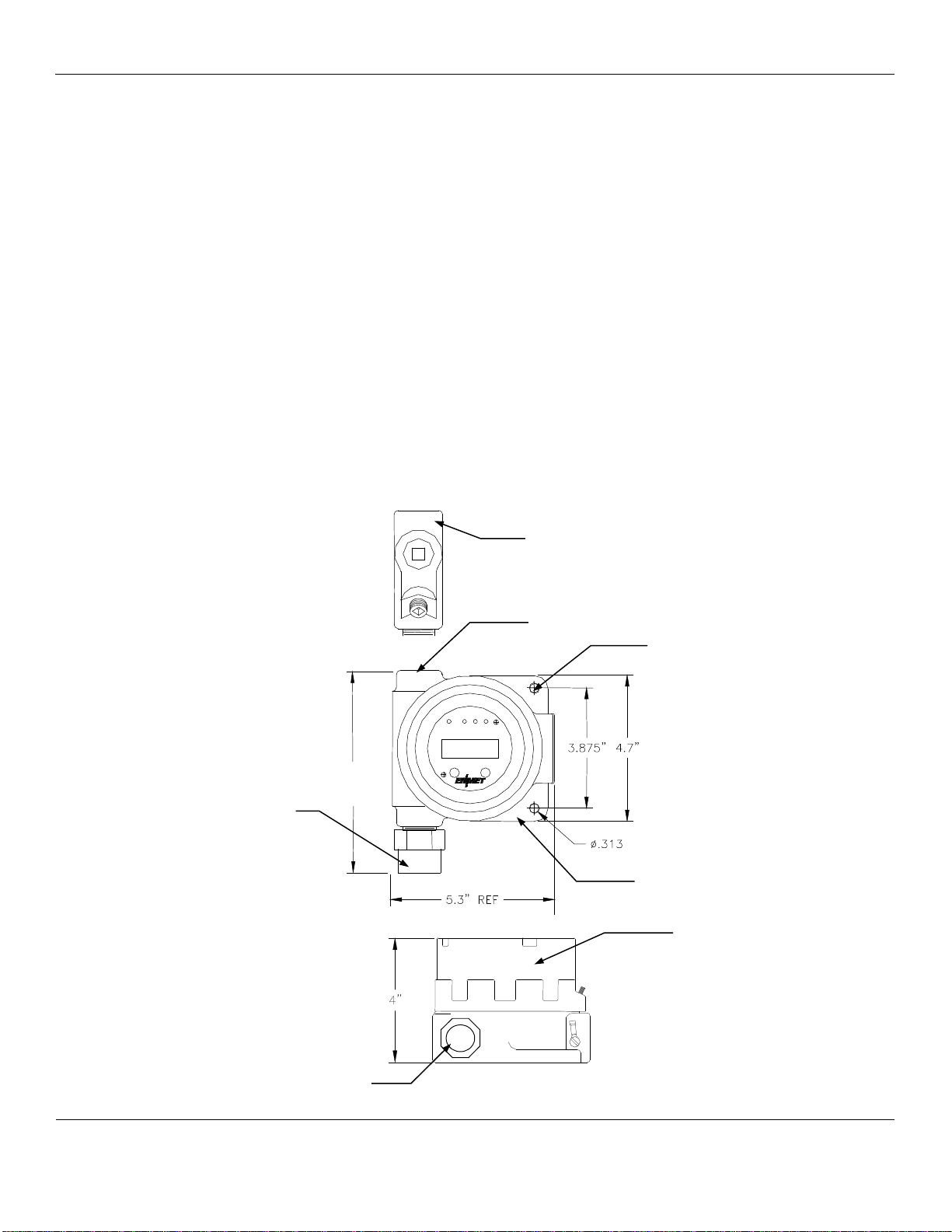
Figure 2: EX-5150-MOS Mounting Dimensions
Optional
Conduit fitting
Typically: ½″NPT female
Mounting Holes
2 places, 0.313
″
TOP VIEW
Sensor
Sensor/Transmitter
Enclosure Top View
Sensor/Transmitter
Enclosure Side View
Sensor
SIDE VIEW
Select
Menu
½″NPT female
7”
EX-5150
ENMET
Manual Revision Date – June 14, 2017
Page | 5
Manual Part No. – 80003-097
3.2 Wiring the EX-5150-MOS to a Control Unit
CAUTION:Area must be declassified during installation.
Run conduit and 16 AWG (1.5MM2) wires to the enclosure from the power supply and controller. If the EX-5150-MOS is installed
in a hazardous location as defined by the National Electrical Code, then ALL wiring must be in accordance with the National code
and any local governing codes.
Open the enclosure, and remove the 2 screws that retain the display overlay to the circuit board.
Use caution when removing the over lay. Do not damage the magnetic switches.
Remove the two overlay standoffs and remove the circuit board, exposing the terminal strips on the bottom of the circuit board.
Do not disconnect the circuit board wiring.
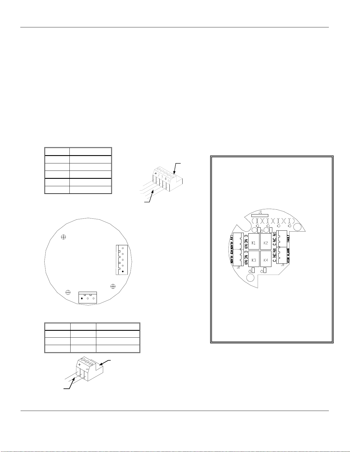
Connect the wires from the controller (power supply) to the supplied J4 plug then attach to J4 terminal.
Connect the wires from the sensor to the supplied J8 plug then attach to the J8 terminal.
See Figure 3 for locations
J4 PLUG –TERMINAL TO CONTROLLER WIRING
Position
Function
1 +
24 V
DC
power
2
GND
3
4 - 20 mA out
4*
RS-485 D+
5*
RS-485 D–
*Contact ENMET for Modbus
Address information
J8 PLUG –TERMINAL TO SENSOR WIRING
Position
Function
MOS Sensor
1 +
Heater
Orange
2
Signal
Blue
3 –
GND
Brown
Relay Output Board Bottom View
Optional Relay Output Board
It is recommended that the auxiliary
alarm be powered separately.
Use 14 – 20 AWG (2.5 –0.5 MM2) wire.
When on power the relays are energized.
Relays are rated at 0.5 Amp continuous.
N
OTE
:Auxiliary alarms should be powered
from an independent power source separate
from the instrument power to avoid alarm
failure due to controller malfunction.
ALL wiring must be in accordance with the
National code and any local governing codes.
Circuit Board Bottom View
5
4
3
J4
J8
1 2 3
Plug J4
To J4
Wires to
Controller
Plug J8
To J8
Wires to
Sensor
2
EX-5150
ENMET
Manual Revision Date – June 14, 2017
Page | 6
Manual Part No. – 80003-097
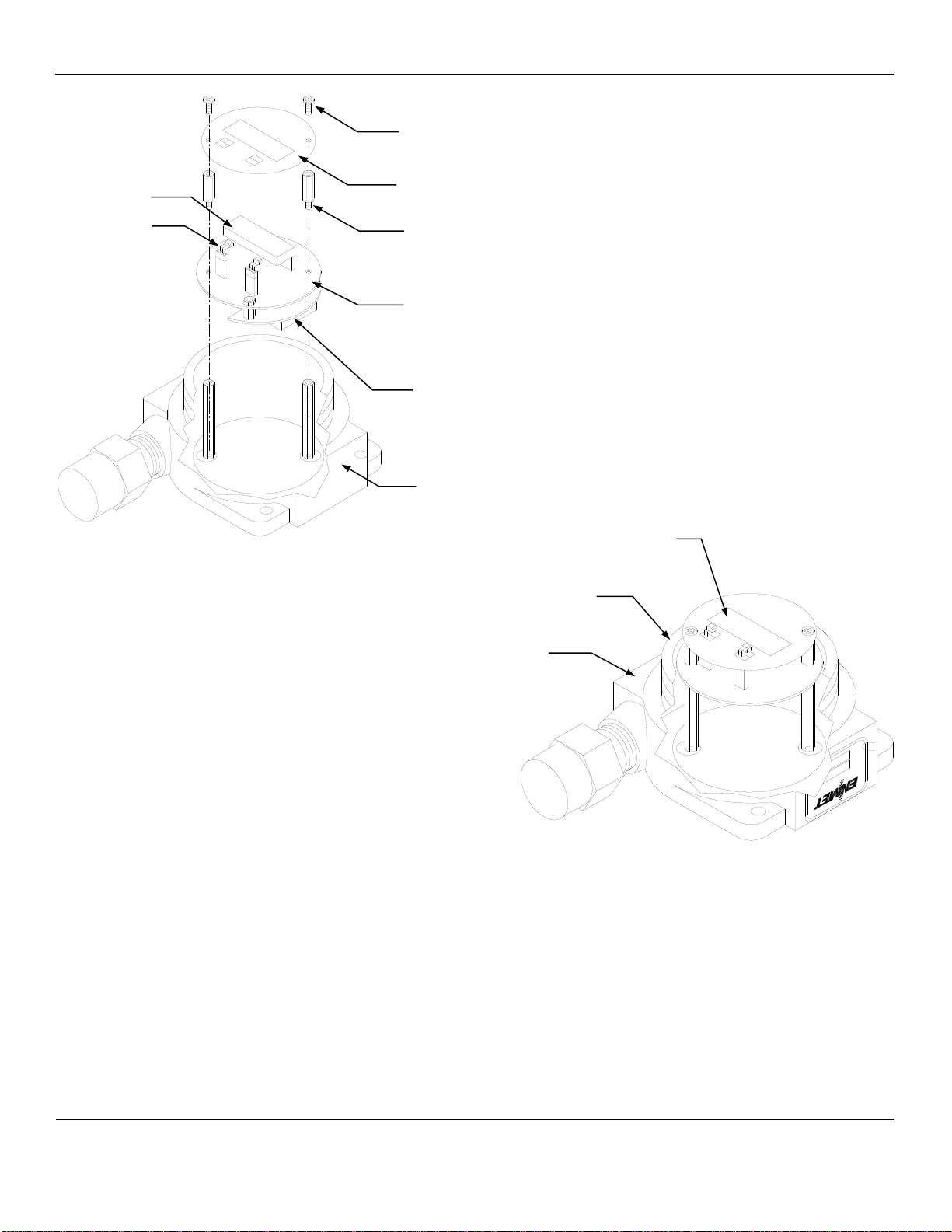
Figure 3: Terminal Positions EX-5150-MOS Sensor/Transmitter
When wiring is complete re-assemble the EX-5150-MOS. Use caution when installing the overlay so as not to damage the
magnetic switches. Put the cover back on the S/T Do Not apply power to the S/T without the cover in place.
Sensor/Transmitter
Enclosure Cutaway View
Printed Circuit Board
(PCB)
Display Overlay
Display Overlay Screws
(2 places)
Display Overlay Standoffs
(2 places)
Magnetic
Switches
(2 places)
Magnetic Switches
(2 places)
Printed Circuit Board (PCB)
J4 and J8 Terminals are located on the
bottom side of PCB
Display Overlay
Display
Optional
Relay Output Circuit Board
EX-5150
ENMET
Manual Revision Date – June 14, 2017
Page | 7
Manual Part No. – 80003-097
4.0 Operation of the EX-5150-MOS
It is best to have the EX-5150-MOS transmitters powered up and operational for 24 hours before applying calibration or test gas to
them.
When the EX-5150-MOS transmitter is first powered up, it goes through a series of momentary screens, which identify the instrument
model number, serial number and software revision. After all the momentary screens have been displayed, the instrument arrives at
the Main Gas Display showing the gas concentration and unit of measurement.
Depending on transmitter configuration and calibration condition, the furthest right character in the display may flash a letter
indicating the instrument status. See the Section 4.1.2 below.
4.1 Start up
4.1.1 Typical Start Up
When power is supplied to the EX-5150-MOS, the S/T will display the following sequence of information:
NOTE:Software revision may cause variations of display output.
Example of Display
Function
The instrument: Model EX-5150-MOS
Note MOS is not displayed
The instrument: Serial Number
The instrument: Software Revision
IF the right most character is a flashing W
OR
The instrument is in Warm-up mode
This should last about 1 minute
The Signal Output is held at 4mA during warm-up
For Toxic Gas OR
The instrument: Normal Display Mode
Measurement of target Gas
IF the right most character is a flashing C, F, P or R See Section 4.1.2
4.1.2 Alternate Start Up
Depending on EX-5150-MOS S/T configuration and calibration condition, the furthest right character in the display may flash
a letter indicating the instrument status. See the table below.
Purging occurs automatically for instruments with sensors that require purging. Purge will occur for 5 minutes on instrument
start-up, followed by a 5-minute recovery period. At the end of the recovery period, the transmitter should be ready for
operation. If additional purge time is required, refer to Section 4.1.3 for more information.
Example of Display (may also display 0 LEC)
Function
IF the right most
character is a flashing C
The last calibration of the instrument was invalid
The instrument must be recalibrated
IF the right most
character is a flashing F
There is a sensor fault
IF the right most
character is a flashing P
The sensor is being purged:
This function is required for certain sensor types
The duration of purge cycle varies with sensor type
The Signal Output is held at 4mA during purge
IF the right most
character is a flashing R
The instrument is in Recovery mode after completing the
purge cycle
This should take about 5 minutes
EX-5150
73-1256
S/W X.X
0ppm
0ppmW
0ppmC
0ppmF
0ppmP
0ppmR
0 LEW
0 LEL
EX-5150
ENMET
Manual Revision Date – June 14, 2017
Page | 8
Manual Part No. – 80003-097
4.1.3 Purge
Purging is a function that temporarily increases the sensor heater voltage to clean off contaminants. Some sensors operate at
higher heater voltages where purging is not required. The EX-5150-MOS S/T is configured at the factory for the installed
sensor purging requirements.
Purge times vary form 5 – 25 minutes depending on the sensor installed.
Some sensors require additional purge time after start up. Particularly if the sensor is new or the system powered down for an
extended period.
To initiate a purge: Turn the power off and back on. This will initialize a purge cycle.
See Figure 5 for the Operational portion of the Maintenance Menu Flow Chart.
4.2 Normal Display Mode
When the EX-5150-MOS is installed as described in section 3, and in clean air, the POWER green LED is on, the display is lit and
the information on the display is measurement of the target gas detected by the EX-5150-MOS.The red alarm and fault LEDs are
not lit.
To advance through displays of operational information tap the magnet over the MENU button.
NOTE:Software revision may cause variations of display output.
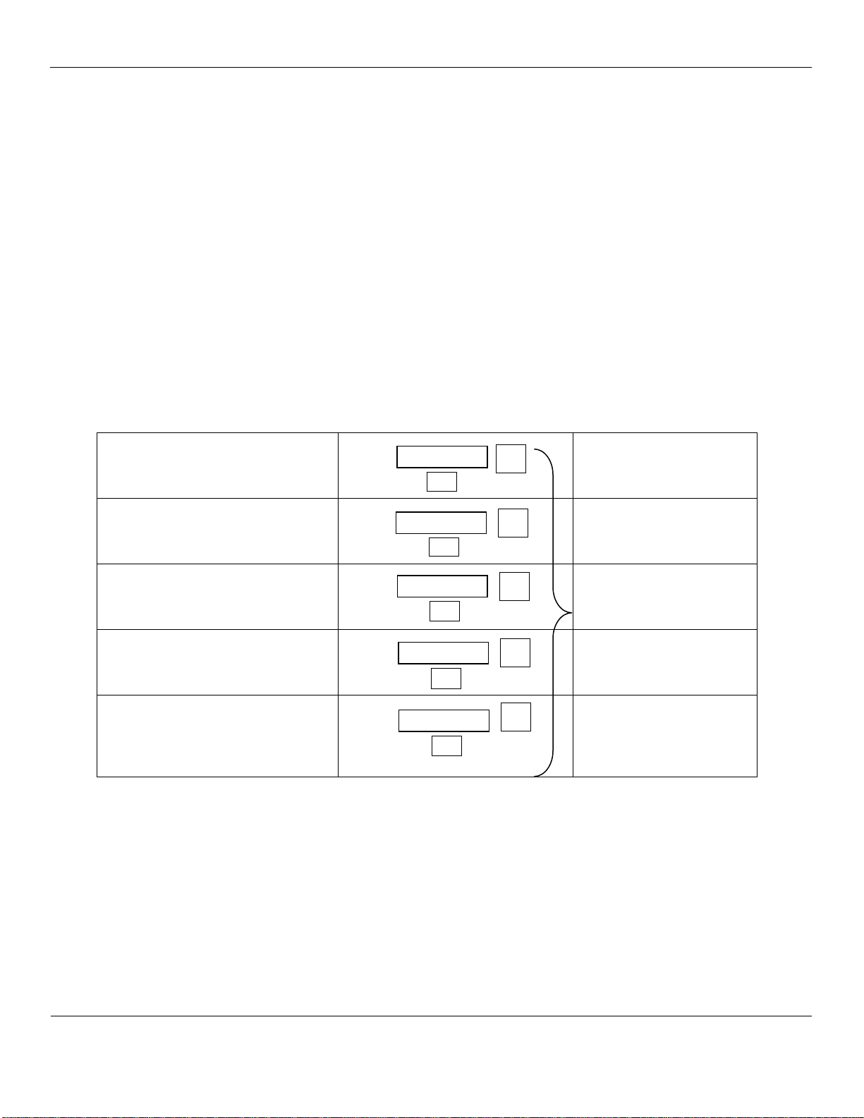
See sequence of operational information below:
Display Measurement of the target gas
Tap the magnet over the MENU button
Display indicates Alarm 1 Set point
Tap the magnet over the MENU button
Display indicates Alarm 2 Set point
Tap the magnet over the MENU button
No Function for the
SELECT button
in this mode
Display indicates Alarm 3 Set point
Tap the magnet over the MENU button
Display indicates mA Span range
(Full Scale)
Tap the magnet over the MENU button
Display returns to gas measurement
Operational Display Flow Chart
4.2.1 Alarm Conditions EX-5150-MOS
There are three alarm set points available. The alarm set points can be changed within limits; see the maintenance section of
this manual for the procedure.
If the gas concentration increases above that of the alarm set point, the associated red LED is lit.
0LEL
A1: 10
S
ELECT
S
ELECT
M
ENU
M
ENU
A2: 20
SELECT
M
ENU
A3: 50
S
ELECT
M
ENU
mA: 100
S
ELECT
M
ENU
EX-5150
ENMET
Manual Revision Date – June 14, 2017
Page | 9
Manual Part No. – 80003-097
5.0 Maintenance of the EX-5150-MOS
CAUTION:Do not open the EX-5150-MOS S/T in a classified area.
CAUTION:Do Not Attempt a Span Procedure Without Calibration Gas Applied to The Sensor; if this is done, the S/T is forced into a
calibration fault mode.
Magnetic switches control the MENU and SELECT functions. The MENU and SELECT switch locations are indicated on the display
panel, see Figure 3. The MENU switch is used to display the various menu options and make incremental changes to numbers such as
alarm points, calibrations gas, etc. The SELECT switch is used to select that option, set zero or span digit. Most maintenance
functions are controlled by simple taps of the supplied magnet on the transmitter glass, below the MENU and SELECT boxes on the
front panel.
5.1 Maintenance Menu
To enter the maintenance menu, hold the magnet over the MENU switch for 2 to 4 seconds
Table 1 indicates the maintenance menu sequence see Figure 5 for a detailed maintenance menu flow chart.
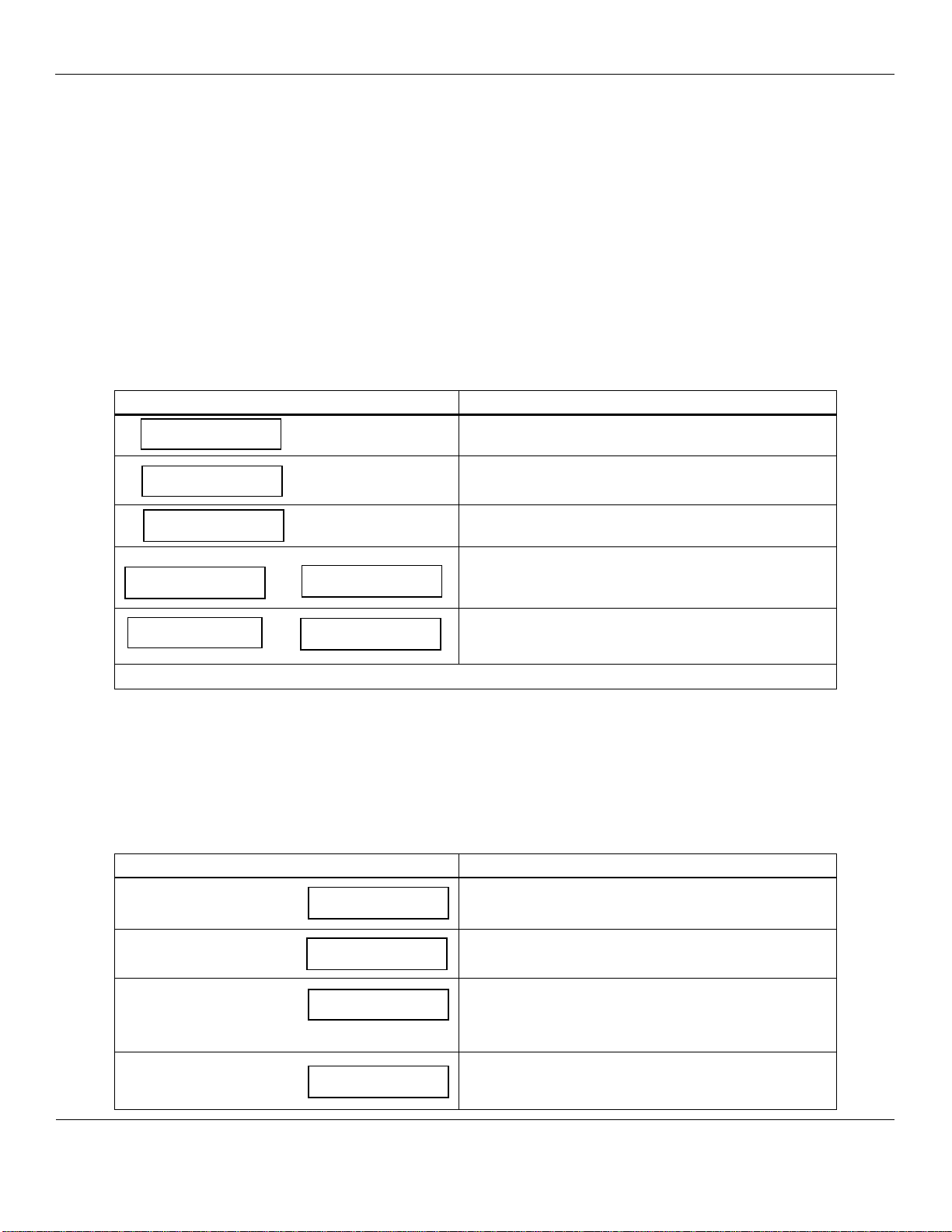
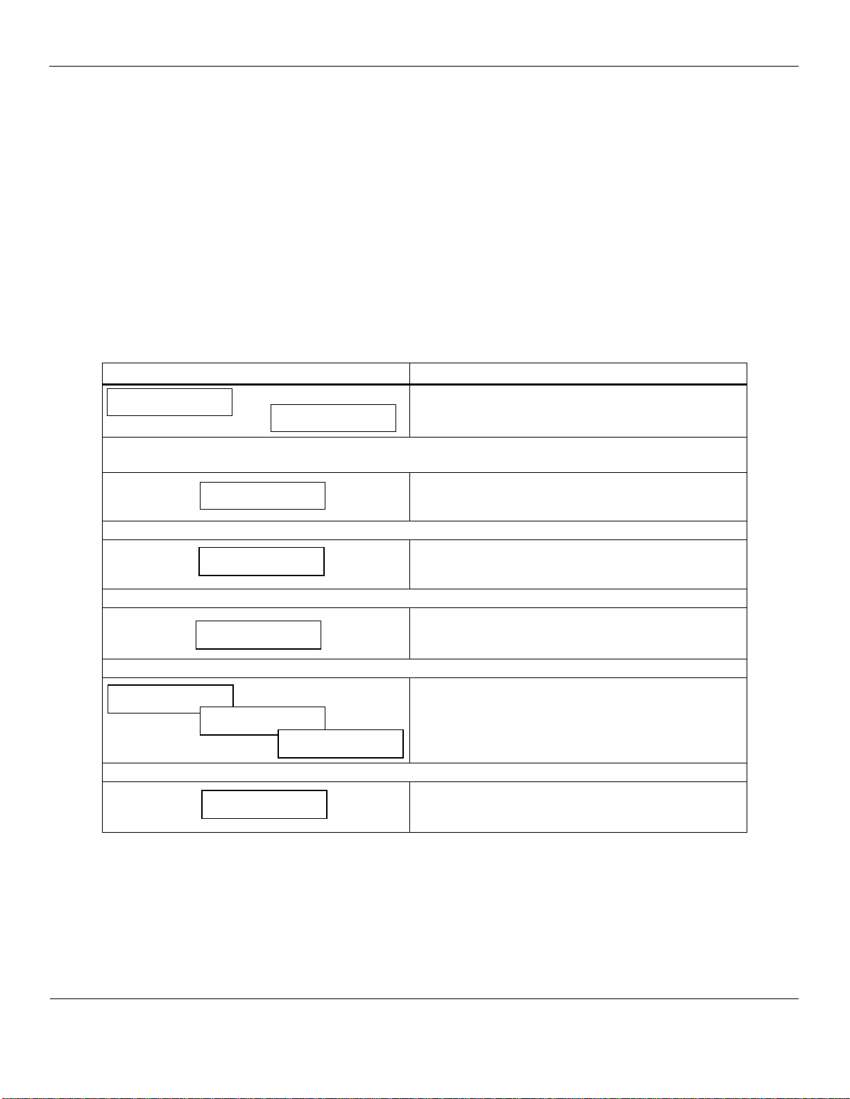
Table 1: EX-5150-MOS Maintenance Menus Sequence
Example of Display
Function
OR
Normal Display Mode
Measurement of target gas
Hold the magnet over M
ENU
switch for 2 – 5 seconds to enter the Maintenance Menu
The Power/Fault LED will flash Green – Red to indicate the EX-5150-MOS is in Maintenance Mode
To exit the maintenance Menu and return to the Normal
Display Mode:
If intended function Tap the magnet over SELECT switch
Tap the magnet over the M
ENU
switch to advance to the Zero procedure
For adjusting Zero:
If intended function Tap the magnet over SELECT switch
Tap the magnet over the M
ENU
switch to advance to the Span procedure
For adjusting the Span:
If intended function Tap the magnet over SELECT switch
Tap the magnet over the M
ENU
switch to advance to each Alarm set point procedures
For adjusting the Alarm 1, 2 and 3 set points:
If Intended Function, Tap the magnet over SELECT
switch
Tap the magnet over the M
ENU
switch to advance the mA Span set point procedure
For adjusting the mA Span set point:
If intended function Tap the magnet over SELECT switch
Taping the MENU switch without taping the SELECT switch will allow you to cycle through the menu options.
You must Tap the SELECT switch to change the desired operation.
NOTE:If the S/T fails to respond, the magnet may have become weak and may need to be replaced.
5ppm
Exit
Zero
Span
mA Span
Alarm1
Alarm2 Alarm3
5LEL

EX-5150
ENMET
Manual Revision Date – June 14, 2017
Page | 10
Manual Part No. – 80003-097
5.2 Calibration of the EX-5150-MOS
Calibration is the process of setting the instrument up to read accurately when exposed to a target gas. The Zero function sets the
clean air reference point and the Span function sets the sensitivity of the instrument.
Initial Calibration: Wait 24 hours after initially supplying power to the EX-5150-MOS sensor/transmitter (S/T) before initial
calibration. The S/T has been precalibrated at the factory, and initial field calibration should result in only fine tuning to circuit, as
well to check that installation is successful. It is not necessary to open the enclosure to make adjustment. The calibration
functions are operated with magnets from outside the enclosure through the MENU and SELECT switches. Do Not open the S/T
unless the area is de-classified.
Calibration Zero and Span functions are two separate procedures. They operate independently of each other. It is recommended
that the Zero procedure be done prior to the Span procedure. ENMET Corporation recommends at least quarterly calibration of
the EX-5150-MOS transmitters.
Calibration equipment is available from ENMET Corporation to calibrate the EX-5150-MOS sensor/transmitters. A calibration
adapter will have a fitting for the gas cylinder on one side, and a cover to go over the sensor housing on the other.
Generally, a cylinder of 20.9% Oxygen is used to provide a fresh air reference or Zero point for the calibration. Another cylinder
is used to provide the Span reference point for calibration. Depending on the instrument calibration, the Span gas may be the same
gas that the instrument is calibrated to display, or it may be another gas, which ENMET has found to have a similar response.
Sensors require a humidified calibration gas sample. Fill the humidifier bowl, half way up with clean fresh water prior to
attaching the Zero or Span gases. Be careful not to let the humidifier bowl tip, allowing water to enter the gas delivery tubing.
See Table 2 for standard and Non-standard calibration gases.
NOTE:Gas flow is opposite to arrow on humidifier
Figure 4: Calibration Adapter EX-5150-MOS Sensor/Transmitter
Calibration Cover
See insert below for
proper gas flow
Humidifier
Select
Menu
Select
Menu
Regulator
Gas Cylinder
Humidifier Top View
TO CAL COVER
&
S
ENSOR
F
ROM
REGULATOR &
G
AS CYLINDER

EX-5150
ENMET
Manual Revision Date – June 14, 2017
Page | 11
Manual Part No. – 80003-097
Table 2: Standard and Non-Standard Calibration Gas
Gas
Range
Alarm 1*
Alarm 2*
Alarm
3*
Sensor
Part Number
Span
Calibration Gas
Calibration Point
Gas Type/ Standard
Methane
0 – 50
%LEL
10% LEL
20%
LEL
40%
LEL
03033-813
20% LEL Methane
20% LEL Methane
Propane
0 – 50
%LEL
10% LEL
20%
LEL
40%
LEL
03033-813
20% LEL Propane
20% LEL Propane
Butane
0 – 50
%LEL
10% LEL
20%
LEL
40%
LEL
03033-813
20% LEL Butane
20% LEL Butane
Methyl Chloride
0 – 400
PPM
100 PPM
200 PPM
300
PPM
03033-812
100 PPM
Methyl Chloride
100 PPM
Methyl Chloride
Carbon Monoxide
0 – 400
PPM
35 PPM
50 PPM
100
PPM
03033-109
100 PPM
Carbon Monoxide
100 PPM
Carbon Monoxide
Hydrogen Sulfide
0 – 100
PPM
10 PPM
20 PPM
50 PPM
03033-812
100 PPM
Carbon Monoxide
20 PPM
Hydrogen Sulfide
Hydrogen
0 – 1000
PPM
200 PPM
500 PPM
800
PPM
03033-813
800 PPM
Hydrogen
800 PPM Hydrogen
Gas Type/ Non – Standard
Considered Special Calibrations, use for examples only. Consult ENMET for specifications and availability.
Ammonia
0 – 300
PPM
150 PPM
300 PPM
300
PPM
03033-019
300 PPM
Ammonia
See Addendum
Ammonia Calibration
Freon 134A
0 – 2000
PPM
500 PPM
1000
PPM
1500
PPM
03032-832
2% LEL Methane
1200 PPM Freon 134
Freon 12
0 – 2000
PPM
500 PPM
1000
PPM
1500
PPM
03032-832
300 PPM
Carbon Monoxide
1200 PPM Freon 12
Freon 22
0 – 2000
PPM
500 PPM
1000
PPM
1500
PPM
03032-832
2% LEL Methane
730 PPM Freon 22
Acetone
0 – 2000
PPM
500 PPM
750 PPM
1000
PPM
03033-813
500 PPM
Hydrogen
1150 PPM Acetone
Methylene Chloride
0 – 200
PPM
25 PPM
50 PPM
100
PPM
03033-812
100 PPM
Methyl Chloride
140 PPM Methylene
Chloride
NOTE:These internal sensor/transmitter alarms are independent of the 4-20mA Controller alarm point settings.
EX-5150
ENMET
Manual Revision Date – June 14, 2017
Page | 12
Manual Part No. – 80003-097
5.2.1 Zero Adjust
A ZERO function should be performed only when the EX-5150-MOS sensor/transmitter is exposed to fresh air. If the air at
the sensor is in question, use a cylinder of 20.9% oxygen to provide a clean air reference. Attach the cylinder to the calibration
adapter, fill the humidifier bowl halfway with water and allow gas to flow over the sensor for 3 – 4 minutes.
Enter the maintenance menu by placing the magnet over MENU switch for 2 to 4 seconds. See Figure 5, EX-5150-MOS
Maintenance Menu flow chart.
The second menu available is the Zero.
Tap the SELECT switch to perform a Zero.
If the Zero is successful, Cal OK appears on the display and in 1 – 2 seconds, display will change to Span.
If you wish to Span the sensor Tap the SELECT switch you are now ready to apply gas. Proceed to gas span step 2
If you wish to Exit the maintenance menu, Tap MENU switch until Exit is displayed, then tap SELECT switch to return to
the instrument Normal Gas Display
If the Zero is Not successful, sensor is outside of safe parameters to be zeroed, the display will read Bad Zero. Repeat
Section 5.2.1 Zero Adjust making sure to use a cylinder of 20.9% Oxygen.
5.2.2 Gas Span
It is recommended that the Zero Function be performed first.
Enter the maintenance menu. See Figure 5, EX-5150-MOS Maintenance Menu flow chart.
1. Tap the MENU switch once to show Span on the display.
2. Tap the SELECT switch to perform a Span procedure. The display will alternate between the calibration gas
concentration and a signal level.
3. Attach the associated calibration gas cylinder to the regulator and calibration cover. See to Figure 3.
4. Open the valve to apply the calibration gas to the sensor.
5. Watch for the signal level to stabilize. Refer to Table 3 for typical response times.
6. Once the signal level has stabilized, the EX-5150-MOS will automatically lock in the calibration data and:
If the Span is successful, Cal OK appears on the display momentarily, then advances to Alarm 1. Remove calibration
gas. To exit maintenance menu, tap the MENU switch until Exit appears, then tap the SELECT switch.
If the sensor is outside of acceptable parameters, Bad Span is displayed momentarily, then returns to Span.
Remove calibration gas. Tap the MENU switch until Exit appears, then tap the SELECT switch. Check span gas and
repeat calibration in 30 – 60 minutes.
If the sensor did not respond to gas, Same mV is displayed momentarily, then returns to Span.
Remove calibration gas, tap the MENU switch until Exit appears, then tap the SELECT switch and try calibration
again in 30-60 minutes.
If the sensor will not calibrate See Section 5.4.
NOTE:Some software revisions require the SELECT switch be tapped to accept the signal.
7. Calibration is complete.
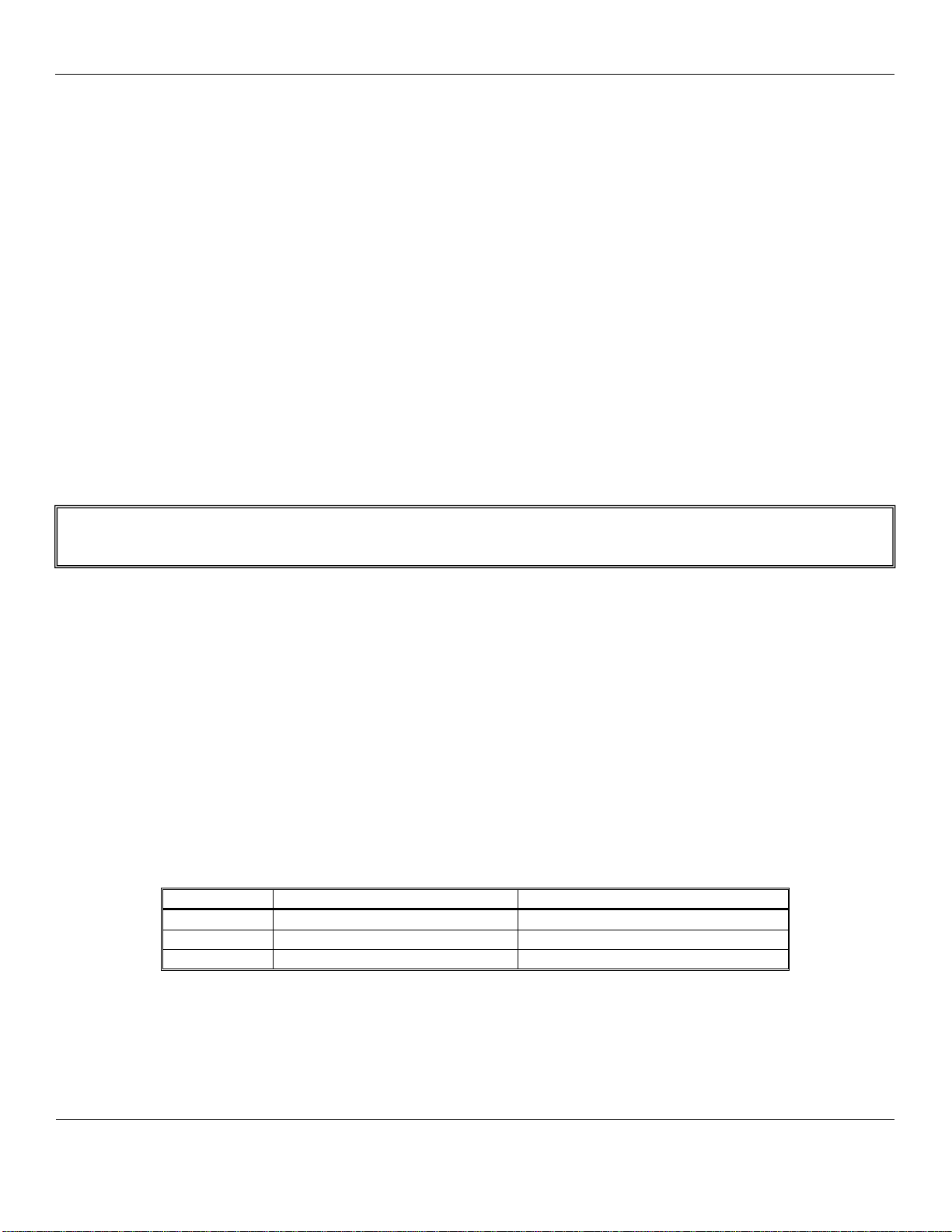
Table 2: Calibration Time
Sensor Type
Calibration Gas Concentration
Calibration Gas Application Time
MOS
PPM
3 – 4 minutes
MOS
% LEL
1 – 2 minutes
5.2.3 Exit Maintenance Menu
Exit maintenance, by tapping on the MENU switch until Exit appears on the display. Tap the SELECT switch to return to the
instrument Normal Gas Display.
N
OTE
:You can change the Calibration Gas Level. H
OLD
the magnet over the S
ELECT
switch for 2 – 4 seconds
The MENU switch changes digit indicated by underscore cursor
The SELECT switch locks underscored digit and moves to next digit

EX-5150
ENMET
Manual Revision Date – June 14, 2017
Page | 13
Manual Part No. – 80003-097
Normal Display Mode
OR
Zero
Cal OK
If the Zero signal is within Preset Specs the EX-5150-MOS will display
Cal OK, See Section 5.2.1
If the Zero signal is not within Preset Specs the EX-5150-MOS will
display Bad ZERO
N
OTE
:Some software revisions require the S
ELECT
switch be
tapped to accept the signal.
SELECT
M
ENU
Bad ZERO
PV: 0
SELECT
Tap the S
ELECT
switch to initiate Zero adjustment
mA Span
M
ENU
SELECT
100
To change mA Span set point:
Tap the M
ENU
switch until mA Span is displayed
Tap the S
ELECT
switch to display the set point
The M
ENU
switch changes digit indicated by underscore cursor
The S
ELECT
switch locks underscored digit and moves to next digit
To return to Normal Gas Display:
Tap M
ENU
switch until EXIT is displayed
Then tap S
ELECT
switch
Apply Calibration Gas until signal value becomes stable
(about 1 to 4 minutes) See Figure 4
If cal is good display will indicate OK or Same
If cal is not within preset “range” display will indicate
Bad Sens
N
OTE
:Some software revisions require the S
ELECT
switch
be tapped to accept the signal.
N
OTE
:You can change the Calibration Gas Level.
H
OLD
the magnet over the S
ELECT
switch
The M
ENU
switch changes digit indicated by underscore cursor
The S
ELECT
switch locks underscored digit and moves to next digit
See Section 5.2.2
SELECT
M
ENU
PV: 0
20
Cal OK
Same mV
Bad Sens
Span
SELECT
OR
OR
5ppm
M
ENU
H
OLD
the magnet over the M
ENU
switch for 2 – 4 seconds to
enter the Maintenance Menus
Exit
SELECT
Tap the S
ELECT
switch to return to the Normal Display
Mode.
See Section 5.2.3
M
ENU
Tap the magnet over the M
ENU
switch to cycle through Maintenance Menus
Select
Menu
To change Alarm set points:
Tap Menu switch until Alarm to be changed is displayed
Tap Select switch to display the set point
The M
ENU
switch: changes digit indicated by underscore cursor
The S
ELECT
switch: locks in the underscored digit and moves to
next digit
If change is not within range display returns to first digit
If change is within range display moves to Set Time Delay
Use M
ENU
and S
ELECT
switches as above to change time delay.
Between 0 and 5 seconds is allowed
If change is within range display moves to next menu
Λ- Indicates increasing alarm
V - Indicates decreasing alarm
SetTDsec
0
Alarm3
Λ50
M
ENU
SetTDsec
0
Alarm1
M
ENU
Λ10
SetTDsec
0
Alarm2
M
ENU
Λ20
Figure 5: EX-5150-MOS Maintenance Menu Flow Chart

EX-5150
ENMET
Manual Revision Date – June 14, 2017
Page | 14
Manual Part No. – 80003-097
5.3 Heater Voltage Settings
Heater Voltages are necessary for MOS sensors. They are preset at the factory and should not require field adjustment.
Do not adjust these voltages unless specifically instructed to do so by ENMETCorporation Technical Support Staff.
CAUTION:Improper adjustment of heater voltages can damage sensors voiding any warranties and also alter the operating
characteristics of the sensor in such a way that the EX-5150-MOS may not respond to it’s target gas.
5.4 Sensor Replacement
CAUTION:Area must be declassified during sensor replacement.
Sensors should be replaced when they can no longer be calibrated. Replacement sensor part numbers are listed in Section 6.0 of
this manual. If you do not know the proper part number for your sensor, be sure to have the EX-5150-MOS serial number
available when contacting your Distributor or ENMET Corporation Technical Support.
To replace a sensor, it is necessary to open the transmitter housing.
Remove the overlay and screws retaining the PC Board in the enclosure. Refer to Section 3.2, Figure 3.
Remove the sensor connector J8 and sensor
Wire in the new sensor. Refer to the wiring Table in Section 3.2, Figure 3.
After the new sensor has been installed, it is suggested to allow the sensor to stabilize for 24 hours.
A Factory calibration must be performed.
After entering the Maintenance menu, advance to the Zero menu. Then while viewing the Zero menu, hold the magnet over the
MENU switch for 2-4 seconds.
After 2-4 seconds, an F will appear on the far right hand side of the display. The F indicates that the instrument is in Factory
mode.
Perform the calibration Zero and Span procedures as outlined in Section 5.2. Be sure that the F is present when selecting the Zero
and Span functions.
The Factory calibration sets a calibration window for future standard instrument calibrations.
Only perform a factory calibration when installing a new sensor!!
6.0 Replacement Part Numbers
ENMET replacement part numbers:
Description
Part Number
For EX-5150-MOS p/n 10014-008
Sensor, 12
03033-812
Sensor, 13
03033-813
Sensor, 32
03032-832
Sensor, 19
03033-019
For EX-5150-MOS p/n 10014-009
Sensor, 1
03033-109
Regulator
03700-001
Overlay
06000-058
Magnet
50030-001
Calibration Gas, Consult ENMET Distributor or ENMET Corp.
NOTE:See Table 2 for sensor part number and calibration gas reference.
NOTE:See Figure 1 for location of marking on sensor.

EX-5150
ENMET
Manual Revision Date – June 14, 2017
Page | 15
Manual Part No. – 80003-097
Notes:

EX-5150
ENMET
Manual Revision Date – June 14, 2017
Page | 16
Manual Part No. – 80003-097
7.0 Terms and Conditions
7.1 Ordering Information
Address orders to: ENMET
Attention: Customer Service Department
680 Fairfield Court
Ann Arbor, MI 48108
Phone: 734-761-1270
Fax: 734-761-3220
You may also contact our customer service department by email info@enmet.com. MINIMUM ORDER IS $50.00.
7.2 Delivery
Unless Seller otherwise specifies, delivery will be made: FOB Ann Arbor, MI and/or FOB Bowling Green, KY. Title and risk of
loss shall pass to Buyer at that point. Shipping and handling charges will be Prepaid and Added to Buyer’s invoice. Buyer may
request shipping be charged to their own account with a preferred carrier. Seller shall have the right to choose means of
transportation and to route shipment when specific instructions are not included with Buyer’s order. Seller agrees to deliver the
goods and services, within the time, in accordance with specifications, at the prices specified on the face hereof. Buyer’s orders to
this quotation are not subject to cancellation or deferment of delivery without indemnification of loss to the Seller resulting there
from. Seller shall not be liable to Buyer for any loss or damage sustained on account of this delay or nonperformance due to
causes beyond Seller’s control and without his fault or negligence. Where performance of the terms here is contingent upon timely
delivery of goods or services by the Buyer and such delivery is in default, Seller shall be indemnified for any damage or loss
resulting there from, and/or by extension of Seller’s delivery commitment, as applicable.
7.3 Payment Terms
Payment Terms are Net 30 Days from the date of shipment from Seller unless otherwise noted. All shipping and handling costs
will be charged to Buyer on a Prepaid and Add basis. Buyer has the option of paying for shipping by charging its own account
with a carrier
7.4 Warranty Information and Guidelines
The Seller warrants new instruments to be free from defects in workmanship and material under normal use for a period of one
year from date of shipment. The warrant covers both parts and labor excluding calibration and expendable parts such as filters,
detector tubes, batteries, etc. If the inspection by the Seller confirms that the product is defective, it will be repaired or replaced at
no charge, within the stated limitations, and returned prepaid to any location in the United States. The Seller shall not be liable for
any loss or damage caused by the improper use or installation of the product. The Buyer indemnifies and saves harmless the Seller
with respect to any loss or damages that may arise through the use by the Buyer or others of this equipment. This warranty is
expressly given in lieu of all other warranties, either expressed, implied or statutory, including that of merchantability, and all
other obligations, or liabilities of ENMET, LLC for damages arising out of or in connection with the use or repair or performance
of the product. In no event shall ENMET, LLC, be liable for any indirect, incidental, special or consequential damages or for any
delay in the performance by ENMET, LLC, which may arise in connection with this equipment. ENMET neither assumes nor
authorizes any representatives or other persons to assume for it any obligation or liability other than that which is set forth herein.
Buyer agrees to indemnify and save harmless Seller for any damage or loss from lawsuits against Seller by reason of manufacture
of sale of materials, parts, or use of processes resulting from Buyer’s design specifications. Any patent, design, pattern, tool, die,
jig, fixture, drawing, test equipment, or process furnished by Seller; whether possessed by the Seller before the date of this
quotation, or devised or acquired by Seller during performance of the terms of this quotation, shall remain the property of the
Seller except by specific stipulation on the face hereof. Seller reserves the right, without liability, for damage or loss, to destroy
Buyer’s drawings, specifications, patterns and special tools supplied by Buyer for performance of the terms on the face hereof,
unless Buyer gives notice of the disposition of such items.
7.5 Return Policy
All returns for credit must be approved in advance by ENMET, LLC. Such returns are subject to a minimum $50.00 or 20%
restocking charge, whichever is greater. Approval of equipment for return is totally at the discretion of ENMET, LLC. All
requests for return/exchange must be made no later 30 days of the original shipping date from ENMET. The actual amount of any
resulting credit will not be determined prior to a complete inspection of the equipment by ENMET. Calibration gas cylinders
cannot be returned or restocked.

EX-5150
ENMET
Manual Revision Date – June 14, 2017
Page | 17
Manual Part No. – 80003-097
8.0 Instructions for Returning an Instrument for Service
Contact the ENMET Service Department for all service requests.
Phone: 734-761-1270
Email: rep[email protected]
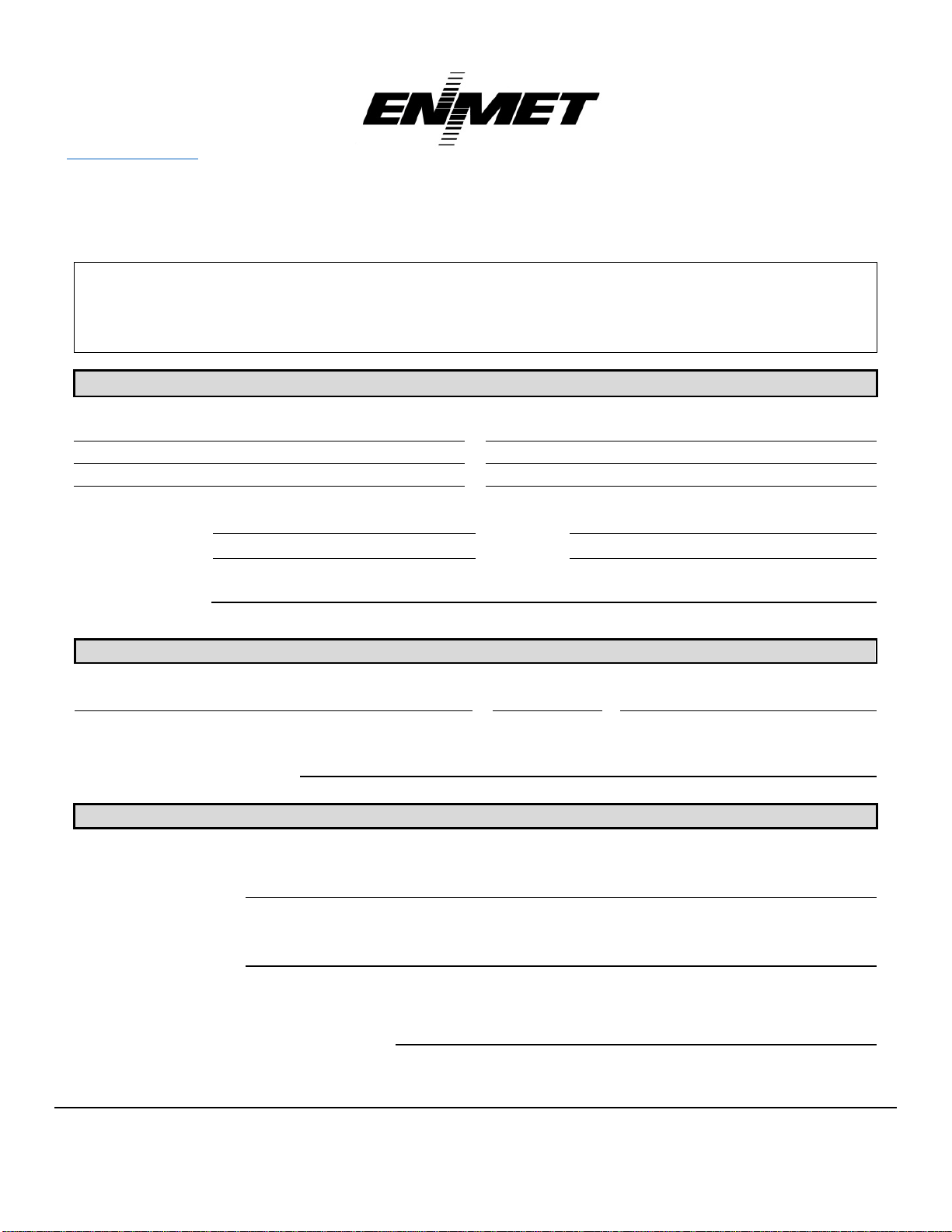
Fill out the “Service Request Form” found at the end of this manual and return with your instrument for all needs. Please send your
instrument for service to the site in which the product was purchased. A new “Service Request Form” may be requested if the one
found in the manual is not available. All instruments should be shipped prepaid to ENMET.
Address for Service:
Michigan Location: ENMET
Attention: Service Department
680 Fairfield Court
Ann Arbor, MI 48108
Kentucky Location: ENMET
62 Corporate Court
Bowling Green, KY 42103
Providing the “Service Request Form” assists in the expedient service and return of your unit and failure
to provide this information can result in processing delays. ENMET charges a one hour minimum billing for all approved repairs with
additional time billed to the closest tenth of an hour. All instruments sent to ENMET are subject to a minimum evaluation fee, even if
returned unrepaired. Unclaimed instruments that ENMET has received without appropriate paperwork or attempts to advise repair
costs that have been unanswered after a period of 60 days may, be disposed of or returned unrepaired COD and the customer will be
expected to pay the evaluation fee. Serviced instruments are returned by UPS/FedEx Ground and are not insured unless otherwise
specified. If expedited shipping methods or insurance is required, it must be stated in your paperwork.
NOTE: Warranty of customer installed components.
For Warranty Repairs, please reference ENMET’s “Warranty Information and Guidelines” (found earlier in this section).
Mailing/Shipping Address:
ENMET
680 Fairfield Court
Ann Arbor, MI 48108
Phone: 734.761.1270
Fax: 734.761.3220
ENMET
Rev.2 – 9/15/2016
Service Request Form
Service Request Form
PAYMENT METHOD
☐COD
☐VISA/MasterCard
☐American Express
Card Number
Exp. Date
Security Code:
Name as it Appears on
Card:
RETURN SHIPPING METHOD
☐
UPS Ground
☐
UPS 3 Day
Select
☐
UPS Next Day
Air
☐
UPS ND Air
Saver
☐
UPS 2 Day Air
UPS Account #:
☐
FedEx Ground
☐
FedEx Air
Express Saver
☐
FedEx Air
Overnight Std.
☐
FedEx Air 2
Day
☐
FedEx Air
Overnight P-1
FedEx Account #:
Insure Shipment:
☐
Yes
☐
No
Insurance
Amount:
$
Product Name or Number:
Product Serial Number:
Describe Problem or Needed Service:
Warranty Claim?
☐
Yes
☐
No
CUSTOMER INFORMATION
Billing Address:
Shipping Address:
Contact Name:
Phone #:
Email:
Fax #:
PO/Reference
#:
Table of contents
Other ENMET Transmitter manuals


Popular Transmitter manuals by other brands


RKI Instruments
RKI Instruments 65-2395RK-CH4 Operator's manual

AVGear
AVGear AVG-HDWP70TX-B user manual

Siemens
Siemens SITRANS T Series Compact operating instructions

Endress+Hauser
Endress+Hauser Liquisys M CUM223 operating instructions

Artel
Artel FiberLink 4160 Series Installation and operation manual

Dwyer Instruments
Dwyer Instruments 650 Series Specifications-installation and operating instructions


