Novalynx 225-RHP-2S Series User manual
DOC 225-RHP-2Sxx UM 20210113
225-RHP-2Sxx
User Manual
225-RHP-2S11 (4-20 mA output)
225-RHP-2S33 (0-5 V output)
Temperature and Relative Humidity Transmitter
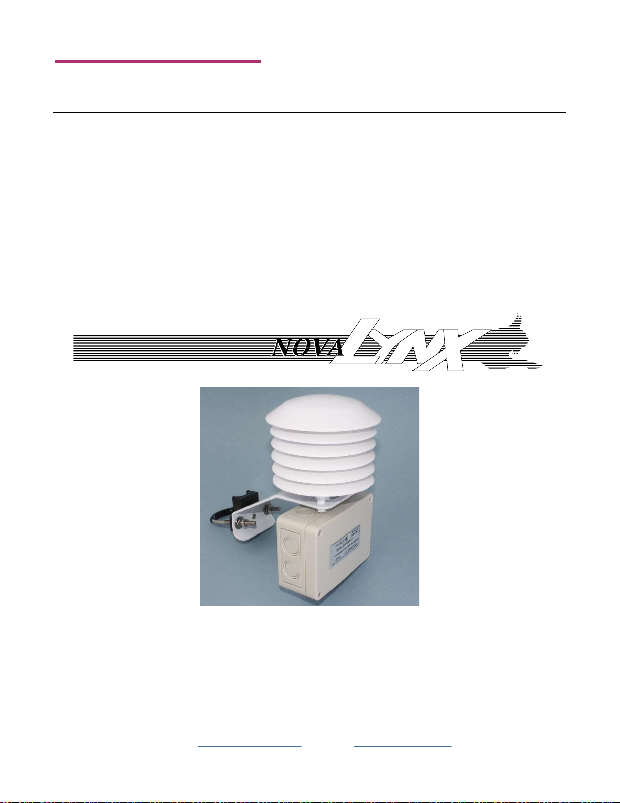
225-RHP-2Sxx Transmitter
with
380-RHRS Solar Radiation Shield
Phone (530) 823-7185
Email nova@novalynx.com Website www.novalynx.com

NovaLynx Corporation
225-RHP-2Sxx Page 2 January 2021
Receiving and Unpacking
Carefully unpack all components and compare to the packing list. Notify NovaLynx Corporation
immediately concerning any discrepancy. Inspect equipment to detect any damage that may have
occurred during shipment. In the event of damage, any claim for loss must be filed immediately with
the carrier by the consignee. Damages to equipment sent via Parcel Post or UPS require the consignee
to contact NovaLynx Corporation for instructions.
Returns
If equipment is to be returned to the factory for any reason, call NovaLynx between 8:00 a.m. and 4:00
p.m. Pacific Time to request a Return Authorization Number (RA#). Include with the returned
equipment a description of the problem and the name, address, and daytime phone number of the
sender. Carefully pack the equipment to prevent damage or additional damage during the return
shipment. Call NovaLynx for packing instructions in the case of delicate or sensitive items. If packing
facilities are not available take the equipment to the nearest Post Office, UPS, or other freight service
and obtain assistance with the packaging. Please write the RA# on the outside of the box.
Warranty
NovaLynx Corporation warrants that its products are free from defects in material and workmanship
under normal use and service for a period of one year from the date of shipment from the factory.
NovaLynx Corporation's obligations under this warranty are limited to, at NovaLynx's option: (i)
replacing; or (ii) repairing; any product determined to be defective. In no case shall NovaLynx
Corporation's liability exceed product's original purchase price. This warranty does not apply to any
equipment that has been repaired or altered, except by NovaLynx Corporation, or that has been
subjected to misuse, negligence, or accident. It is expressly agreed that this warranty will be in lieu of
all warranties of fitness and in lieu of the warranty of merchantability.
Address
NovaLynx Corporation
431 Crown Point Circle, Suite 120
Grass Valley, CA 95945-9531 USA
Phone: (530) 823-7185
Email: nova@novalynx.com
Website: www.novalynx.com
Copyright © 1988-2021 by NovaLynx Corporation

NovaLynx Corporation
225-RHP-2Sxx Page 3 January 2021
CONTENTS
1 FORWARD ....................................................................................................................................................................... 4
2 INTRODUCTION ............................................................................................................................................................... 4
3 PRECAUTIONS ................................................................................................................................................................. 4
4 SPECIFICATIONS .............................................................................................................................................................. 5
5 INSTALLATION ................................................................................................................................................................. 5
5.1 Outdoors ................................................................................................................................................................. 5
5.2 Indoors .................................................................................................................................................................... 5
5.3 Duct Mount ............................................................................................................................................................. 5
6 WIRING ............................................................................................................................................................................ 6
6.1 Dual 4-20 mA Output Wiring (Model 225-RHP-2S11) ............................................................................................. 6
6.2 Dual 0-5 V Output Wiring (Model 225-RHP-2S33) .................................................................................................. 6
7 TROUBLESHOOTING ........................................................................................................................................................ 7
7.1 Troubleshooting 4-20 mA Models .......................................................................................................................... 7
7.2 Troubleshooting 0-5 V Output Models: .................................................................................................................. 7
7.3 Determining the Source of a Failure ....................................................................................................................... 7
8 MAINTENANCE ................................................................................................................................................................ 8

NovaLynx Corporation
225-RHP-2Sxx Page 4 January 2021
1 FORWARD
Thank you for purchasing NovaLynx products. NovaLynx has been designing and manufacturing
weather instruments since 1988. NovaLynx represents several well-known brands of quality
manufacturers, including Gill Instruments, RM Young, Kipp & Zonen, and Vaisala. It is our hope that our
products will meet all your monitoring requirements.
2 INTRODUCTION
The 225-RHP-2Sxx Temperature and Relative Humidity Transmitters are highly accurate and easy to
use. The polymer capacitance humidity sensor is not affected by condensation, fog, high humidity, or
contaminants. A membrane filter protects both the humidity sensor and the solid state temperature
sensor.
The sensor can be used indoors for HVAC monitoring purposes. An optional solar radiation shield
(NovaLynx 380-RHRS) protects the sensor from rain and radiated heat when installed outdoors.
The weatherproof enclosure, cord grip cable entry point, and a filter protect the electronics and sensors
from environmental or mechanical damage. The mounting bracket fits 3/4" to 1-1/2" iron pipe.
The 225-RHP-2S11 has 4-20 mA loop powered outputs.
The 225-RHP-2S33 requires a power supply and outputs 0-5 volt signals
Cable is not included but may be ordered by the foot.
Recommended cable: NovaLynx 330-0524 (24 AWG, 5-conductor, shielded, with PVC jacket)
3 PRECAUTIONS
WARNING – Disconnect the supply before installation to prevent electrical shock and equipment
damage. Follow electrical code requirements.
CAUTION – Use electrostatic discharge precautions (e.g., use of wrist straps) during installation and wiring to
prevent equipment damage.
CAUTION – Do not exceed ratings of this device, permanent damage not covered by warranty may result. The
4-20 mA models are not designed for AC voltage operation.

NovaLynx Corporation
225-RHP-2Sxx Page 5 January 2021
4 SPECIFICATIONS
5 INSTALLATION
5.1 Outdoors
For outdoor applications, use the U-bolt to clamp the sensor to a vertical pipe up to 1 ½" (38mm) in
diameter. The 380-RHRS Solar Radiation Shield must be in place to protect the tip of the probe from
rain or sunshine. Remove the cover of the enclosure, then route your cable through the cord grip on
the bottom of the enclosure. Follow the wiring diagram to make the connections to the screw terminal
block, then tighten the cord grip, leaving some slack inside. Use cable ties to secure the cable to the
support pipe. Complete the installation by connecting to your monitoring system.
5.2 Indoors
The sensor may be mounted indoors without a solar radiation shield. It should be mounted in a
location that receives adequate air flow for proper operation. The transmitter should be mounted such
that the cord grip points down to prevent moisture from entering. The U-bolt can be removed and the
mounting bracket bolted to a wall or post.
5.3 Duct Mount
The tip of the probe is sometimes inserted into an HVAC duct. In this application, drill a 1" diameter
hole in the duct at the desired location (away from fans, corners, heating and cooling coils, and other
equipment that will affect the measurement of the relative humidity). Insert the probe until the
225-RHP-2Sxx Temperature and Relative Humidity Sensor
Relative Humidity Range 0 to 100% RH
Temperature Range -40 to 140°F (-40 to 60°C)
Accuracy, RH ±2% 10 to 90% RH @ 25°C
Accuracy, Temperature ±0.9°F @ 72°F (±0.3°C @ 25°C)
Hysteresis ±1%
Repeatability ±0.1% typical
Temperature Limits -40 to 140°F (-40 to 60°C)
Storage Temperature -40 to 176°F (-40 to 80°C)
Compensated Temperature Range -4 to 140°F (-20 to 60°C)
225-RHP-2S11
: 10 to 35 VDC; Output signal: 4 to 20 mA (loop powered).
225-RHP-2S33
: 15 to 35 VDC or 15 to 29 VAC; Output signal: 0 to 5 V @ 5 mA max.
Response Time 15 seconds
Electrical Connections Removable screw terminal block
Drift <1% RH/year
RH Sensor Capacitance polymer
Temperature Sensor Solid state band gap
Enclosure / Rating Polycarbonate / NEMA 4X (IP65)
Cable not included
Transmitter only: 1 lb (.45 kg) / 2 lbs (.9 kg)
Transmitter and Solar Radiation Shield: 2 lbs (.9 kg) / 3 lbs (1.4 kg)
Agency Approvals CE
Power Requirements
Weight / Shipping

NovaLynx Corporation
225-RHP-2Sxx Page 6 January 2021
mounting flange is flush to the duct. Run one or two straps (or long cable ties) around the duct to hold
the enclosure in place.
6 WIRING
6.1 Dual 4-20 mA Output Wiring (Model 225-RHP-2S11)
Dual 4-20 mA output units may be powered with a 10-35 VDC supply. The transmitter is designed as a
2-wire 4-20 mA device with two channels. The channels are common on the positive side of the current
loop. Sensor excitation power is derived from the RH channel, so power must always be applied to that
channel. If the temperature channel is not used, it can be left disconnected.
Note: If the RH output is not required, wire the “-” terminal of the power supply to terminal 1.
6.2 Dual 0-5 V Output Wiring (Model 225-RHP-2S33)
Dual 0-5 V units may be powered with 15-35 VDC or 15-29 VAC. Note polarity when using DC power.
The channels are common on the negative side. If desired, the RH or temperature output may be used
by itself.

NovaLynx Corporation
225-RHP-2Sxx Page 7 January 2021
7 TROUBLESHOOTING
If the sensor’s output signal appears to be in error or is absent, check the power connections. At the
sensor cable, measure the battery or the input power source voltage with a voltmeter. Be sure that the
instrument has been powered up correctly or wait for the next power ON cycle to occur. Check any
batteries to be sure that they have sufficient charge and an adequate voltage level to power the
instrument and that all connections are secure. Inspect the battery terminals to ensure that they are
clean and solidly connected to the battery.
7.1 Troubleshooting 4-20 mA Models
Verify appropriate supply voltage. The transmitter requires a minimum of 10 and a maximum of 35
VDC at its connection for proper operation. Choose a power supply with a voltage and current rating
which meets this requirement under all operating conditions. If the power supply is unregulated, make
sure voltage remains within these limits under all power line conditions. Ripple on the supply should
not exceed 100 mV.
Loop Resistance – The maximum allowable loop resistance depends on the power supply voltage.
Maximum loop voltage drop must not reduce the transmitter voltage below the 10 VDC minimum.
Maximum loop resistance can be calculated with the following equation. Vps is the power supply
voltage.
Some receivers, particularly loop powered indicators, may maintain a fixed loop voltage to power the
device. This voltage drop must also be subtracted from the power supply voltage when calculating the
voltage margin for the transmitter. The following equation takes this into account. Vrec is the receiver
fixed voltage.
7.2 Troubleshooting 0-5 V Output Models:
Verify appropriate supply voltage. The 0-5 V output requires a DC supply of 15-35 V or an AC supply of
15-29 V for proper operation maximum. Maximum output load is 5 mA.
7.3 Determining the Source of a Failure
The sensor is one part of the measurement system, and it is possible that the logger or PLC that the
sensor is being used with is actually the cause of a problem. If the problem cannot be located using the

NovaLynx Corporation
225-RHP-2Sxx Page 8 January 2021
techniques above, then disconnect the Temperature/Humidity sensor from the monitoring system and
test it independently, using a power source and a digital voltmeter.
Refer to the appropriate wiring diagram (Section 6) and set up your meter to read either mA or volts
accordingly. Supply power to the transmitter circuit board and then measure the output of the board.
Take note of the reading, then try to vary the reading.
To increase the humidity reading, breathe on the humidity sensor while watching for a change
in the meter reading. The change may take 10 to 40 seconds.
To increase the temperature reading, hold the probe in your hand for several seconds.
If no change is observed, unscrew the filter from the top of the probe and try again.
8 MAINTENANCE
No routine maintenance is required; however, a periodic check of the system calibration is
recommended. The Series RHP is not field serviceable and should be returned if repair is needed (field
repair should not be attempted and may void the warranty). Be sure to include a brief description of
the problem plus any relevant application notes. Contact customer service to receive a return goods
authorization number before shipping.
This manual suits for next models
2
Table of contents


