Numark C3 User manual

QUICKSTART GUIDE
ENGLISH ( 3 – 6 )
MANUAL DE INICIO RÁPIDO
ESPAÑOL ( 7 – 10 )
GUIDE D’UTILISATION RAPIDE
FRANÇAIS ( 11 – 14 )
MANUALE RAPIDO DI UTILIZZAZIONE
ITALIANO ( 15 – 18 )
KURZANLEITUNG
DEUTSCH ( 19 – 22 )


3
INTRODUCTION
Welcome to the C3 – a professional 19”, 5-channel rack mixer. Here are a few of the features you’ll come to love about this
device:
5 channels plus DJ mic control with EQ
10 line, 3 phono, and 3 mic inputs
Master balanced XLR outputs with Record and Zone outputs
Steep 3-band EQ on every channel
Split or blend cueing, plus PFL gain adjust with meter
Fader start capability
Panning for master output
Replaceable assignable crossfader
We hope that the C3 serves you well for many years to come.
Sincerely,
The People of Numark
BOX CONTENTS
C3
IEC Power Cable
Quickstart Guide
Safety & Warranty Information Booklet
REGISTRATION
Please go to http://www.numark.com to register your C3. Registering your product ensures that we can keep you up-to-date
with any last-minute product developments and provide you with world-class technical support, should you run into any
problems.
GROUND RULES
1. Make sure all items listed in the BOX CONTENTS section are included in the box.
2. READ SAFETY & WARRANTY INFORMATION BOOKLET BEFORE USING THE PRODUCT.
3. Study the connection diagram in this guide.
4. Place mixer in an appropriate position for operation.
5. Make sure all devices are turned off and all faders and gain knobs are set to “zero.”
6. Connect all stereo input sources as indicated in the diagram.
7. Connect the stereo outputs to power amplifier(s), tape decks, and/or other audio sources.
8. Plug all devices into AC power.
9. Switch everything on in the following order:
•Audio input sources (i.e. turntables, CD players, etc.)
•Mixer
•Last, any amplifiers or output devices
10. When turning off, always reverse this operation by:
•Turning off amplifiers
•Mixer
•Last, any input devices

4
NORMAL
FILTERS
FLANGER
AUTOPAN
LR
AUTOCUT
FILTERED
LOPASS
VARI-CUT
RATE
RATE
OR
CONNECTION DIAGRAM
MICROPHONES
HEADPHONES
DVD PLAYER
CD PLAYER
CD PLAYER CD PLAYER
TURNTABLE TURNTABLE TURNTABLE
HOUSE AMP
BOOTH AMP
CD BURNER
TAPE DECK
DUAL CD PLAYER
REMOTE MIXER
OR
OR

5
REAR PANEL FEATURES
111
22 2
33
33
3333
44
33
5
678
9
10
11
12
1. PHONO INPUTS (RCA) – Connect phono-level devices, such as turntables, to these inputs.
2. GROUNDING TERMINAL – If you are using phono-level turntables with a grounding wire, connect the grounding wire to
these terminals. If you experience a low “hum” or “buzz”, this could mean that your turntables are not grounded.
Note: Some turntables have a grounding wire built into the RCA connection and, therefore, nothing needs to be
connected to the grounding terminal.
3. LINE INPUTS (RCA) –Connect line-level devices, such as CD players, samplers or audio interfaces, to these inputs.
4. MIC INPUTS – Connect ¼” microphones to these inputs.
5. FADER START – If you would like to use the mixer’s fader-start to automatically start and cue music from external
devices via the crossfader, connect these outputs to your fader-start compatible device. You can use standard 1/8”
stereo cables to make these connections.
6. ZONE OUTPUT (RCA) – Connect this output to an external monitoring device, such as a PA system, powered monitors,
or a home stereo. The level of this output with the ZONE knob on the top panel.
7. RECORD OUTPUT (RCA) – Use standard RCA cables to connect this output to a recording device, such as a CD
recorder or tape deck. The level of this output is based upon pre-master levels.
8. MASTER OUTPUT (RCA) – Use standard RCA cables to connect this output to a speaker or amplifier system. The
level of this output is controlled by the MASTER knob on the top panel.
9. MASTER OUTPUT (BALANCED) – Use XLR cables to connect this Master output to a speaker or amplifier system.
The level of this output is controlled by the Master knob on the top panel.
10. POWER IN – Use the included power cable to connect the mixer to a power outlet. While the power is switched off, plug
the power supply into the mixer first, then plug the power supply into a power outlet.
11. VOLTAGE SELECTOR – This 2-position switch sets the AC input voltage for the speaker. U.S. users should set this
switch to “100-120V” whereas U.K. and most European users will need to set this to “220-240V”.
12. POWER SWITCH – Turns the mixer on and off. Turn on the mixer after all input devices have been connected and
before you turn on amplifiers. Turn off amplifiers before you turn off the mixer.

6
TOP PANEL FEATURES
1
2
3
4
5
67
8
9
10
7
8
9
10
7
8
9
10
18 19
19 20
20
7
8
9
10
7
8
9
10
11
12
13
11
12
13
11
12
13
11
12
13
11
12
13
14
21 22
23
24
25 25
26
15
16
17
1. POWER LED – Illuminates when the mixer is on.
2. MIC ON/OFF – Turns the microphone input on or off.
3. MIC GAIN – Adjusts the audio level of the microphone signal.
4. MIC BASS – Adjusts the low (bass) frequencies of the microphone channel.
5. MIC TREBLE – Adjusts the high (treble) frequencies of the microphone channel.
Tip: If you experience feedback when using a microphone at loud levels, try turning down the high frequencies.
6. MIC INPUT – Connect a microphone to this input with an XLR or ¼” cable.
7. CHANNEL GAIN – Adjusts the corresponding channel’s pre-fader and pre-EQ gain level.
8. CHANNEL TREBLE – Adjusts the high (treble) frequencies of the audio on the corresponding channel.
9. CHANNEL MID – Adjusts the mid-range frequencies of the audio on the corresponding channel.
10. CHANNEL BASS – Adjusts the low (bass) frequencies of the audio on the corresponding channel.
11. INPUT SELECTOR – Selects the input source to be routed to the corresponding channel. Input jacks are located on the
rear panel.
12. CHANNEL FADER – Adjusts the audio level on the corresponding channel.
13. PFL –Sends pre-fader, pre-EQ audio of the corresponding channel to the Cue channel for headphone monitoring.
14. CUE GAIN – Adjusts the audio level of the Cue channel.
15. CUE BLEND – Slide this to mix the Cue channel and Program mix in the headphones. When all the way to the left, only
channels routed to the Cue channel will be heard. When all the way right, only the Program mix will be heard.
16. BLEND / SPLIT – When pressed, this button sends all audio in the Cue channel to the left side of the headphones and
the Program mix to the right side of the headphones. When raised, you may control the balance of the Cue channel and
Program mix with the CUE BLEND fader (see #15).
17. HEADPHONES – Connect your ¼” headphones to this output for cueing and mix monitoring.
18. CROSSFADER – Blends audio between the channels assigned to the left and right side of the crossfader (see #19).
Note: The crossfader is user-replaceable if it should ever wear out. Simply remove the facepanel, then remove the
screws holding it in position. Replace the fader with a quality authorized replacement from your local Numark retailer
only.
19. CROSSFADER ASSIGN – Selects which input channel will be heard when the crossfader is moved towards this knob.
All channels not assigned will remain active.
20. FADER START – Enables or disables “fader start” on the corresponding side of the crossfader. When fader start is
enabled on one side, moving the crossfader toward that side will cause any fader start-compatible device (connected to
the FADER START output on the rear panel) to start playing.
21. MASTER FADER – This control adjusts the output volume of the Program mix.
22. STEREO / MONO – Adjusts the Program mix for stereo or mono operation.
23. BALANCE – Adjusts the balance of right to left audio in all outputs (MASTER, RECORD, and ZONE OUTPUTS).
24. METER MODE – Determines whether audio from the Program mix or the Cue channel is sent to the STEREO LEVEL
INDICATOR.
25. STEREO LEVEL INDICATOR – Monitors the audio level of the Master output or Cue Channel, depending on the
position of the METER MODE button.
26. ZONE – Controls the audio level of the RECORD and ZONE OUTPUTS.
Tip: The RECORD and ZONE OUTPUTS can be used to supply line-level audio to a lighting controller or sound-
activated lighting system.

7
INTRODUCCIÓN
Bienvenido al C3 — el mezclador profesional para rack de 5 canales y 19 pulgadas. He aquí algunas de las características de
este dispositivo que seguramente le encantarán:
5 canales más control de micrófono de DJ con ecualización
10 entradas de línea, 3 fonográficas y 3 de micrófono
Salidas maestras XLR balanceadas con salidas para grabación y zona
Excelente ecualizador de 3 bandas en todos los canales
Búsqueda de punto inicial (cue) de división y combinación, más ajuste de ganancia PFL con medidor
Capacidad de Fader start
Paneo de la salida maestra
Crossfader asignable reemplazable
Esperamos que el C3 le brinde un buen servicio por muchos años.
Atentamente,
La Gente de Numark
CONTENIDO DE LA CAJA
C3
Cable de alimentación IEC
Guía de inicio rápido
Folleto de información sobre la seguridad y la garantía
REGISTRO
Visite http://www.numark.com y registre su C3. El registro de su producto asegura que podamos mantenerle actualizado con
los desarrollos de productos de último momento y brindarle apoyo técnico de categoría mundial en caso de que tenga algún
problema.
REGLAS BÁSICAS
1. Asegúrese de que todos los artículos indicados en “Contenido de la caja" estén incluidos en la caja.
2. LEA EL FOLLETO DE INFORMACIÓN SOBRE LA SEGURIDAD Y LA GARANTÍA ANTES DE UTILIZAR EL
PRODUCTO.
3. Estudie el diagrama de conexión incluido en esta guía.
4. Coloque el mezclador en una posición adecuada para su funcionamiento.
5. Asegúrese que todos los dispositivos estén apagados y que todos los faders y perillas de ganancia estén en posición
«cero».
6. Conecte todas las fuentes de entrada estéreo como se indica en el diagrama.
7. Conecte las salidas estéreo a los amplificadores de potencia, bandejas de cinta magnética y/o otras fuentes de audio.
8. Enchufe todos los dispositivos al suministro de corriente alterna.
9. Encienda todo en el siguiente orden:
•fuentes de entrada de audio (por ejemplo, giradiscos, reproductores de CD, etc.)
•el mezclador
•por último, cualquier amplificador o dispositivo de salida
10. Al apagar, realice siempre esta operación en sentido inverso:
•apague los amplificadores
•el mezclador
•por último, cualquier dispositivo de entrada

8
NORMAL
FILTERS
FLANGER
AUTOPAN
LR
AUTOCUT
FILTERED
LOPASS
VARI-CUT
RATE
RATE
OR
DIAGRAMA DE CONEXIÓN
MICRÓFONO
AURICULARES
REPRODUCTOR
DE DVD
REPRODUCTOR
DE CD
GIRADISCOS GIRADISCOS GIRADISCOS
AMPLIFICADOR DE AUDITORIO
AMPLIFICADOR DE CABIN
A
GRABADORA
DE CD
CINTA DE
CASSETTE
REPRODUCTOR
DE CD DUAL
MEZCLADOR
REMOTO
O
O
REPRODUCTOR
DE CD
REPRODUCTOR
DE CD

9
CARACTERÍSTICAS DEL PANEL TRASERO
111
22 2
33
33
3333
44
33
5
678
9
10
11
12
1. ENTRADAS FONOGRÁFICAS (RCA) – Estas entradas se usan para conectar dispositivos de nivel fonográfico, como
giradiscos.
2. TERMINAL DE TIERRA – Si usa giradiscos de nivel fonográfico con cable de conexión a tierra, asegúrese de conectar
dicho cable a estos terminales. Si se experimenta un zumbido grave, puede significar que sus giradiscos no están
conectados a tierra.
Nota: Algunos giradiscos tienen el cable de conexión a tierra incorporado a la conexión RCA y, por lo tanto, no es
necesario conectar nada al terminal de tierra.
3. ENTRADAS DE LÍNEA – Estas entradas se usan para conectar dispositivos de nivel de línea, tales como reproductores
de CD, muestreadores o interfaces de audio.
4. ENTRADA DE MICRÓFONO – Conecte un micrófono de 1/4” a esta entrada. Los controles de micrófono se
encuentran en el panel superior.
5. FADER START – Si desea usar el fader-start del mezclador para iniciar y buscar automáticamente el punto inicial de
música de dispositivos externos a través del crossfader del mismo, conecte estas salidas a su dispositivo compatible
con fader-start. Puede usar cables estéreo estándar 1/8” para efectuar estas conexiones.
6. SALIDA DE ZONA (RCA) – Esta salida sirve para conectar a un dispositivo de monitoreo externo como un sistema de
megafonía, monitores alimentados o un estéreo hogareño. El nivel de esta salida se controla con la perilla ZONE del
panel superior.
7. SALIDA PARA GRABACIÓN (RCA) – Use cables RCA estándar para conectar esta salida a un dispositivo de
grabación, tal como un grabador de CD o bandeja de cinta. El nivel de esta salida se basa en los niveles pre-master.
8. SALIDA MAESTRA (RCA) – Use cables RCA estándar para conectar esta salida maestra a un sistema de altavoces o
amplificador. El nivel de esta salida se controla con la perilla MASTER del panel superior.
9. SALIDA MAESTRA (BALANCEADA) – Esta salida XLR de baja impedancia sirve para conectar a un sistema de
megafonía o monitores alimentados. El nivel de esta salida se controla con el fader MASTER del panel superior.
10. ENTRADA DE ALIMENTACIÓN - Use el cable de alimentación incluido para conectar el mezclador a un tomacorriente
alimentado. Con la alimentación eléctrica desconectada, enchufe la fuente de alimentación al mezclador primero, y
luego al tomacorriente.
11. SELECTOR DE VOLTAJE – Este conmutador de 2 posiciones establece el voltaje de entrada de CA del altavoz. Los
usuarios de EE.UU. deben colocar este conmutador en “100-120V”, mientras que los del Reino Unido y la mayoría de
los países europeos deben colocarlo en “220-240V.”
12. INTERRUPTOR DE ENCENDIDO – Enciende y apaga el mezclador. Encienda el mezclador después de desconectar
todos los dispositivos de entrada y antes de encender los amplificadores. Apague los amplificadores antes de apagar el
mezclador.

10
CARACTERÍSTICAS DEL PANEL SUPERIOR
1
2
3
4
5
67
8
9
10
7
8
9
10
7
8
9
10
18 19
19 20
20
7
8
9
10
7
8
9
10
11
12
13
11
12
13
11
12
13
11
12
13
11
12
13
14
21 22
23
24
25 25
26
15
16
17
1. LED DE ENCENDIDO – Se ilumina cuando el mezclador está encendido.
2. MICRÓFONO SÍ/NO – Conecta y desconecta la entrada de micrófono.
3. GANANCIA DE MICRÓFONO – Ajusta el nivel de audio de la señal de micrófono.
4. GRAVES DE MICRÓFONO – Ajusta las bajas frecuencias (graves) del canal de micrófono.
5. AGUDOS DE MICRÓFONO – Ajusta las altas frecuencias (agudos) del canal de micrófono.
Consejo: Si experimenta realimentación cuando usa un micrófono con niveles altos, pruebe disminuyendo las altas
frecuencias.
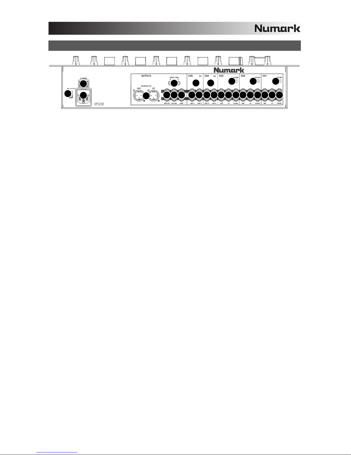
6. ENTRADA DE MICRÓFONO – Conecte a esta entrada un micrófono con un cable XLR o de 1/4”.
7. GANANCIA DE CANAL – Ajusta el nivel de ganancia preecualización y pre-fader del audio del canal.
8. TREBLE DE CANAL – Ajusta las altas frecuencias (agudos) del audio que se reproduce en el canal correspondiente.
9. MEDIOS DE CANAL – Ajusta las frecuencias medias del audio que se reproduce en el canal correspondiente.
10. GRAVES DE CANAL – Ajusta las bajas frecuencias (graves) del audio que se reproduce en el canal correspondiente.
11. SELECTOR DE ENTRADAS – Permite seleccionar la fuente de entrada que se aplica al canal correspondiente.
12. FADER DE CANAL – Ajusta el nivel de audio en el canal correspondiente.
13. PFL – Envía el audio pre-fader al canal de Cue para monitoreo con los auriculares.
14. GANANCIA DE CUE – Ajusta el nivel del audio del canal de cue.
15. COMBINACIÓN DE CUE – Deslice este control para mezclar los canales de cue y programa en los auriculares.
Cuando está en el extremo izquierdo, sólo se oyen los canales aplicados al canal de cue. Cuando se gira totalmente a
la derecha, se oye sólo la mezcla del programa.
16. COMBINAR / DIVIDIR – Cuando está pulsado, este botón envía todo el audio del canal de cue al lado izquierdo de los
auriculares y la mezcla de programa al lado derecho de los mismos. Cuando está levantado, es posible controlar el
balance del canal de cue y la mezcla de programa con el fader de combinación de cue.
17. AURICULARES – Conecte sus auriculares de ¼” a esta salida para búsqueda de punto inicial (cue) y monitoreo de la
mezcla.
18. CROSSFADER – Combina el audio entre los canales asignados a los lados izquierdo y derecho del crossfader.
Nota: El usuario puede reemplazar el crossfader en caso de que se desgaste. Simplemente, retire el panel frontal y
luego los tornillos que lo mantienen sujeto. Cambie el fader por un repuesto de calidad autorizado por su vendedor de
Numark más cercano.
19. ASIGNACIÓN DE CROSSFADER – Selecciona cuál canal de entrada se podrá escuchar cuando se mueve el
crossfader hacia esta perilla. Todos los canales no asignados permanecen activos.
20. FADER START – Activa o desactiva el “fader-start” del lado correspondiente del crossfader. Cuando el fader-start está
activado en un lado, el mover el crossfader hacia ese lado hace que cualquier dispositivo compatible con fader-start
(conectado a la salida de fader-start del panel trasero) comience a reproducir.
21. FADER MAESTRO – Ajusta el volumen de salida de la mezcla de programa.
22. ESTÉREO / MONO – Ajusta la mezcla de programa para operación estéreo o mono.
23. BALANCE – Ajusta el balance de audio derecho a izquierdo en todas las salidas (MAESTRA, PARA GRABACIÓN y
ZONA).
24. MODO DEL MEDIDOR – Determina si se envía al INDICADOR DE NIVEL ESTÉREO el audio de la mezcla de
programa o el canal de cue.
25. INDICADOR DE NIVEL ESTÉREO – Monitorea el nivel de audio de la salida de programa o el canal de cue, en función
de la posición del botón METER MODE (Modo del medidor).
26. ZONA – Ajusta el nivel de audio de las salidas para GRABACIÓN y ZONA.
Consejo: Las salidas para GRABACIÓN y ZONA se pueden utilizar también para suministrar audio de nivel de línea a
un controlador de iluminación o sistema de luces activadas por sonido.

11
INTRODUCTION
Voici la C3 – une console de mixage pour bâti électronique de 19 po à 5 canaux pour professionnels. Voyez ci-dessous
quelques-unes des caractéristiques que vous apprécierez de ce produit :
5 canaux plus commandes DJ MIC avec égalisation
Entrées : 10 ligne, 3 phono et 3 microphone
Sorties Master XLR symétriques avec sorties Record et Zone
Égalisation à 3 bandes sur tous les canaux
Fonction répartition/mixage, plus contrôle du gain PFL avec vumètre
Fonction Fader-start
Panoramique sur sortie Master
Crossfader assignable et remplaçable
Nous espérons que la console de mixage C3 vous servira bien pendant de nombreuses années.
Cordialement,
Toute l’équipe de Numark
CONTENU DE LA BOÎTE
C3
Câble d'alimentation CEI
Guide d'utilisation simplifié
Le livret des consignes de sécurité et des informations concernant la garantie
ENREGISTREMENT
Veuillez visiter le site internet http://www.numark.com pour enregistrer votre nouvelle C3. L'enregistrement des produits vous
permet d'être informé sur les toutes dernières nouveautés concernant les produits et de vous offrir un soutien technique de
niveau international, si vous en aviez besoin.
RÈGLES DE BASE
1. Assurez-vous que tous les articles énumérés dans le contenu de la boîte de ce guide sont inclus dans la boîte.
2. VEUILLEZ LIRE LE LIVRET DES CONSIGNES DE SÉCURITÉ ET DES INFORMATIONS SUR LA GARANTIE
AVANT D'UTILISER LE PRODUIT.
3. Examinez le schéma de connexion de ce guide.
4. Placez la console de mixage en position de fonctionnement.
5. Assurez-vous que tous les appareils sont hors tension et que tous les atténuateurs et le gain sont réglés à « zéro ».
6. Connectez toutes les sources d'entrées stéréo tel qu'indiqué sur le schéma.
7. Branchez toutes les sorties aux amplificateurs de puissance, aux lecteurs de cassette et aux sources audio.
8. Branchez tous les appareils à une prise de courant alternatif (AC).
9. Mettre tous les appareils sous tension dans l'ordre suivant.
•Sources d'entrée audio (c.-à-d.tourne-disques, lecteurs de disques compacts, etc.)
•Consoles de mixage
•En dernier, tous amplificateurs ou appareils de sortie
10. Pour mettre hors tension, toujours inverser l'opération :
•Éteindre les amplificateurs
•Consoles de mixage
•En dernier, tous les appareils d'entrée

12
NORMAL
FILTERS
FLANGER
AUTOPAN
LR
AUTOCUT
FILTERED
LOPASS
VARI-CUT
RATE
RATE
OR
SCHÉMA DE CONNEXION
MICROPHONES
ÉCOUTERS DJ
LECTEUR DVD
LECTEUR
LECTEUR LECTEUR
TABLE
TOURNANTE
AMP LOCAU
X
AMPLI CABINE
GRAVEUR CD
LECTEUR CASSETTES
LECTEUR CD DOUBLE
CONSOLE
OU
OU
TABLE
TOURNANTE
TABLE
TOURNANTE

13
CARACTÉRISTIQUES DU PANNEAU ARRIÈRE
111
22 2
33
33
3333
44
33
5
678
9
10
11
12
1. ENTRÉES PHONO (RCA) – Ces entrées permettent de brancher des appareils à niveau phono, tels que les tables
tournantes.
2. BORNE DE MISE À LA TERRE – Si vous utilisez des tables tournantes avec fils de mise à la terre, assurez-vous de
brancher le fils à cette borne. S’il y a un ronflement ou du bruit, il se pourrait que vos tables tournantes ne soient pas
mises à la terre.
Remarque: Certaines tables tournantes fabriquées récemment sont dotées d'un fil de mise à la terre intégré à la
connexion RCA, et donc, n'ont pas besoin d’être reliées à la borne de mise à la terre.
3. ENTRÉES LINE (RCA) – Ces entrées permettent de brancher des appareils à niveau ligne tels que lecteurs de disques
compacts, échantillonneurs ou autres interfaces audio.
4. ENTRÉE MIC – Permet de brancher un microphone ¼ po. Les commandes microphone sont situées sur le panneau
supérieur.
5. FADER START – Si vous désirez utiliser la fonction Fader Start de la console afin de lancer et arrêter la musique
provenant d’autres appareils à partir du crossfader de la console, branchez ces sorties aux appareils compatibles avec
cette fonction. Vous pouvez utiliser des câbles stéréo standards de 1/8 po pour faire ces raccordements.
6. SORTIE ZONE (RCA) – Cette sortie sert à connecter un système audio externe tel qu'un système de sonorisation, des
moniteurs amplifiés ou une stéréo maison. Le niveau du signal de cette sortie est commandé par le bouton ZONE du
panneau supérieur.
7. SORTIE RECORD (RCA) – Utilisez des câbles RCA standards afin de brancher cette sortie à un appareil
d’enregistrement tels qu’un lecteur de cassettes ou un graveur de CD. Le niveau de la sortie dépend des niveaux de
pré-mastérisation.
8. SORTIE MASTER (RCA) – Utilisez des câbles RCA standards afin de brancher cette sortie à un haut-parleur ou à un
système de sonorisation. Le niveau du signal de cette sortie est commandé par le bouton MASTER du panneau
supérieur.
9. SORTIE MASTER (SYMÉTRIQUE) – Ce connecteur XLR à basse impédance sert à connecter un système audio
externe tel qu'un système de sonorisation, des moniteurs amplifiés. Le niveau de sortie principale est commandé par le
potentiomètre MASTER sur le panneau supérieur.
10. POWER IN – Branchez le câble d’alimentation inclus pour brancher la console dans une prise d’alimentation murale.
Lorsque la console de mixage est hors tension, branchez le câble d'alimentation dans la console, puis dans la prise de
courant.
11. SÉLECTEUR DE TENSION – Ce sélecteur à deux positions règle la tension d’entrée CA pour le haut-parleur. Pour
l’Amérique du Nord, ce sélecteur doit être réglé sur « 100-120 V », alors que pour le Royaume Uni et la majeure partie
de l’Europe il doit être réglé sur « 220-240 V ».
12. L'INTERRUPTEUR D'ALIMENTATION – Met l’appareil sous et hors tension. Branchez la console après avoir branché
tous les appareils et avant de mettre les amplificateurs sous tension. Mettez les amplificateurs hors tension avant de
mettre la console de mixage hors tension.

14
CARACTÉRISTIQUES DU PANNEAU SUPÉRIEUR
1
2
3
4
5
67
8
9
10
7
8
9
10
7
8
9
10
18 19
19 20
20
7
8
9
10
7
8
9
10
11
12
13
11
12
13
11
12
13
11
12
13
11
12
13
14
21 22
23
24
25 25
26
15
16
17
1. DEL D’ALIMENTATION – S’allume lorsque la console de mixage est sous tension.
2. MIC ON/OFF – Permet d’activer ou de désactiver l’entrée microphone.
3. MIC GAIN – Permet d'ajuster le niveau du signal audio de l’entrée microphone.
4. MIC BASS – Permet d'ajuster le niveau des basses fréquences du canal microphone.
5. MIC TREBLE – Permet d'ajuster le niveau des hautes fréquences du canal microphone.
Conseil: Si vous entendez du feedback lorsque vous utilisez le microphone à de hauts niveaux, essayez de diminuer
les hautes fréquences.
6. ENTRÉE MIC – Permet de brancher un microphone à l’aide d’un câble XLR ou ¼ po.
7. GAIN DU CANAL – Permet d’ajuster le niveau du signal audio pré-atténuateur et pré-égalisation.
8. TREBLE DU CANAL – Permet d'ajuster le niveau des hautes fréquences du canal correspondant.
9. MID DU CANAL – Permet d'ajuster le niveau des fréquences moyennes de l’audio du canal correspondant.
10. BASS DU CANAL – Permet d'ajuster le niveau des basses fréquences de l’audio du canal correspondant.
11. SÉLECTEUR D’ENTRÉE – Ce réglage permet de sélectionner la source d’entrée qui est acheminée au canal
correspondant. Les entrées sont situées sur le panneau arrière.
12. CHANNEL FADER – Uilisez cet atténuateur pour ajuster le niveau de l’audio acheminé au Program mix.
13. PFL –Achemine le signal du canal correspondant, avant atténuation et égalisation, au canal de pré-écoute (casque).
14. CUE GAIN – Permet d’ajuster les niveaux du canal du casque d'écoute.
15. CUE BLEND – Permet de mixer le canal de pré-écoute et du Program mix dans le casque d’écoute. Lorsqu'il est
déplacé à l’extrémité gauche, seuls les canaux acheminés au casque d’écoute sont entendus. Lorsqu'il est déplacé à
l'extrémité droite, seul le mixe du programme est entendu.
16. BLEND / SPLIT – Appuyez sur le bouton afin d’acheminer tout l’audio assigné au canal de pré écoute (CUE) à
l’oreillette gauche du casque d’écoute et le Program mix à l’oreillette droite. Lorsqu’il n’est pas enfoncé, vous pouvez
régler la symétrie du canal de pré écoute et celle du Program mix à l’aide du potentiomètre Cue Blend.
17. CASQUE D’ÉCOUTE – Permet de brancher un casque d’écoute ¼ po pour la pré écoute.
18. CROSSFADER – Permet de mélanger l’audio entre les canaux assignés aux extrémités du Crossfader.
Remarque: Ce potentiomètre est remplaçable par l’utilisateur s’il devait se détériorer. Retirez tout simplement le
panneau avant et dévissez les vis qui le retiennent en position. Remplacez le potentiomètre avec un autre potentiomètre
de qualité autorisé provenant de votre détaillant Numark local.
19. ASSIGN – Permet de sélectionner lequel des canaux d’entrée sera utilisé lorsque le crossfader sera déplacé vers ce
bouton. Tous les canaux non assignés demeurent actifs.
20. FADER START – Permet d’activer ou de désactiver la fonction de Fader Start d’une des extrémités du crossfader.
Lorsque la fonction Fader Start est activée sur une des extrémités, déplacer le crossfader vers cette l’extrémité permet
d’activer tout appareil compatible avec cette fonction et branché à la sortie Fader Start du panneau arrière.
21. MASTER FADER – Ajuste les niveaux de la sortie du Program mix.
22. STEREO / MONO – Permet de régler le Program mix au mode stéréo ou mono.
23. BALANCE – Permet de régler l’équilibre entre les signaux droits et les signaux gauches de toutes les sorties (MASTER,
RECORD et ZONE).
24. METER MODE – Détermine lequel de l’audio du Program mix ou de la pré-écoute est acheminé à l’indicateur du niveau
stéréo.
25. INDICATEUR DU NIVEAU STÉRÉO – Indique le niveau stéréo de la sortie Master ou du canal de pré-écoute, selon la
position de la touche METER MODE.
26. ZONE – Permet de régler le niveau des sorties RECORD et ZONE.
Conseil: Les sorties RECORD et ZONE peuvent être utilisées afin de fournir un signal à niveau ligne à un contrôleur ou
système d’éclairage à activation sonore.

15
INTRODUZIONE
Benvenuti al C3, mixer da rack professionale a 5 canali da 19”. Ecco alcune delle funzioni di questo dispositivo che adorerete:
5 canali più comando mic DJ con EQ
10 ingressi di linea, 3 ingressi phono e 3 ingressi mic
Uscite XLR master bilanciate con uscite Record e Zona
Incredibile EQ a 3 bande su ogni canale
Cue split o bend, oltre a regolazione di guadagno PFL con misuratore
Fader start
Panoramica per uscita master
Crossfader assegnabile sostituibile
Ci auguriamo che il C3 vi accompagni con soddisfazione per molti anni a venire.
Cordialmente,
Il team Numark
CONTENUTI DELLA CONFEZIONE
C3
Cavo di alimentazione IEC
Guida rapida
Libretto di istruzioni di sicurezza e garanzia
REGISTRAZIONE
Recarsi alla pagina http://www.numark.com per registrare il C3. La registrazione del prodotto garantisce che possiamo tenervi
aggiornati con tutti gli ultimissimi sviluppi del prodotto e offrirvi assistenza tecnica di livello mondiale, in caso di eventuali
problemi.
NORME FONDAMENTALI
1. Assicurarsi che tutti gli elementi elencati sul frontespizio della presente guida si trovino nella confezione.
2. LEGGERE ATTENTAMENTE IL LIBRETTO DELLE ISTRUZIONI DI SICUREZZA PRIMA DI UTILIZZARE IL
PRODOTTO.
3. Studiare con cura lo schema dei collegamenti fornito nella guida.
4. Sistemare il mixer in una posizione adeguata all’uso.
5. Assicurarsi che tutti i dispositivi siano spenti e che tutti i fader e le manopole di guadagno siano impostati su “zero”.
6. Collegare tutte le sorgenti di ingresso stereo come indicato nello schema.
7. Collegare le uscite stereo ad amplificatori, mangianastri e/o altre sorgenti audio.
8. Collegare tutti i dispositivi all’alimentazione CA.
9. Accendere tutto nel seguente ordine:
•sorgenti di ingresso audio (giradischi, lettori CD, ecc.)
•il mixer
•infine, eventuali amplificatori o dispositivi di uscita
10. Al momento dello spegnimento, invertire questa operazione spegnendo:
•gli amplificatori
•il mixer
•infine, qualsiasi dispositivo di ingresso

16
NORMAL
FILTERS
FLANGER
AUTOPAN
LR
AUTOCUT
FILTERED
LOPASS
VARI-CUT
RATE
RATE
OR
SCHEMA DEI COLLEGAMENTI
MICROFONO
CUFFIE
LETTORE DVD
LETTORE CD
LETTORE CD LETTORE CD
GIRADISCHI GIRADISCHI GIRADISCHI
AMPLIFICATORE SAL
A
AMPLIFICATORE BOOTH
MASTERIZZATORE CD
PIASTRA DI
REGISTRAZIONE
DOPPIO LETTORE CD
MIXER REMOTO
O
O

17
CARATTERISTICHE PANNELLO POSTERIORE
111
22 2
33
33
3333
44
33
5
678
9
10
11
12
1. INGRESSI PHONO (RCA) – Collegare dispositivi a livello phono, ad esempio giradischi, a questi ingressi.
2. TERMINALE DI MESSA A TERRA – Se si utilizzano giradischi a livello phono dotati di cavo di messa a terra, questo va
collegato a questi terminali. Se si verifica un “ronzio” o un “brusio” basso, ciò può significare che i giradischi non sono
messi a terra.
Nota bene: alcuni giradischi hanno il cavo di messa a terra incorporato nel collegamento RCA e, di conseguenza, non è
necessario collegare nulla al terminale di messa a terra.
3. INGRESSI DI LINEA (RCA) – Collegare dispositivi a livello di linea quali lettori CD, campionatori o interfacce audio a
questi ingressi..
4. INGRESSO MIC – Collegare un microfono da ¼” a questo ingresso. I comandi del microfono si trovano sul pannello
superiore.
5. FADER START – Se si desidera utilizzare il fader-start del mixer per automaticamente avviare ed effettuare il cueing di
musica proveniente da dispositivi esterni tramite il crossfader del mixer stesso, collegare queste uscite al dispositivo
compatibile fader-start. Per effettuare questi collegamenti si possono utilizzare cavi stereo standard da 1/8”.
6. USCITA ZONA (RCA) – Collegare questa uscita ad un dispositivo di monitoraggio esterno quale un impianto PA,
monitor o un home stereo. Il livello di questa uscita è controllato tramite la manopola ZONE sul pannello superiore.
7. USCITA RECORD (RCA) – Servirsi di cavi standard RCA per collegare questa uscita Record ad un dispositivo di
registrazione quale un registratore CD o una piastra di registrazione. Il livello di questa uscita è basato su livelli pre-
master.
8. USCITA MASTER (RCA) – Servirsi di cavi standard RCA per collegare questa uscita Master ad una cassa o ad un
sistema di amplificatori. Il livello di questa uscita è controllato tramite la manopola Master sul pannello superiore.
9. USCITA MASTER (BILANCIATA) – Collegare questa uscita XLR a bassa impedenza ad un impianto PA o a monitor. Il
livello di questa uscita è controllato tramite il fader MASTER sul pannello superiore.
10. POWER IN (INGRESSO ALIMENTAZIONE) – Servirsi del cavo di alimentazione in dotazione per collegare il mixer ad
una presa di alimentazione. Ad alimentazione spenta, collegare l’alimentazione elettrica innanzitutto nel mixer, quindi ad
una presa elettrica.
11. SELETTORE DI VOLTAGGIO – Questo interruttore a 2 posizioni imposta il voltaggio di ingresso CA per le casse. Gli
utenti americani dovrebbero impostare questo interruttore su “100-120V”, mentre gli utenti del Regno Unito e la maggior
parte degli utilizzatori europei devono impostarlo su “220-240V”.
12. INTERRUTTORE DI ALIMENTAZIONE (POWER) – Accende e spegne il mixer. Accendere il mixer dopo aver collegato
tutti i dispositivi d’ingresso e prima di accendere gli amplificatori. Spegnere gli amplificatori prima di spegnere il mixer.

18
CARATTERISTICHE PANNELLO SUPERIORE
1
2
3
4
5
67
8
9
10
7
8
9
10
7
8
9
10
18 19
19 20
20
7
8
9
10
7
8
9
10
11
12
13
11
12
13
11
12
13
11
12
13
11
12
13
14
21 22
23
24
25 25
26
15
16
17
1. LED DI ALIMENTAZIONE – Si illumina quando il mixer è acceso.
2. MIC ON/OFF – Accende o spegne l’ingresso del microfono.
3. MIC GAIN (guadagno mic) – Regola il volume dell’ingresso del microfono.
4. MIC BASS (bassi mic) – Regola le frequenze basse (bass) del canale del microfono.
5. MIC TREBLE (acuti mic) – Regola le frequenze alte (treble) del canale del microfono.
Suggerimento: in caso di ritorno durante l’uso di un microfono ad alti livelli, provare ad abbassare le frequenze alte.
6. INGRESSO MICROFONO – Collegare un microfono a questo ingresso servendosi di un cavo XLR o da ¼”.
7. CHANNEL GAIN (guadagno canale) – Regola il guadagno audio pre-fader del canale corrispondente.
8. CHANNEL TREBLE (acuti di canale) – Regola le frequenze alte (treble) del canale corrispondente.
9. CHANNEL MID (medi di canale) – Regola le frequenze medie del canale corrispondente.
10. CHANNEL BASS (bassi di canale) – Regola le frequenze basse (bass) del canale corrispondente.
11. SELETTORE DI INGRESSI – Seleziona la sorgente di ingresso che verrà convogliata al canale corrispondente.
12. FADER CANALE – Regola il livello audio inviato al mix di programma (Program).
13. PFL – Invia audio pre-fader, pre-EQ del canale corrispondente al canale Cue per il monitoraggio in cuffia.
14. CUE GAIN (guadagno Cue) – Regola il livello dell’audio del canale Cue.
15. CUE BLEND – Far scorrere questo comando per mixare il canale Cue ed il mix Programma in cuffia. Quando
impostato all’estrema sinistra, si udranno unicamente i canali convogliati al canale Cue. Quando impostato all’estrema
destra, si udrà solo il mix programma.
16. BLEND / SPLIT – Quando viene premuto, questo tasto invia tutto l’audio del canale Cue al lato sinistro delle cuffie ed il
mix programma al lato destro delle cuffie. Quando è sollevato, si può controllare l’equilibrio tra il canale Cue e il mix
programma con il fader Cue Blend.
17. CUFFIE – Collegare le cuffie da ¼” a questa uscita per il monitoraggio del mix e il cueing.
18. CROSSFADER – Miscela l’audio tra i canali assegnati ai lati sinistro e destro del crossfader.
Nota bene: il crossfader è sostituibile dall’utente in caso di usura. Rimuovere il pannello anteriore e le viti che lo tengono
in posizione. Sostituire il fader con un ricambio autorizzato acquistato presso il proprio rivenditore Numark locale.
19. CROSSFADER ASSIGN – Seleziona quale canale in ingresso verrà udito quando il crossfader viene spostato verso
questa manopola. Tutti i canali non assegnati rimarranno attivi.
20. FADER START – Attiva o disattiva “fader start” sul lato corrispondente del crossfader. Quando il fader start è attivo su
un lato, spostando il crossfader verso quel lato, qualsiasi dispositivo compatibile con fader start (collegato all’uscita
FADER START sul pannello posteriore) inizierà a suonare.
21. MASTER FADER – Regola il volume di uscita del mix di Programma.
22. STEREO / MONO – Regola il mix programma per stereo o mono.
23. BALANCE – Regola l’equilibrio dell’audio da destra a sinistra in tutte le uscite (USCITE MASTER, RECORD e ZONE).
24. METER MODE (modalità di misurazione) – Determina se l’audio proveniente dal mix Programma o dal canale Cue
viene inviato all’INDICATORE DI LIVELLO STEREO.
25. INDICATORE LIVELLO STEREO – Monitora il livello audio dell’uscita Master o del canale Cue, a seconda della
posizione del tasto METER MODE.
26. ZONE – Controlla il livello audio delle uscite RECORD e ZONE (registrazione e zona).
Suggerimento: le uscite RECORD e ZONE possono essere utilizzate per fornire audio a livello di linea ad un controller
luminoso o ad un sistema di illuminazione attivato sonoramente.

19
EINFÜHRUNG
Herzlichen Glückwunsch zum Kauf eines C3 – eines professionellen, 19”, 5-Kanal Mischpults, das ins Rack passt. Hier sind
einige der Funktionen, die Sie sehr bald zu schätzen lernen werden:
5 Kanäle und DJ-Mikrofon durch EQ gesteuert
10 Line-, 3-Phono- und 3 Mikrofon-Eingänge
Master symmetrische XLR-Ausgänge mit Aufnahme- und Zone-Ausgängen
Starrer 3-Band EQ auf jedem Kanal
Cueing mit Splitten oder Blenden, plus PFL-Lautstärke mit Messanzeige
Fader-Start Funktion
Panning für Master-Ausgabe
Austauschbarer Crossfader, der sich zuordnen lässt
Wir hoffen, dass Ihnen das C3 über viele Jahre hinweg Freude bereitet.
Hochachtungsvoll,
Die Leute von Numark
INHALT DER VERPACKUNG
C3
Netzkabel entsprechend IEC-Standard
Kurzanleitung
Broschüre mit den Sicherheits und Garantierichtlinien
REGISTRIERUNG
Registrieren Sie Ihren C3 bitte auf http://www.numark.de. Dadurch geben Sie uns die Möglichkeit, Ihnen Informationen bei
Produktaktualisierungen zukommen zu lassen und Ihnen bei möglichen Problemen den bestmöglichen technischen Support zu
bieten.
GRUNDREGELN
1. Vorderseite der Anleitung abgebildeten Bestandteile im Karton befinden.
2. LESEN SIE VOR DER VERWENDUNG DES PRODUKTS DIE SICHERHEITSHINWEISE.
3. Sehen Sie sich die Anschlussübersicht in dieser Anleitung an.
4. Stellen Sie den Mixer in einer für den Betrieb geeigneten Position auf
5. Achten Sie darauf, dass alle Geräte ausgeschaltet sind und dass alle Fader und Gain Regler Ihres Mixers auf dem
niedrigsten Wert stehen.
6. Verbinden Sie alle Stereo Eingangsquellen, wie in der Anschlussübersicht gezeigt, mit dem Mixer.
7. Schließen Sie die Stereo Ausgänge an Verstärker, Kassettendecks oder andere Audiogeräte an.
8. Schließen Sie alle Geräte an den Stromkreis an.
9. Schalten Sie die Geräte in der folgenden Reihenfolge ein:
•Audio Eingangsquellen (z.B. Turntables, CD Player, usw.)
•Mixer
•Zuletzt Verstärker und Ausgangsgeräte
10. Schalten Sie Ihr System IMMER in genau der umgekehrten Reihenfolge aus, indem Sie:
•Zuerst Verstärker
•Dann den Mixer
•Und am Schluss die Eingangsquellen ausschalten

20
NORMAL
FILTERS
FLANGER
AUTOPAN
LR
AUTOCUT
FILTERED
LOPASS
VARI-CUT
RATE
RATE
OR
ANSCHLUSSÜBERSICHT
MIKROPHONE
KOPFHÖRER
DVD SPIELER
CD SPIELER
CD SPIELER CD SPIELER
PLATTENSPIELER
HOUSE VERSTÄRKER
BOOTH VERSTÄRKER
CD BRENNER
KASSETTENDECK
DUALER CD SPIELER
ZWEITER MISCHPULT
ODER
ODER
PLATTENSPIELER
PLATTENSPIELER
Other manuals for C3
1
Table of contents
Languages:
Other Numark Music Mixer manuals

Numark
Numark CM200USB Technical document

Numark
Numark DM1090 User manual

Numark
Numark EM360 User manual

Numark
Numark X1 USB User manual

Numark
Numark 200FX MKII Technical document

Numark
Numark DM 1820X User manual

Numark
Numark MATRIX2 User manual

Numark
Numark DM1125 User manual

Numark
Numark cdmix usb User manual

Numark
Numark DM1295 User manual

Numark
Numark CDMIX2 Technical document

Numark
Numark DM1001X User manual

Numark
Numark M6 User manual

Numark
Numark CM-100 User manual

Numark
Numark DM2000X User manual

Numark
Numark HDMIX User manual

Numark
Numark DM2050 Technical document

Numark
Numark M101 User manual

Numark
Numark X9 User manual

Numark
Numark M1 User manual