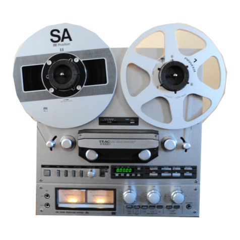
Harris CRITERION 90-1 User manual

www.SteamPoweredRadio.Com
LIST
OF
EFFECTIVE PAGES •
TOTAL
NUMBER
OF
PAGES
IS
AS
FOLLOWS
:
87
PAGE
NO
ISSUE
PAGE
NO
ISSUE
Title
Page .............
Origina
l
List
of
Effective
Pages
.
................
Original
iii
through
vii
.....
.
..
Original
1-0
through
1-4
........
Original
2-1
through
2- 6
..
......
Original
3
-1
through
3-7
........
Original
3- 8
........
.
..........
..
Blank
4-1
through
4-3
........
Original
4-4
....................
Blank
5-1
through
5- 25
.......
Original
5-26
.......
............
Blank
6-1
through
6-31
.......
Original
6-32
............
..
..
..
.
Blank
7-1
thr
ough
7-5
........
Original
7-6
....................
Blank
•
•
ii
WARNING: Disconnect primary power
prio
r
to
servicing.

www.SteamPoweredRadio.Com
•
•
•
SAFETY
NOTICE
WARNING:
THE
CURRENTS
AND
VOLTAGES
IN
THIS
EQUIPMENT
ARE
DANGEROUS
AND
UNDER
CERTAIN
CONDITIONS,
COULD
BE
FATAL.
This
manual
is
intended
as
general
guidance
for
trained
and
qualified
in-
stallation,
operating,
maintenance
and
service
personnel
who
are
fami
liar
with
and
aware
of
the
dangers
inherent
to
handling
potentially
hazardous
elec
tri
cal
and/or
electronic
circuits.
It
is
not
intended
to
co
ntain
a
complete
statement
of
all
safety
precautions
which
should
be
observed
by
personnel
in
using
this
or
other
electronic
equipment.
THE
INSTALLATION,
OPERATION,
MAINTENANCE
AND
SERVICING
OF
THIS
EQUIPMENT
INVOLVES
RISKS
TO
BOTH
PERSONNEL
AND
EQUIPMENT
,
AND
MUST
BE
PERFORMED
ONLY
BY
PROPERLY
TRAINED
AND
EXPERIENCED
PERSONNEL
EXERCISING
DUE
CARE.
PER-
SONNEL
MUST
FAMILIARIZE
THEMSELVES
WITH
SAFETY
REQUIREMENTS
,
SAFE
HANDLING
AND
OPERATING
PRACTICE,
AND
RELATED
FIRST-AID
PROCEDURES
(E.G. ,
FOR
ELEC
-
TRICAL
BURNS
AND
ELECTRICAL
SHOCK).
HARRIS
CORPORATION
Broadcast
Equipment
Division
shall
not
be
responsible
for
injury
or
damage
resulting
from
improper
installa
t
ion,
operat
i
on
,
main-
tenance
or
servicing,
or
from
the
use
of
improperly
trained
or
inexperienc-
ed
personnel
in
the
performance
of
such
tasks
,
or
from
the
failure
of
per-
sons
engaged
in
such
tasks
to
exercise
due
care.
As
with
all
electronic
equipment,
care
should
pe
taken
to
av
oid
elect
ri
ca
l
shock
in
all
circuits
where
substantial
currents
or
voltages
may
be
pr
e-
sent,
either
through
design
or
short
circuit.
Caution
should
also
be
ob-
served
in
lif
tin
g and
hoisting
equipment,
especially
regarding
large
struc
-
tures,
during
installation
.
LIABILITY
LIMITATION
The
procedures
outlined
in
this
Manual
are
based
on
the
information
avai
l-
able
at
the
time
nf
publication
and
should
permit
the
specified
use
with
minimum
risk.
However,
the
manufacturer
cannot
assume
liability
with
re-
spect
to
technical
application
of
the
contents
and
shall,
under
no
circum
-
stances,
be
responsible
for
damage
or
injury
(whether
to
person
or
proper
-
ty)
resulting
from
its
use
.
The
manufacturer
is
specifically
not
liable
for
any damage
or
injury
aris-
ing
out
of
failure
to
follow
the
instruc
t
ions
in
this
Manual
or
failure
to
exercise
due
ca
re
and
caution
dur
ing
installation,
operation,
mainte-
nance
and
service
of
this
equipment.
CAuT
I
ONARY
NOT
I
CE
Always
disconnect
power
before
opening
covers,
doors,
en
clos
ures,
gates
.
panels
or
shie
l
ds.
Always
use
grounding
sticks
and sho
rt
o
ut
high
volt-
age
points
before
se
rvi
cing.
Never make
int
erna
l
adjustments,
perform
maintenance
or
service
when
alone
or
wh
en
tir
ed.
Never remove, sh
ort-circuit
or
tamper
with
interlock
switches
on
access
covers,
doors,
enclosures,
gates,
panels
or
shields
. Keep away from
live
circuits
, know
yo
ur
equipment
and
don't
take
ch
ances.
Proper
training
of
experienced
personnel
and
observing
the
above
guide
lines
will
help
as-
sure
safe
and
con
tinu
ed
ope
ration
of
this
equipment.
iii

www.SteamPoweredRadio.Com
TABLE
OF
CONTENTS
Paragraph
SECTION
I.
DESCRIPTION
AND
SPECIFICATIONS
1-1.
Scope
..............•..........•.•.............•.....•...•......
1-1
1-6.
Equipment
Characteristics
•.
•
..•.•
.•....
•.•...•••.....•.
••
....
•.
1-2
2-1.
2-3.
2-5.
2-8.
2-
10
.
2-11.
2-13.
2-15.
2-17.
2-19.
2-21.
2-
23.
3-1.
3- 3.
3-5.
3-7.
4-1.
4
-5
.
4-
9.
4
-11.
4-13
.
4-17.
5-1.
5-
2.
5-4.
5
-6.
5-8.
5-9.
5-12.
5
-1
3.
5-14
.
5
-15
.
5
-1
7.
5-19.
5-21.
iv
SECTION
II.
INSTALLATION
Scope
Incoming
Inspection
and
Unpacking
...•..•.•..•.•
•..•.••
..
...•
..•
Unpacking
.
.....
.
~
•..
..
.......•.....................
.
...........
Returns
and
Exchanges
..
...
.........
.
...
.
......................
.
Installation
Procedures
........
.
..
.
....
............•...........
General
Requirements
. .
.....
. .
.........••..
•
......•
•...•..•...
Monophonic
Play
back
...•.......••.•...........................
Stereophonic
Playback
...................................•..
. .
Program
Output
Impedance
.•..•.....•.•....••...
.
.•.
••.
••....•
.
Record
Amplifier
Program
Input
..
............................
.
Record
Amplifier
Input
Impedance
......
•.
.....................
Remote
Control
Connections
.....
..
....
.
..
.
......
•....
.........
SECTION
III.
OPERATION
2-1
2-1
2-1
2-1
2-2
2-2
2-2
2-2
2-2
2- 5
2- 5
2-5
General
. . . . • . . . . . . . • . . . . . • . . . . • . • . . . . . . . . . . . • . . . . . • . . . . . . . . . . . .
3-1
Controls
and
Indicators
.......
.
........•.............•.........
3-1
Playback
Operating
Procedure
.••
.•
•.•
.....•.
•..•..••.•..•..•....
3-6
Record
Operating
Procedure
..•...•
•.•.
.
••.•.
. •
..•.
•.
. •
..
...••.•.
3-6
SECTION
IV
.
THEORY
OF
OPERATION
Playback
Program
Amplifier
(Monophonic
or
Left
Stereo
Channel)
.
4-1
Cue
Sensor
Ca
rd
. . . . . . . . . . . . . . . . . . . . . . . . . . . . . . . . . . . . . . . . . . . . . . . .
4-1
Record
Program
Amplifier
.....
.
•..•...
.
.......
..
. . . .
.......••.
. .
4-2
Bias
Oscillator
. . . . . . . . . . . . . . . . . . . . . . . . . . . . . . . . . . . . . . . . . . . . . . . .
4-2
Three-Tone
Oscillator
. .
.....
........•..•..•.......•............
4-2
Control
Functions
.............•...........
..
.
...
...
. .
...
....
...
4-3
SECTION V.
ADJUSTMENTS
AND
MAINTENANCE
Preventive
Maintenance
Record/Playback
Heads
..............
.
........
.
.........
.
.....
.
Capstan
and
Pinch
Roller
..
....
. .
....
....
. .
....
.
....
.
..
..
. .
..
.
Pinch
Roller
Cross
Shaft
•..............................
.
.....
Head
Replacement
and
Adjustme
nt
.....
.
..............•..•..•.....
Replacement
..........
.
.....
..
......
....
..•...........•..•..•.
Height
Adjustment
. ,
.......•..•...•...........•.•..•..••....
Azimuth
Adjustment
. .
....
....•.....•..............•....•..••
Stereo
Phase
Playback
Adjustment
. .
........................
.
Deck
Adjustments
..
..•
...........•.......
••
.
••••.
...
.•
.
.•
.•
•.••
.
Cross
Shaft
Assembly
........................................
.
Motor
Position
•............
.....
..
.
.....
...............
......
Solenoid
Adjustment
. .
......................................••
WARNING: Disconnect
primary
power
prior
to
servicing
.
5
-1
5-1
5-1
5-1
5-1
5-1
5-3
5-5
5-5
5-7
5-7
5-7
5-7
•
•
....
"
N
1.0
•

www.SteamPoweredRadio.Com
• Pa
ragrapr
5-25.
5-26.
5-28
.
5-29.
5-31.
5-33.
5-34.
TA
ELE
ot
CON
T
ENTS
(Con
t
inued)
~a
ge
Electrical
Adjustments
....
...
..................
..
..............
5- 9
Adjustment
Locations
and
Fun
c
tions
....
.
...............
.
..
. .
..
5-9
Cue
Sensor
Adjustment
...................
.
..
......
.
...
...
...
5-9
Record/Program
Amplifier
Alignment
.............
..
........
.
...
5-
20
Playback
Program
Amplifier
Adjustments
.......................
5-20
Cue
Frequen
cy and Record
Level
Adjustments
.........
..
......
5-21
Operating
Voltages
.............•...
.
....
.
..
.
.....
.
...........
..
5-22
SECTION
VI .
PARTS
LIST
6-1.
Introduction
. .
....
.........
.................
•
........
.
........
•
6-1
6-3.
Replaceable
Parts
Servi
ce
...........•............•.............
6-1
6-5.
Technical
Assistance
.........
.
.......
..
.........
.
..
.
...........
6-1
SE
CTIO
N
VlI.
DIAGRAMS
7-1.
Introduction
7-1
•
• V
WARNING· Disconnect primary power
prior
to servi
r.
ing.

www.SteamPoweredRadio.Com
LIST
OF
TABLES
Table
1-1.
Criterion
Cartridge
Tape
Units
....•........•..•......
.
..........
1-2.
Criterion
90
Characteristics
.................................
. . .
2-1.
Playback
External
Connections
..................................
.
2-2.
Record
External
Connections
....................................
.
3-1.
Playback
Controls
and
Indicators
...............................
.
3-2.
Record
Controls
and
Indicators
.......
...
..................
..
...
.
5-1.
Stereo
Program
Amplifier
Adjustments
(Figure
5-8)
..............
.
5-2
.
Cue
Sensor
Adjustments
(Figure
5-9)
....
.
...................
....
.
5-3.
Record Program
Amplifier
Adjustments
(Figure
5-10)
..
..
..
. .
.....
.
5-4.
Bias
Oscillator
Ad
j
ustments
(Figure
5-11)
......................
.
5-5.
Three-Tone
Oscillator
Adjustments
(Figure
5-12)
...............
. .
6-1
.
Replaceable
Parts
List
Index
.
..
....
•...
...
.
...........
.
.....
.
...
6-2
.
Criterion
90-1
and
90-2
Playback
Chassis
..
.
....................
.
6-3.
Mono
Program
Amplifier
. .
.........
.
..
.
..
.
.....
.
..
.
..............
.
6-4.
Stereo
Program
Amplifier
.......................................
.
6-
5.
Cue
Sensor
Boa
rd
........
. . . . .
.............
.
......
.
.............
.
6-6.
Record/Program
Amplifier
....................•...................
6-7.
Bias
Oscillator
Module
..............•...........................
6-8.
Tone
Oscillator
Module
...........................
.
.....
..
.....
. .
6-9
.
Auxiliary
Equipment
..............................
..
...........
. .
vi
WARNING: Disconnect primary power prior
to
servicing.
1-1
1-3
2- 5
2
-6
3-3
3-5
5-11
5-13
5-15
5-17
5-19
6-2
6- 3
6-10
6-12
6-16
6-22
6-25
6-27
6-31
•
•
I-'
-..J
N
'°
•

www.SteamPoweredRadio.Com
•
•
•
LIST
OF
ILLUSTRATIONS
1-1.
Criterion
90-1
and
90-2
Record/Playback
Units
....
...
.........•
.
1-0
2-1.
Criterion
90
Rear
Panel
Connections
...........
. .
..
.
•.........
. .
2-3
2-2.
Input/Output
Transformer
Connections
.•...........
.
.....
.
.......
2-4
3-1.
Playback
Controls
and
Indicators
(Common
to
all
Units)
.........
3-2
3-2.
Record
Controls
and
Indicators
........
.
.....
.
......
..
.
...
..
...
.
3-4
5-1.
5-2.
5-3
.
5-
4.
5
-5.
5-6.
5-7.
5-8.
5-9.
5-10.
5-11.
5-12
.
7-1.
7-2
.
Head
Wiring
(Rear
View)
..
.
........
.
......
...
.
....
..
.
...........
5-2
C
riterion
90-1
and
90-
2,
Tape Deck
Dimensions
...
.....
...
.......
5- 2
Head/Guide
Height
Gauge
.....
.
....
.
......•.....•................
5-4
Head
Adjustments
.....................................
.
......•..
5-4
Head Assembly, Tape
Guide
...
....
..
....
. .
.............
. •
......
. .
5-4
Stereo
Phasing
Patterns
.
.......
...........•.....•
..
....
...
.....
5-6
Pinch
Roller
Adjustment
Gauge
(Larger
Portion
of
Gauge
815 0842 001)
...
...
.•...
.
...
.
......
.
............•..............
5-8
Stereo
Program
Amplifier,
Adj
u
stment
Locations
....
..
.
•.
.
.......
5-10
Cue
Sensor,
Adj
us
tment
Locations
. . . . • .
..
..
• . . . . .
..
..
..
. . . .
..
..
.
5-12
Record
Program
Amplifier,
Adjustment
Locations
..
.
.............•
5-14
Bias
Oscillator
,
Adjustment
Locations
. .
....
........
.
..
.........
5-16
Three-Tone
Oscillator,
Adjustment
Locations
......•.......
.
.....
5-18
Criterion
90-1
and
90-2
Playback
. •
..
•....
....
..........••
. . •
...
7-3
Criterion
90-2
Record . .
.•......
.....
..........•..•
..
•..
.
....
...
7-5
vii
WARNING
:
Disconnect
primary
power
prior
to
servicing
.

www.SteamPoweredRadio.Com
•
•
°'
N
,-..
.-I
•
1-1.
SCOPE
.
SECTION
I
DESCRIPTION
AND
SPECIFICATIONS
1- 2.
This
manual
provides
operating
and
maintenance
info
r
mation
for
the
Criterion
90-1
playback
unit,
the
Criterion
90-2
record/playback
unit,
and
the
Criterion
90-2
playback
only
unit
(figure
1-
1).
Each
of
the
units
is
available
in
either
monophonic
or
stereophonic
configuration.
In
addi-
tion,
the
units
can
also
be
specified
by
the
customer
for
117-volt,
50-Hz
operation.
The
manufacturer's
part
number and
NAB
cartridge
sizes
for
each
configuration
are
listed
in
table
1-1.
Table
1-1.
Criterion
Cartridge
Tape
Units
UNIT
PART
NO.
NAB
CARTRIDGE
SIZE
Criterion
90-1-Mono 994 7993 001 A
or
B
Playback
Crite
ri
on
90-1-Ste
reo 994 7994 001 A
or
B
Playback
Criterion
90-2
-M
ono 994 7995 001 A, B,
or
C
Playback
Criterion
90-2-Stereo
994 7996 001
A,
B,
or
C
Playback
Criterion
90-2-Mono 994 7997 001
A,
B,
or
C
Record/Playback
Criterion
90-2-Stereo
994 7998 001
A,
B,
or
C
Record/Playback
1-3.
The
tape
units
use
solid-state
electronics,
consisting
of
sili
-
con
transistors
and
integrated
circuits,
to
provide
temperature
and
gain
stability.
1-4.
The
heart
of
the
Criterion
90
machines
is
the
synchronous
hysteresis
motor
with
direct
capstan
drive.
The
motor
assembly
is
precisely
mounted on a
heavy
half-inch
aluminum
deck
plate,
and
uses
a full-'SW'ing
pressure
roller
to
provide
optimum
tape
accuracy
.
1-1
WARNING: Disconnect primary
power
prior
to
servicing.

www.SteamPoweredRadio.Com
1-5.
The
high
quality
laminated
heads
employ
an
all-metal
hyperbolic
face
to
provide
long
wear
and
low
oxide
accumulation.
Three
tape
guides,
together
with
the
playback
and
rec
o
rd
heads
assures
the
optimum
in
tape
path
guidance.
The
playback
only
model
has
a
dummy
head
installed
in
the
left
head
slot
.
1-
6.
EQUIPMENT
CHARACTERISTICS.
1-7,
T
able
1- 2
lists
the
electrical
and
physical
cha
racteristi
cs
of
the
Criterion
90
playback
and
record
unit,
1-2
WARNING: Dfsconnect primary
power
prior
to
servicing.
•
•
~
-..J
N
v:,
•

www.SteamPoweredRadio.Com
•
•
a,
N
,.....
..-I
•
Table
1-2.
Criterion
90
Characteristics
FUNCT
I
ON
Frequency
Response
Noise
(Measured
without
muting)
Muted
Noise
Equalization
Output
Cue
Signals
Tape Speed
Tape
Drive
System
Tape Speed
Accuracy
Wow
and
Flutter
Heads
Remote
Control
Power
Source
Power
Requirement
Ambient
Temperature
CHARACTERISTIC
+2 dB
at
300
to
15,000
Hz; +3
-2
dB
at
50
Hz
to
300 Hz.
55
dB
,
or
better
,
below
the
reference
level
of
160
nWb/m
at
1 kHz.
Better
than
-75
dBm.
Complies
with
NAB
Recording
and
Repro-
ducing
Standards;
CCIR
equalization
available
on
special
order
.
+18
dBm
clipping
point,
normally
O
dBm
with
standard
NAB
level
recording.
600-ohm
balanced
impedance
with
150-ohm
operation
.
1000-Hz
Primary,
150-Hz
Secondary,
and
8000-Hz
Tertiary.
The
tertiary
relay
is
available
as
optional
equipment.
7-1/2
inches
per
second;
3-
3/4
or
15
inch
on
special
order.
Direct
capstan
drive
employing
sealed
ball
bearings
. Tape
start
and
stop
time
is
adjustable
with
a 0.08
second
minimum.
0.1%,
or
better.
0.15%
NAB
unweighted,
or
less.
NAB
standard.
All
control
functions
via
ground
switching.
117 Vac +10%, 60 Hz;
50
Hz
on
special
order.
70
watts
, maximum.
0
55
C,
maximum
.
1-3
WARNING: Disconnect primary power p
rior
to
servicing.

www.SteamPoweredRadio.Com
Table
1-2.
Criterion
90
Cha
racteristi
cs
(Continued)
FUNCTION
Dimensions:
Rackmount
Desktop
Cabinet
Weight
External
24
Volt
DC
Load
Current
1-4
Height:
Width:
Depth:
Height:
Width:
Depth:
CHARACTERISTIC
7
inches
(17.78
cm)
19
inches
(48
.26
cm)
15
inches
(38.1
cm)
5-1/2
inches
(13.97
cm)
Criterion
90-1:
8-5/8
inches
(21.
91
cm)
Criterion
90-2:
17-1/8
inches
(43.
82
cm)
Criterion
90-2
Playback
Only
Model: 10-
1/4
inches
(26.
04
cm)
15
inches
(38.2
cm)
Criterion
90-1:
23
lbs.
(10.4
kg)
Criterion
90-2
Record/Playback:
34
lbs
. (15 .4
kg)
Criterion
90-2
Playback:
25
lbs
.
(11.
3
kg)
200
mA
WARNING: Disconnect primary power
prior
to
servicing.
•
•
....
'-I
N
\0
•

www.SteamPoweredRadio.Com
•
•
•
2-1.
SCOPE,
SECTION
II
INSTALLATION
2- 2.
This
section
contains
information
on
the
inspection,
unpacking,
and
installation
of
the
Criterion
90
-1
and
90-2
Record/Playback
units.
In-
structions
for
system
interconnection
are
provided
and
include
illustrations
showing
the
cabling
connections
for
the
various
equipment
items.
External
connections
are
tabulated.
During
installation
of
the
equipment,
standard
safety
practices
are
to
be
used,
and
strict
adherance
to
the
cautionary
notes
specified
in
the
text
is
stressed.
2-3
.
INCOMING
INSPECTION
AND
UNPACKING.
2-4.
Domestic
shipment
of
the
equipment
is
normally
conducted
via
pri-
vate
carrier.
Care
should
be
exercised
in
unloading
the
equipment
to
prevent
injury
t o
pe
r
sonnel
and
damage
to
the
equipment
. Upon
delivery,
the
shipping
container
should
be
examined
for
indications
of
possible
mishandling.
If
damage
is
evident,
immediately
notify
the
carrier
and
Harris
Corporati
o
n,
Broadcast
Products
Division
(refer
to
paragraph
2-8,
Returns
and
Exchanges)
.
2-5
.
UNPACKING
.
2-
6.
Proper
handtools
are
to
be
used
in
unpacking
the
equipment.
To
prevent
damage
to
the
equipment
finish,
do
not
use
a
knife
or
other
sharp
utensil
to
remove
the
protective
material.
The
containers
are
to
be
opened
from
the
top,
and
the
equipment
carefully
removed.
The
control
tags
attach-
ed
to
the
equipment
are
to
be
checked
against
the
Packing
Check
List
to
veri-
fy
that
the
shipment
is
complete.
Any
discrepancy
is
to
be
reported
imme-
diately
to
Harris
Corporation,
Broadcast
Products
Division
(refer
t o
para-
graph
2-
8).
2-7.
During
removal
of
the
system
components
from
the
containers,
in-
spect
them
for
obvious
defects,
missing
parts,
and
loose
or
incorre
ct
hard-
ware.
Operate
the
front
panel
controls
and
switches
to
ensure
freedom
of
movement.
Loosen
the
wing
nut(s)
at
the
rear
of
the
unit,
and
remove
the
top
access
cover
. Remove
the
fibreboard
shipping
holddown
and
as
c
ertain
that
all
printed
circuit
modules
are
installed
and
properly
seated.
2-8.
RETURNS
AND
EXCHANGES.
2-
9.
Equipment,
damaged
or
undamaged,
should
not
be
returned
until
written
approval
and
a
Return
Authorization
is
received
from
Harris
Corpora-
tion
,
Broadcast
Products
Division
.
Special
shipping
instructions
and
c
oding
will
be
provided
to
assure
proper
handling
and
prompt
issuance
of
credit.
Complete
details
regarding
the
circumstances
and
reasons
for
return
are
to
be
included
in
the
request
to
return
.
Customized
equipment
and
special
order
equipment
is
not
returnable.
In
those
instances
where
return
or
exchange
of
equipment
is
at
the
request
of
the
customer,
or
the
convenience
of
the
2-1
WA
RN
ING: Disconnect primary power pr
ior
to
servicing.

www.SteamPoweredRadio.Com
customer,
a
restocking
fee
will
be
charged.
All
returns
will
be
sent
freight
prepaid
and
properly
insured
by
the
customer
.
When
communicating
with
Harris
Corporation,
Broadcast
Products
Division,
specify
the
Factory
Order
Number
or
Invoice
Number.
2-10
.
2-
11.
INSTALLATION
PROCEDURES
.
GENERAL
REQUIREMENTS.
2-12.
The
location
of
the
Criterion
90 un
it
(s)
in
an
individual
station
will
be
determined
by
the
arrangement
of
the
main
control
room
facilities.
The
placement
of
equipment
and
wiring
should
be
carefully
planned
before
in
-
stallation
work
is
started.
Care
should
be
taken
to
provide
for
adequate
ventilation
.
2-
13.
WARNING I
The
protective
covers
on
the
under
side
of
the
chassis
are
for
your
protection
.
Do
not
operate
equipment
with
covers
re-
moved .
MONOPHONIC
PLAYBACK.
2-14.
Connect
a
two-conductor
shielded
cable
between
the
desired
audio
console
input
terminals
and
the
600-
ohm
program
output
terminals
3 and 5
of
playback
connector
J2
(figure
2-1).
The
shield
of
the
cable
should
be
con-
nec
t
ed
to
terminal
1.
2-
1
5.
STEREOPHONIC
PLAYBACK.
2-16.
Connections
for
the
stereo
left
channel
are
simila
r
to
the
mono
-
phonic
audio
channel.
The
stereo
r
ight
channel
is
connected
to
terminals
4
and
6
of
J2
with
pin
2
connected
to
the
shield
.
Phasing
should
be
caref
ul
ly
observed
.
Terminals
1,
3,
and
5
for
the
left
channel
are
identical
to
the
r
ight
channel
terminals.
Refer
to
table
2-1.
2-
17.
PROGRAM
OUTPUT
IMPEDANCE
.
2-
18. The
output
transformers,
T2
and
T3,
are
normally
impedance
matched
to
a 600-ohm
line
(figure
2-2).
Impedance
may
be
changed
to
150
ohms
by
removing
the
jumper
between
terminals
4A
and
SA
(figure
2-2)
,
and
adding
a
jumper
between
terminals
3
and
4,
and
another
jumper
between
te
r
mi-
nals
5
and
6
at
the
bottom
of
the
Record
motherboard.
The
right
program
transformer
T3,
w
hen
used
,
can
be
changed
by
following
these
same
direction
s .
2-2
WARNING: Disconnect
pr
imary power
prio
r
to
servicing.
•
•
•

www.SteamPoweredRadio.Com
•
•
•
2-19.
TERMINAL
Jl-1
Jl-2-3
Jl-4-5
Jl-6
Jl-7-1
Jl-8-1
Jl-9
-11
Jl-10-11
Jl-14
Jl
-
15
Jl
-
16
Jl-17
J2-1
J2-3-5
J2-2
J2-4-6
Table
2-1
.
Playback
External
Connections
FUNCTION
Ground
Tertiary
Cue
Switching
Secondary
Cue
Switching
Primary
Cue
Stop
Remote
STOP
Remote
START
Remote
READY
Indication
Remote
START
Indication
Bias
Control
Positive
24
Volts
Cue Pre-Amp. Output
(Logging)
Logging
IN
Shield
Ground
Monophonic,
or
Left
Stereo
Program
Output
Shield
Ground
Right
Stereo
Audio
Output
(if
used)
RECORD
AMPLIFIER
PROGRAM
INPUT .
2-20
.
Connect
a
two-conductor
shielded
cable
between
the
desired
audio
input
(monophonic or
left
stereo
c
hannel)
to
terminals
3 and S
of
J4
with
the
shield
connected
to
terminal
1.
For
stereo
operation
connect
the
right
channel
audio
to
terminals
4
and
6
of
J4,
and
the
shield
to
terminal
1. The
connec
ti
ons
are
listed
in
table
2-2
.
2-21.
RECORD
AMPLIFIER
INPUT
IMPEDANCE.
2-22.
The
input
transformers
are
normally
connected
to
match
a
balanced
600-ohm
line
(figure
2-2)
.
Impedance
is
changed
to
150
ohms
by
reconnectin
g
jumper(s)
on
the
input
to
the
transformer.
Change
to
jumpers
immediately
next
to
resistors
R24
and
R26
so
that
the
end
of
th
e
jumper
nearest
to
the
particular
transformer
is
connected
to
the
vacant
center
terminal
of
the
transf
o
rmer.
To
change
to
20k
ohm
bridging
input
, rem
ove
both
jumpers
for
each
transformer
or
four
in
all
(refer
to
figure
2-2).
2-23
.
REMOTE
CONTROL
CONNECTIONS.
2-24.
All
control
functions
may
be
remotely
controlled.
Refer
to
tables
2- 1 and
2-2
for
the
proper
connections
•
2- 5
WARNING: Disconnect primary power
prior
to
servicing.

www.SteamPoweredRadio.Com
2- 6
TERMINAL
J3-l
J3
- 2
JJ-3
J3-4-6
J3-5
JJ-6-7
J3-8
J3-9-10
J3-ll
J3-12
J4-l-2
J4
- 3- 5
J4-4-6
Table
2-
2.
Record
External
Connections
FUNCTION
1-kHz Cue
Inhibit
1-kHz Cue
Add
Ground
Remote 150-Hz Cue Keying
Not Used
Remote 8-kHz
Cue
Keying
Not Used
Remote Record
SET
Not Used
Remote
SET
Indication
Shield
Ground
Monophonic,
or
Left
Stereo
Audio
Input
Right
Stereo
Audio
Input
WARN
ING:
Disconnect primary power
prior
to
servicing.
•
•
~
-..J
N
\0
•

www.SteamPoweredRadio.Com
•
•
•
3-1.
GENERAL.
SECTION
III
OPERATION
3-2.
This
section
provides
information
regarding
the
identifica
ti
on
,
location,
and
function
of
the
controls
and
indica
t or s
on
the
Criterion
90
playback
and
record
units.
The
section
also
contains
information
on
play-
back
and
r
ec
ord
operating
pro
c
edures.
3-3.
CONTROLS
AND
INDICATORS
.
3- 4 .
The
con
t
rols
for
Criterion
90
playback
units
are
shown
in
fig
ur
e
3-1
and
their
functions
are
described
in
t
able
3-1
.
The
r
ecord
controls
are
illustrated
in
figure
3- 2
and
their
functio
ns
are
described
in
table
3-2
.
3-1
WARNING: Di
sco
nnect primary
power
prior
to
servicing.
This manual suits for next models
1
Table of contents


