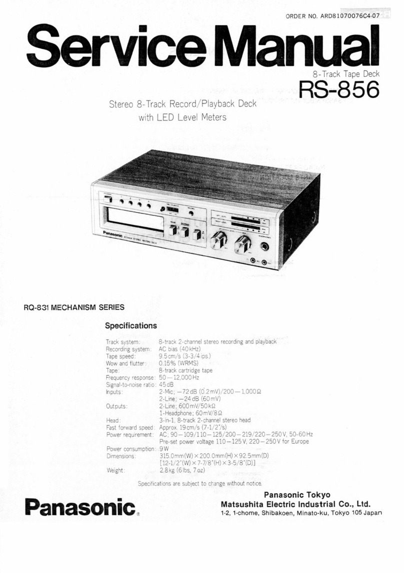
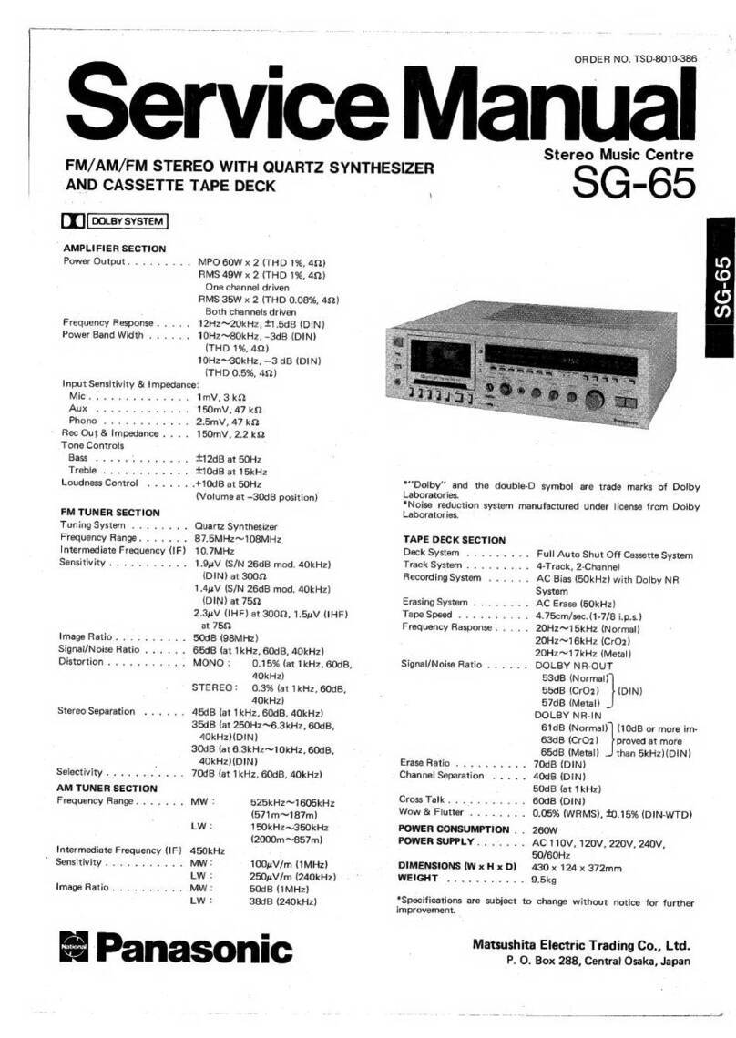
Panasonic RS-715US User manual

Service
Manual
TAPE
RECORDER
PANASONIC
|
|
4-TRACK
STEREO
TAPE
DECK
WITH
3-MOTORS,
4-HEAD
AND
AUTOMATIC
REVERSE
SPECIFICATIONS
Power
Source:
Power
Consumption:
Motors:
Transistors:
Diodes:
Rectifiers:
Track
System:
Recording
System:
Erasing
System:
Tape
Speeds:
Maximum
Reel
Size:
Signal-to-noise
Ratio:
100~240
volts
110
W
8/4
poles
dual
speed
hysteresis
synchronous
motor
(1)
4-pole
induction
motor
(2)
2S8C644®(8)
2SC828(8)
250881
(2)
2SD261(2)
2SC1096(1)
2SC644
(6)
OA90(4)
1S8150(1)
FR2(8)
KC2dp22/1(1)
4
tracks,
2
channels
stereo
recording
and
playback
AC
bias
180
kHz
AC
erase
2
speeds,
7-1/2
ips
(19
cm/s)
and
3-3/4
ips
(9.5
cm/s)
50/60
Hz
7”
reel
53
dB
or
more
Fast
Forward
Time:
Rewind
Time:
Frequency
R
Wow
&
Flutter:
Inputs:
Outputs:
Record/Playback
Connector:
Dimensions:
Weight:
RS-715US
Less
than
60
seconds
for
7”
standard
tape
(1200
ft)
Less
than
60
seconds
for
7”
standard
tape
(1200
ft)
20~25,000
Hz
(30~22,000
Hz
'
+3
dB)
at
7-1/2
ips
Less
than
0.095%
at
7-1/2
ips
2
“MIC”
(High)
—65
dB
(0.56
mV)/5
~20
KQ
(Low)
—73
dB
(0.22
mV)/
6002~5
KQ
2
“LINE
IN”
—30
dB
(30
mV)
/200
KQ
2
“LINE
OUT"
—6
dB
(500
mV
)/50
KQ
“HEADPHONE”
8
DIN
17” (W)
x
20-3/4”
(H)
x
9”
(D)
52-7/8
Ibs.
These
specifications
are
subject
to
change
in
order
to
accommodate
improvements
in
design.
ORDER
NO.
ARD-7110132
MATSUSHITA
ELECTRIC
fos
MATSUSHITA
ELECTRIC
TRADING
CO.,
LBD.
righed
P.
O.
Box
288
Central,Osaka,
Japan

LOCATION
OF
PARTS
@
Supply
reel
table
@
Head
assembly
housing
@®
Takeup
reel
table
@
Right
tension
arm
®
Capstan
Pressure
roller
@
Operation
buttons
Tape/source
selection
knobs
@®
Power
source
switch
Tape
selector
knob
a
Record
selector
buttons
@
Output
level
control
knobs
4
Line
input
level
contro!
knobs
Microphone
input
level
control
knobs
@®
Record
button
Microphone
jacks
@
Headphones
jack
Level
meter
zero-point
adjustment
screws
Level
meters
@)
Tape
speed
selector
@)
Automatic
reverse
selector
@
Tape
tension
selection
button
@
Gide
pin
@
Tape
counter
and
reset
button
@)
Left
tension
arm
@)
Power
frequency
selector
@
Power
voltage
selection
switch
@
Remote
contro!
jack
@)
MIC
impedance
selector
switch
60
Line
in
jacks
6)
Recording/playback
connector
$2
Sound-on-sound
level
adjustment
control
@}
Sound-on-sound
switch
64
Line
out
jack
@)
Fuse
holder
(for
2A
fuse)
6
Power
outlet
@)
Sensing
poles
@)
Tape
guids
69
Playback
head
@)
Tape
shifter
Record
head
@
Erase
head
@
Front
cover
3635)
°34}33'32)
31)
30:29)

DISASSEMBLY
INSTRUCTIONS
HOW
TO
REMOVE
BACK
BOARD
(B)
Fig.
2
1.
Remove
4
screws
in
the
rubber
feet
(A)
and
2
back
|
2.
Then
back
board
can
be
removed.
board
holding
screws
(B).
HOW
TO
REMOVE
BODY
CASE
iC)
\
Fig.
3
be
1.
Remove
10
body
case
holding
screws
(C).
2.
Place
the
set
with
its
panel
side
up
and
lift
body
case
(panel
side)
slowly.
Then
body
case
can
be
removed.

STANDARD
VALUE
TO
BE
ADJUSTED
RTS
(TEM
VALUE
aa
ee
Be
REMARKS
+0.6
ates
Leg.
ma
cahen
VR17
(CH1)
-
Recording
bias
current.
19.cm/s
of
tape
VR18
(CH2)
Set
$3
to
normal
position.
speed).
MIC
—73+3dB
To
obtain
160zA
of
recording
signal
Input
level.
LINE
-—30+2dB
—
i
current.
DIN
—38+42
dB
Set
S1
to
low
position.
Bias
oscillation
frequency.
180+10
kHz
ene
eee
ee
Erase
current.
38~50
mA
—_——
—_—__—
Terminal
A
of
VR23
(Forward)
Change
the
position
of
terminal
A
of
PaNCUP
Seven:
pe
ect
Terminal
A
of
VR22
or
VR23.
VR22
(Reverse)
ep
ere
‘Lerma
er
Set
$23
to
THIN
position.
Back
tensi
conker)
VR22
(Left)
|
Change
the
position
of
terminal
B
of
ek
Rerielal.
29~33
gr-cm
Terminal
B
of
vara
vpos
:
.
(for
Right)
VR23
(Right)
.
Setting
position
of
Loosen
4
nuts
and
change
the
setting
pressure
arm
rod
position.
:
Pressure
of
pressure
roller.
eS
eU
ike
(M104)
on
plunger
After
compiete
adjustment,
lock
the
4
rod
(M108).
nuts
tightly.
Brake
spring
(shown
By
change
of
hunging
position
(hole)
Brake
tension.
120+29
gr
by
No.
M50
in
on
brake
arms
(shown
by
No.
M49
and
exploded
views).
M51
in
exploded
views).

ELECTRICAL
PARTS
LOCATION

CABINET
PARTS
G25
G24
G30
G25

SCHEMATIC
DIAGRAM
MODEL
RS-715US
Trl
Tr3
Tr5
Tr7
2sc644®
1oSI
1
¥R3,
20KIA)
2Sc644©
2SC644
2SC828
w3e
2scesr
x2
pense
7
|
:
!
mic
||
|
|
|
Cc
|
°?
!
LEFT
|
;
I
LINE
IN
@
l
cae
|
!
H
TO
CONTROL
LINE
IN
@
C204A
rae
205),
VRLI
20K
(A)
Sue
VRA
208m
source
1d
$4-1
READS
Te
hae
ee
Tra
Te8
a4
r
———_-28c644®
TEE
&
db
280644
SC644
R127
33K
|
{
|
+
ge
035
PLAY
HEAD
|
ws
ROS
F—>
©
|
€37_
470P
O O
i}
©
%
a
a
PLAY
BACK
O
||
Pag
SOK
|
H
|
3
C45
@
RY
7
HEAD
|
|
R65
330
eft
@
R
rid
es
Les
2SC828
X2
PHONE
|
|
THO
asce44@x2
043
0027
Trig
28C644
X2
mK
2evi00
PLAY
HEAD
|
!
ase
636
ua
O
y
C48
4
FG
y|
1ev10
,
q
[RIGHT]
|
a
5
|
?
iis
(Vv
:
r—<§
?
aan
OR
ISS
”
dt
4
HO
73)
R84
180K
(ay
were
0
rrc50
ee
58
mes
|
Beca
Sap
A
gf
eee
.
ei
ae
R62
“Movie
)2.2k.
R76:
eset
|
S88
coo
:
120K
wag
Smt
Tex
es
i
er
eae
Te2
R66
330
C42
16VI0
R134
R136
gs
R130
39K
0.00
100K
20K
2
y
Scenes
ek
aOR
RL
c44
0027)
irre
et
a
Re
ee
te Pe
ae
1s
Ler}
;
¥,
SOURCE
2
snis
vondal
SOURCE
2
Tr26
2SD
261

QO
oO
i
REC
REVERSE
F.REW
STIOP
FORWERD
PAUSE
j
TO
AMP
k
$246
$25
$30
POWER
LAMP
S16
(ay
Sak
527
$31
oy
oy
oh]
oh
oy
@) oO
oO
0 0 O
Oo
'e)
0
O
Q
©
S
TO
AMP
TroSlucinias
MIC
impeadance
select
switch
(shown
in
Low
position).
BS
2
ecto
tec
scst
Equalizer
select
switch
(coupled
with
$12).
Liked
Hight,
2......
Low.
3.S3.c4a-gan
Tape
select
switch.
Low.
SG,
2......NORMAL.
4
SB
echt
cee
Left
monitor
select
switch
(shown
in
tape
position).
Tawi
SOURCE,
2......
TAPE.
BOSS
shai
deanis
Right
monitor
select
switch
(shown
in
tape
position).
vi
9
coe
ypu
1...
TAPE,
2......SOURCE,
62
SGeeaae
Head
select
switch
conpled
with
RY1
(shown
in
forward
LAA
rs
a)
A
position).
VR20
300
‘40w)
seers
FORWARD,
2......
REVERSE.
;
VR23
800
(40W)
y
macy
Sherer
cee
ee
Record,playback
select
switch
(shown
in
playback
1
Position).
82,300,400)
;
B.
SB.
ee
Sound
on
sound
select
switch
(show
in
OFF
position).
Pw
BIA
1......From
Right
to
Left,
2......OFF,
3......
From
Left
to
Right.
bw
I
..
Power
ON/OFF
switch.
$23-2
...
AC
voltage
select
switch.
-
50/60
Hz
select
switch
(shown
in
60
Hz
position).
Shut
off
switch.
...
Motor
switch
(coupled
with
RY2).
..
Auto
reverse
switch.
Record
switch.
Reverse
switch
(coupled
with
RY3).
..
Rewind
switch
(coupled
with
RY4).
Tape
speed
select
switch
(shown
in
9.5
cm/sec
position).
19.
20.
21.
22.
23.
24.
25.
26.
27.
28.
29.
30.
31.
32.
33.
34.
35.
36.
37.
38.
39.
40.
41.
42.
43.
44,
45.
46.
47.
48.
STANDARD
VOLTAGE
CHART
Voltage Voltage
120V
23.5V
3.1V
0.32V
11.5V
1L7V
11.5V
2.6V
|
6.2V
24.0
V
1.07V_
16.0V
5.5V
24.0V
1.16V
17.2V
5.2V
19.6V
3.0V
10.0
V
cS)
9.8V
25.4V
8
2.13V
26.6
V
®
3.02
V
0.2V
©
0.52V
19.5
21V
21.8V
®
24.5V
®
®
9.7V
NOTE:
All
measurements
are
under
no
signal
con-
ditions
with
volume
at
minimum
posistion.
Use
P-type
VTVM
for
voltage
measurements.
$19...
..
Fast
forward
switch
(coupled
with
RY5).
$20
Forward
switch
(coupled
with
RY6).
$21
Delay
switch
(coupled
with
RY7).
$22
Record
switch
(coupled
with
RY8).
$23...
..
Back
tension
select
switch
(shown
in
NORMAL).
1
a
NORMAL,
2......
THIN.
$24,
25
.
Reverse
switch.
$26
...
Fast
rewind
switch.
$27
Stop
switch.
$28
...
.-.
Fast
forward
switch.
$29,
30
......
Forward
switch.
$31...
Pause
switch.
VR1,
2
LINE
IN
level
control.
VR3,
4
MIC
level
adjustment.
VR5.
6
Record
level
adjustment.
VR7,8
Playback
equalizer
adjustment
at
7-1/2
ips.
VRQ,
10
Playback
equalizer
adjustment
at
3-3/4
ips.
VR11,12
...
Output
level
control.
VR13,
14
...
Level
meter
adjustment
at
Tape.
VR15,
16
...
Level
meter
adjustment
at
source.
VR17,18
...
Recording
bias
adjustment.
VR19_
..,.......
Sound-on-sound
level
adjustment.
VR20
Forward
back
tension
adjustment
for
THIN
position.
VR21
Reverse
back
tension
adjustment
for
THIN
position.
VR22A
Reverse
take
up
torque
adjustment
for
NORMAL
position.
VR22B
Forward
back
tension
adjustment
for
NORMAL
position.
VR23A
Forward
take
up
torque
adjustment
for
NORMAL
position.
VR23B.........
Reverse
back
tension
adjustment
for
NORMAL
position.
Resistor
are
ohms
(Q.:),
1/4
watt
unless
specified
otherwise.
K=1,000Q,
M=1,000,000Q.
The
bracketed
numbers
followed
the
resistors
show
the
wattage
of
the
resistors.
Capacitors
are
microfarad
(uF)
unless
specified
otherwise.
P=Micro-microfarads.
Encircled
numbers
(©)
show
the
checkpoints
for
voltage.
The
values
are
marked
in
the
standard
voltage
chart.

CIRCUIT
BOARD
PLAYBACK
CIRCUIT
BOARD
3.02V
ax
]
[18.0
|
0.52V
$.7V
24.5V
|
3.1V
|
0.32V
J
J
|
TrlL9
28C644x
2
14
‘nah
rot
T1210
28c644x2
tT!
24.5v
|
[11.7
;
3
17.2V
[to.ov
|
i
a
!
KC2dP22/1
!
[23.5v
]
(Snr

RECORD/PLAYBACK
SELECT
CIRCUIT
BOARD
RECORD
CIRCUIT
BOARD
RIS
10k
1.07V
[5.2v
3.0v
|
t16v
|
.
6.2V
OPERATION
CIRCUIT
BOARD
i
es
moe
oats
STILE
|
oo
a,
ca
O
QO
QjI9O324
NOTE:
The
circuit
shown
in
red
on
the
conductor
side
is
+B
circuit.
Values
indicated
in
[_]
are
DC
voltages
between
the
chassis
and
electrical
parts.
«

EXPLODED
VIEWS
i
N
pis
iy
cl
TT
Ws
ea
=
ey
YY
spo
=
—:
:
Se
*
a
AA
rit
RAPS
Mee
regae
©
rennas
M38
M39
M40
M3
M31
M3
M35
M3
M4
|M32]M33
|
M4
|
M33
M3
-
M37
10

|
O
M42
M41-4M41-2
M22
M43
M53
M53B
M24
M49
M24
M27
M51
M9
41-1
M534;
M54
|
M39
M60
|
|
M41
|M41-3/M
M39
M27
|
M50
I
|
Clase
M42
|M46|
M47
|M58{
M60
|
M27
|
M55
|
M64
mes
|
M67
M65
|
M3
M44
M46
M45
M48
M60 M59 M56
M57
M3
M67
M66
M42
M24
|
M52
|
Mio
M3
M3
M3
M9
M2
M10
M25
4
M61
M22
M4l1-2
M414
M41.
1|M41-3
M25
|
M46
|
M62
|
M42
|
M42
M25
M63
M46
M44
M43

M39
M
M79 M39
M77
M81
M39
|
M76
M82
39
M8&2
M74 M25
M43
M75
|
M43
|M75
M80
|
M83
|
M78
M86
M83
M87
M88
M85
M84
M76
M90
M90
M89
|
M89
M90
M89
M91
|
M34
M76 M76
M34
M90
M89
M34
M76
M76
M89
M89
M24
M3
m90
|M90
|
M113
|M104|
M99
M
4
M3
8
M24
M24
M97
M92
M24
M79
M9
me
M25
|
M96
M94
|
M93
9
|
M59
M76
M34
M115
M116
M24
M25
M112
M79
M111
M108
M59
M59

M73
M70
M71
M73
M72
M73A
M73B
M73B
M4
M69
M73
M72
M72
M73
M73B
M73B
M4
M4
M3
M4
M4
M3
M3
M4
M3
M3
M3
M4
M4
M3
M3
13

REPLACEMENT
PARTS
LIST
MopDEL
RS-715US
NATIONAL.
PANASONIC
3.
“A,
B
and
CG”
marked
in
“Rank”
Column
indicates
the
recommended
stock
of
replacement
parts.
Refer
to
the
recommended
stock
table
on
Last
Page.
4.
“se””
marked
in
“Remarks”
Column
indicates
the
New
Parts.
5,
“Gs”
marked
in
“Remarks”
Column
indicates
the
ISO
Screw
or
NOTES:
1.
Be
sure
to
make
your
orders
of
Replacement
Parts
according
to
|
this
List.
2.
“x”
marked
in
“Rank”
Column
indicates
that
the
parts
are
not,
supplyable.
Nut.
oe
oa.
eh
RS-715US
Price
(Per
Pce.)
|
Rank|
Ref.
No.
Description
Part
No.
=:
Fes/
|
Remarks
MECHANICAL
PARTS
Cc
Ml
Screw
®2.6
x10
7
|
XSC26+
10
|
8
|
COMMON
Cc
|M2
Screw
©2.6x10
_
|
XSN26+10
[4
|
”
Gc
{M3
Nut
4¢
_
_XNG4ES
25
|
»
(So
Cc
M4.
Spring
Washer
4¢
_|_
XWAAB
__
18
”
Cc
M5
Nut
2¢
”
Cc
M6
Spring
Washer
COMMON
Cc
(M7
Wire
Hoider
|
*
Cc.
MB
Insulate
Collar
RS-796US
G
Mg
Nut
3¢
COMHON
Cc
|
10
Spring
Washer
3¢
|
|
”
een
T
a
ol
giel
i
CBS
ey
x
IMi1
Head
Base
Plate
|
QMF1451S
1
|
|
*
Cc
|
12
Head
Spring
(Erase,
Rec.)
_~
|
QBC1i81
/
6
*
c
|
13
Head
Spring
(R-Playback)
ee
pci!
80
oe
3
|
*
7
c
14
i
Head
Spring
(F-Playback)
9801173
7
3
|
|
*
c
M15
_
7ap6
Guide-1
:
:
QAGl
172
~~
Bel
*
:
ener
Desai
Oe
Z
ist
Cc
M16
Tape
Guide-2
QAG1170S
1
|
;
Cc
M17
Screw
22
x4
XSN2+4
8
COMION
Cc
M18
Fiate
Washer
2¢
XWG2
8
ie
x
M19
Head
Plate
QMZ1071
4
*
Cc
M20
Tape
Guide
Plate
[
QAG1169
2
*

RS-715US
er
Price
(Per
Pce.)
Description
i
Remarks
Shield
Plate
|
QMK1294
pp
re
ey
Screw
®3
x
6
_
COMMON
(133)
om
Pressure
Roller
cap
|
ow
*
ee
|
COMMON
Cc
Cc
c
Stop
Ring
E5¢
Cc
25
Fiber
Washer
6.2
11
x0.
Bt
--Q8K7003
ig
a
A
26
_Pressure
Roller
-
Q0P1107
1
RS-1000S
Cc
M27
_
Fiber
Washer
¢
6.2»
i
x
0.
25
t
QBK7056
4
COMMON
ae
ee
eC
5
es
ee
eee
x
|M28
“Head
Base
Plate
Shaft:
|
~
QMP1327S
1
*
L.
ete
[ee
SS
eee
ae
we
2,
=
a
een)
fees
et
ede!
A
—
ean
Sette
Cc
M29
Screw
Boss
QMP1329
1
*
Cc
M30
Tape
Guide
QAG1176
1
*
aa
—
are
pase
Steet
aaa
ote
ee
M31
Tape:
Guide
Spring
|
QBC1
138
1
RS-
768US
c
c
M32
|
Tape
Guide
2
Oo
“QAGI
1718
“sb
a:
ae
are
+
Gras):
—
x
|
M33
|
HeadBase
Plate
Shatt2
ss
|
awrisess
=f
2,
|
ea.
Cc
M34
Screw
@4
x
16
aa
XSS4+
16S
4
1
fa
COMMON
c
M35
Screw
4
10
_KSS4+
10S
19
»
A
|M36
Tape
Counter
Assembly
|
Q0C0023S
1
*
M37
Tape
Counter
Beit
Q0B0076
1
*
|
COREE
AI
AE
ee
ee
ORE
Ss
Sree
erie
=
a
SS
et
x
M38
_
Counter
Angle
_QMAL7
708°
Cc
Mee
|
Sems
Screw
4)
x6
XYN4-+C6S
1
9
|
COMMON
CG
:+M40
Sems
Screw
43
*6
XYN3
+C6S
|
i
a
A
|
MAL
|
|
Reel
|
Table-L
Assembly
.
|
RARUSGZS:
.
1
—
i:
oo
|
«ED
_
ad
7
M41-1
_
Bier
Washer:
38
=
|
xwes
Le
inne
ia
|
comMON
i
c
M41-2
|
Reel
Clump
Spring
.
.
QBC1176
>.
“|
2
a
a
|
"
:
c
M413
a
"Reel
Ci
Clurnp
a
|
iz
98/3218
|
2
‘a
~*~
‘a
a
Cc
M414
.
Reel
Table
Shes
-
REG
ES02
4
2
| |
7
*
|
Cc
M42
Stop
Ring
E36
j
XUC3ET
5
COMMON
XS445S
”
et
i
eae
|
@rxxe4pssy
oF
AF
B
eee
Brake
Band
Assembly
QUV1028
2
”
c
M45
Brake
Band
Guide-L
Assembly
QMA1753
1
*
c
M46
Tapping
Screw
@3x8
XTN3+8
4
*

Description
Sems
Screw
@3
x8
XYN3+C8S
Price
(Per
Pce.)
RS-715US
Remarks
COMMON
Oi!
Cap
Angle-1
QMA1707
Brake
Arm-L
Assembly
QXA0131
QBT1435M
Brake
Arm-R
Assembly
QXA0130
Oil
Cap
Angle-2
|
QMA1762
Plunger
Assembly
QMEO110S
Plunger
Spring
QBP1397
Plunger
Connector
QMQ1068S
Cut
Pin
6.6¢
XPA16X15
Brake
Rod
QMR1068
Brake
Lever
Assembly
QXL0531
Brake
Lever
Spring
Plunger
Holding
Plate-1
QBT1236
QMF
1448
*
*
Screw
®3
x6
XSN3+6S
COMMON
fn--
o
Lock
Washer
XWC3B
Se;
Lee
Npeenataee
COMMON
Reel
Table-R
Assembly
QXP0339S
QMA1660
Beit
Shifter
Connection
Rod
Frequency
Select
Rod
Spring
QAS1044
QMR1175
|
QBC1182
Frequency
Select
Lever
Screw
4x10
|
QML2085S
_XSN4
+
10S
Connection
Lever
QML2093S
Reel
Motor-Right
4AC20G2LLS
Capstan
Motor
48KSC30A2S
Reel
Motor-Left
|
4AC20G2LRS
Felt
QBF
1026
Screw
XXE4D6S
Motor
Plate
QMF1512

RS-.-715US
=.
|
pes/
_
Price
(Per
Pce.)
Rank
|
Ref.
No.
Description
Part
No.
'get’|
Remarks
c
73B
—_s|_
Sems
Screw
@4x8
e
XYN4+C8S
|
4
|
ae
;
|
CoMMON
A
[ure
|
Fvwheet
__[oowiosss
|
aD
aa
_[Fivwheel
Spring
|
C1084
|
2
|
*
i
Screw
3x8
XSS$3+8S
i
9
;
COMMON
€Ts9)
Tension
Arm-R
Assembly
a
QXA0133
_
|
L
bg
ills
|
*
;
Nees
est
Bae
|
r
|
4
ee
Tension
Arm
PinR
_
QMN1421
a
1
i
|
7
*
_.
|
Tension
Arm
Shaft
QMS2032S
3
|
<5
|
:
*
C=
Shifter
Stop
Rubber
QBG1286
it
:
*
Tension
Arm
Spring-L
QBT1322
1
|
RS-736US
|
Nut
2.6¢
XNG26E
2
COMMON
|
Screw
2.616
|
xsnzetie
|
2
|
~F
COMMON
Capstan
Assembly
QXQ0049
1
_
*
|
Stop Ring
E6¢
‘|
XUC6FT
1
COMMO
Fiber
Washer
8.2X12x0.5t
QBK7049
1
|
7
”
_
2
Pressure
Roller
Lever
Assembly
QXA0134
ze
*
ee
eee
ee
ere
pS
ee
a
Ne
Pressure
Roller
Lever
Shaft
QMS2088
1
*
Lower
Base
Pole
QMP
1324S
;
6
|
a
kD
|
Spacer
QMF
1487
6
|
*
|
Tape
Shifter
QAG1045
1
|
_
*
+
t
=
has
|_
Tension
Arm
Spring
res
7
QBT1239
|
te
*
|
|
!
|
Tension
arm
assistant
Seng
«|
wpizag—~—S«dt
71d]
Tension
Arm-L
Assembly
QXA0132
1
|
|
wil
ge
Screw@ax6
=
iststi<i~*é‘C
‘SSNS
|
COMMONGED)
|
Tensiontocktever
=—(itstS*é*d:«C
ML
2
2B
1
|
ee
[tiew
snes
awsioass
2)
a
Pyassiite
Roller
Release
Serine
-
QBT1345
ae
|
t
—
i
ce
_
|
Release
Spring
Hook
_
:
QMF1191
ei
;
-
ae
a
=
Tension
Arm
Pin-L
QMN1423
1
*
“lune
Stopper
QMA1301
|
Deke
at
*
Flat
Washer
XWG4
3
|
COMMON

RS-715US
Price
(Per
Pce.)
Description
Remarks
Pressure
Roller
Spring
QBC1098
[104
|
Pressure
ArmRod
QMR1176.
ae
*
M105
Sems
Screw
@4
yh
_
[
XYN4-+C4S
|
3
—_
-
COMMON
CES)
06
Plunger
EOL
dsS)
1
*
07
Piunger
Wapper
|
QMQ1
102
L
i.
a
|
*
108
Plunger
Rod
_
QMR1052S
L
M109
Plunger
Hold
Metal-2
QMF
1483
a
i
ae
|
M110
Guide
Pole
Lever
Assembly
QXLO0533
1
M111
Guide
Pole
QMP1354S
|
LA
|
M112
Guide
Pole
Lever
Spring
QxXJ0058
1
M113
Shift
Lever-1
Assembly
QXLO532
Wess
M114
Shift
Lever
Spring
|
BT
230
00
[M115
|
Shiftlever-20
M116
Shift
Lever
Shaft-2
QMS1929S
1
RESIS
lor=
R1,
2
7
|
Carbon
Resistor
390KQ
1/4W
ERD14TJ394.
2
Pg
44S
465°
~
56Ka
1/4w
|
ERDIATIFGEsS
~—|
6
‘|
Eos
123,
»
33KQ
1/4W
|
ERD14TJ333
5
|
p
([R78.47.48
|
47K
1/4w
|
ERDIATIA72——
|
«6
“Be
/RG10,65,66)
7
3300
1/4W
|
ERDI4TJ331—
4
7h
m
(LIE
2h
|
cavonnesstr
a20a
aw
|
enpataar
[e|
||
B
R13
14,
17,
181,
29,
30,
35,
36,
99.
100
a
2
ae
=
:
ial
iz
-_
7
a7
KQ
1/4W~
-
ERDIATJA73
10
ae
;
=
#
B
(R15.16.43,44,
~
330KQ
1/4w
|
erDiatiaaa
=f
4]
O™SCOUTSt(‘WS*S*S”S”S:SCS™
e
|
R19,
20,
25,
26),
109,
110,
111,
112
|
:
-
=
:
|
»
68KQ
1/4w
|
ERD14TJ682
e
—_
Bp
jp2324
6]
S*~<~*és
0
/w
|
ERDIATIBI
|
2
|
“|
me
|[P27.28.63.
|
carbonResistor
ska
1/4w
|
erdiatis3
[5
|
|
-
B
|
R31,
32,
37,
38),
81,
82,
85,
86, 93,
94,
304
7
ie
=
7
:
°.
Lo
5.6KQ
1/4W
|
ERDI4TI562
=|
14

RS-715US
:
Price
(Per
Pce.)
Rank|
Ref.
No.
Description
Part
No.
pad
Remarks
B
|
R33,
R34
Carbon
Resistor
270KQ
1/4W
|
ERD14TJ274
2
B
|
R39,
40,41,
42),
97,
98,
103,
104,
113,
114,
137
”
1KQ
1/4W
|
ERDI4TJ102
ll
!
R53,
54,
73.
.
|
B
74,
308
100Q
1/4W
ERDI4TJ10O1
5
B
Renee:
144,
|
Carbon
Resistor
22KQ
1/4W
|
ERDI4TJ223
4
R57,
58,
59,
60),
135, 136,
139,
140
”
220KQ
1/4W
|
ERD14TJ224
8
R61,62,69,.70,|.—,,
—
Boe
peta,
alip
<7
wo
uity
«
ERT
Se
|
2.2KQ
1/4W
|
ERD1ATJ222
7
ia
B
|
R71.
72,95,
96),
101,
102,
133,
134
e
100KQ
1/4w
|
ERD14TJ104
8
[
B
|
R75,
76
»
120KQ
1/4w
|
ERD14TJ124
5
|
:
:
4
sell
B
|
R7Z,78.
129.
|
Carbon
Resistor
39KQ
1/4W
|
ERD14TJ393
4
=i
5
oer
B
|
R79,
80,87,
88
»
ERD14TJ122
4
R83,84,107,;
re
ae
ea
ee
B
ee
aaa
Gn
3
ERD14TJ184
6
Sao
”
150KQ
ERDLATJ154
4
B
/R115,116,310
»
10KQ
1/4W
|
ERD14TJ103
Yaa
ee
le
ae
B
|
RI17
Solid
Resistor
102
1/2w
|
ERC12GK100
a
is
leeaee
B
R119,
120
Carbon
Resistor
560Q
1/4W
ERD14TJ561
1
B
|
R121,141
Solid
Resistor
47a
1W
|
ERCLGK470
2
t
+
+
i
B
|
R124
Carbon
Resistor
6.8Q
1/4W
|
ERDL4TJER8
1
|
B
|
R125,
126
»
8.2KQ
1/4W
|
ERD14TJ822
2
ai
ae
|
cone
je
spit
sis
he
Rene
ee
er
a
R139A,
140A
3)
si
ss
B
201,
202
“|
Carbon
Resistor
1.
8KO
1/4W
|
ERD14TI182
4
B
|
R142,
143
»
8.20
1/4W
|
ERDIATJ8R2
2
Ce
ay
aes
”
109
1/4w
|
ERD14TJ100
eye
tiie
=e
{
4
B
R301
Wire-wound
Resistor
680
2W
ERM2P6R8&
1
sta
a
ee
ee
E
aS
oar
B
|
R302
Solid
Resistor
102
1/2W
|
ERC12GK100
ee
a
B
|
R303,
306
Metal-oxide
Resistor
15002
2W
|
ERG2PSK151
2
|
Geel
li
cca
hc
me
ke
nib
La
MCTS
macnn
ae
oie
een
|
fel
near
Serr
B
|
R305
Wire-wound
Resistor
2200
4W
|
ERM4P221
1
B
|
R309
Solid
Resistor
2702
1/2W
|
ERC12GM270
|
s-
Table of contents
Other Panasonic Tape Deck manuals

Panasonic
Panasonic SG-65 User manual

Panasonic
Panasonic RS-736US User manual

Panasonic
Panasonic RS-856 User manual

Panasonic
Panasonic DVC PRO Studio AJ-D950P User manual

Panasonic
Panasonic SV-3500 Quick start guide
Panasonic
Panasonic sv-3200 User manual

Panasonic
Panasonic RS-808 User manual
Panasonic
Panasonic RS-619 User manual