Harrison L6 MK.III Service manual

1
l
.~
1
j

r
l,
I 5 I 5 F E I G 5
When ordering Spare parts dways quote
Machine
No.
which is stamped on the bed
at
the tailstock end.
Spares can be obtained through your usual machinery dealer,
or
direct from the
manufacrurers:-
T.
S.
150
P.O.
BOX
20,
HECKMONDWIKE,
YORKSHIRE, ENGLAND
&
SO
S
ITE
ES
Telephone: Heckmondwike
3751
Telegrams: Harrison, Heckmondwike Telex: 55217
3

4
'-~----~~~~'
=,----""'''.~---
SPECIF~
o
AND
LEADING
E
SI
13"
Medel
Admits
between
centres
Bed
length
Swing
over
carriage
(with
cover
removed)
Swing in
gap-diameter
Swing in
gap-in
front
of
faceplate".
Max,
length
of
copy
turning-between
centres
...
Max.
length
of
copy
turning-with
chuck
...
Max. cross slide feed ,..
Max.
compound
slide feed
Swing
over
cross slide
(normal
turning)
Swing
over
cross slide
(copy
turning)
Max.
depth
of
profiling
Min.
front
angle
Max. back angle
Horsepower
of
hydraulic
pump
motor
Max.
movement
of
Tailstock
spindle
Set
over
of
tailstock
spindle
Centre
to
tool
base
(front)
Centre
to
tool
base
(rear)
...
Max.
too!
section
Spindle
speeds-number
Range
with
3 h.p.
motor
Range
with
2-speed
3/1-&
h.p.
motor
Spindle
bored
to
pass
Size
of
morse
taper
centres
...
Leadscrew
Range
of
threads
(TPI)
Norton
Gearbox,
4 TPI Leadscrew
Range
of
feeds
(longitudinal)
Norton
Gearbox,
4
TP!
Leadscrew
Range
of
feeds (cross)
Norton
Gearbox.
4 TPI Leadscrew
Range of
Metric
Pitches.
Metric
Gearbox,
6
mm.
P.
Leadscrew ...
Range
offeeds
(longitudinal),
Metric
Gearbox,
6 mm.
P.
Leadscrew
Range
offeeds
(cross),
Metric
Gearbox,
6 mm.
P.
Leadscrew ...
STANDARD
MODEL
610
or
1016
mm.
1424
or
1830
mm.
238
mm.
505
mm.
114mm.
203
mm.
73
mm.
'102
mm.
9·5
mm.
27
mm.
28·6 x
16
mm,
38
mm.
28·6 x 6
mm.
P
·2-7
mm.
P
·025
-1·00
mm.
·012-
·47 mm.
24"
or
40"
56n'
or
nn"
9i"
20in
4t'
8"
:W
"n
i"
inn
'11-'
x
i"
S
or
16
56-1,250
r.p.m.
34-1.500
or
45-2.000
1-&n
dia.
No.
:3
~-kn
dia. x 4
TPI
4-60
TPI
·0020" -·033"
·OOn"
-·019'
s
WITH
PROFILING
JEQUIPMENT
610
or
1016
mm.
1424
or
1830
mm.
464
or
870
mm.
419
or
825
mm.
203 mm.
73 mm.
159
mm.
140 mm.
51
mm.
102
mm.
9·5
mm.
27
mm.
22·2 mm.
28·6 x
16
mm.
38 mm.
28·6
x 6 mm. P
·2-7
mm. P
·025
-1·00
mm.
·012 -·47
mm.
24"
or
40n
56n"
or
nn"
iSi"
or
34t"
"l6!'
or
n·v
8n
2i"
6t
n
sr
2"
90·
30·
!
'I"
i"
'inn
*"
1u
n x i"
16
45-2,000
i!"
dia.
No.3
'in aia. x 4 TPI
4-60
TP!
·0020" -·033"
·0012" -·019"
"1
I
)

E
E
$1
I--
_________
~~-~
·s
...........
--.-.-
~
~,
~i
1~~
r-~'~~~l---
~
'F"
_~
5/":":'"
l
" \
~
tr
r··
>.:J.
-+------M,
=
~-1=·-·
=-~
6
~
HOlE
IS
AT
THE
REAR
OIL
LEVEL
INDICATOR
HEADSTOCK
FILLER CAP
MAGNETIC
FILTER FILLER CAF FOR
ONE
SHOT
LVBRlCATlON.
WHEN
LUBRICATING
THE
TAILSTOCK
OF
rME
HEADSTOCK.
LEVEL
MUST
BE
MAINT
..
NED.
~~'/~'~
!T
15
ESSENTIAL
TO
LUBRICATE
80TH
SPlNDLE AND
SCREW
BY
THE
FOLLOWING
PROCEDURE
DRAIN.
FUJSH
AND RENEW
HEADSTOCK
OIL
AFTER
FIRST
"THREE
WEEKS
AND THERE
AFTER
EVERY" MONTHS.
c:urrcH
LINKAGE SEHND
REAR.
BED
FAIRNG
(2
POiNTS) OIL
REGULAR¥.
\
\
!.
WIND
THE
SPiNDLE
TO
ITS
EXTREME
BACKWARD POSITION AND LUSRICATE.
THROUGH THE FRONT NIPPLE.
2.
WIND
THE
SPlNDLE FORWARD
APPROXIMATELY
3D
AND
LUBRICATE
THE SCREW THROUGH THE
SAME
NIPPLE.
DAILY
GEAI'UlO)( FILLER CAR
__
_
OIL
DA!LY.---~==--=
OIL
DAiLY.
ITER
MEDIATE
STUD IN
SWING
FRAME
AND
BOTTOM
SHAFT
OF
GEARBOX.
OIL
LEVEL INDICATOR
LEVEL
MVST BE MAINTAINED.
MOTOR
BEARINGS
SHOULD
RECEIVE
REGULAR ATTENTION BUT
DO
NOT
OVER
GREASE.
EXCESSr"vE
GKEASE IN
BEARlNGS
IS
LIABLE
TO CAUSE OVER.
HEATING WHICH MAY
BE
INDICATED
BY
GREASE
RUNNING
FROVI THE BEARINGS.
THE
GREASE
SHOULD
BE
COoViPLETEL'f
RENEWED
EVERY
12
MONTHS.
~I~ir
kJ.~!5§::L'~.~~~
J
[£]
[lQJ¢1
0 i
jI I . I
J I
1-
-I
e
11
u
I
j
~>--I
_--=====~==
RECOMMENDED
.-----
----------
-~
I
-~-
0
II
---~
I HOT
LUBRICATION
IO~;
~lDES
DAILY.
I
i
--------------------~~
lUBRICANTS
I
MOB!l
I
SHEll
I
ESSO
I
1B.f'.
i
REGENT
I
AMOCO
I
CASTROl
I
GULF
I'
SUN
I I PIOWIER I
TEXACIO
I
lOil
CO.
Headstock,
Apron,
Slide- \
D.I.E.
I ELLUS
'I
NUTO
'I
ENERGOL
I
RANDO
I
INDOiL
HYSPIN
II
SERVICE I SUNVIS
ways and Nipples ... ... HEAVY
33
H.44 H P20 i H
DC
31
AWS
68
61
I
831
MEDIUM I I I
II
I I I
Feed
Gearbox ... ...
II
VACTRA
I VITREA I
ESSTIC
I
B.P.
REGAL
INDUSTRIAL
ALPHA
SECURITY
I----;S:-:-U'-;:-N7:"V"-;:IS::--
OIL
EXTRA
OIL
I
65
ENERGOL
II
OIL
G
lOlL
617
85
851
HEAVY
72 I
HP60
R.&O.
I
95
Motor
grease
cups
... I MOBILPLEX I
ALVANIA
I BEACON ENERGREASE
I'
REGAL
II
AMOUTH
I·
SPHEEROL
GULFCROWN
I
SUN
I
48
II
GREASE GREASE
LS
3 STARFAK GREASE A P3 GREASE I PRESTIGE
3 i 3 I I PREMIUM 3 I 3 3
43
-------------'-----
-
--
--_.-
- -
-----
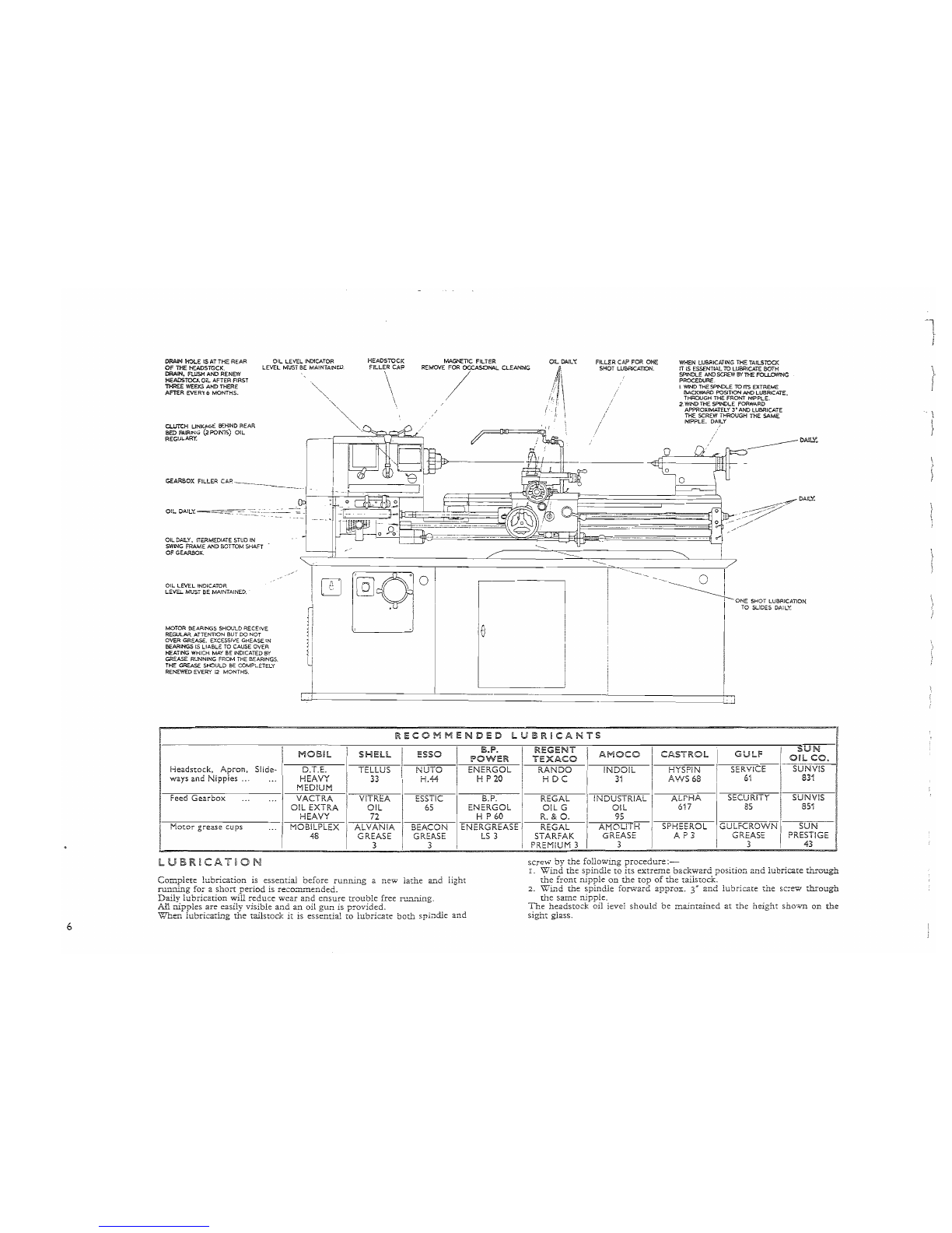
LUBRICATiON
Complete
lubrication
is
essential
before
running
a
new
lathe
and
light
ruIllling
for
a
short
period
is reco:::n.mended.
Daily
lubrication
will
reduce
wear
and
ensure
trouble
free ru.ll.ning.
All
nipples
are
easily
visible
and
an
oil
gun
is
provided.
Wnen
iubricatL.'g
D.'1e
tailstock
it
is
essential
to
lubricate
both
spindle
and
screw
by
the
following
procedure:-
I.
Wind
the
spindle
to
its
extreme
backward
position
and
lubricate
through
the
front
nipple
on
the
top
of
the
taiistock.
2.
WL.,d
the
spindle
forward
approx.
3"
and
lubricate
the
screw
through
the
same
nipple.
The
headstock
oil level
should
be
maintained
at
the
height
shown
on
the
sight
glass.
)\
. \
}
l.
I
The
!Tillin
purpose
of
this
booklet
is
to
provide
users
wit..~
a
full
list
of
par::s,
should
replacements
become
necessary.
When
ordering
spares
please
quote
the
paz-t
number~
description
and
the
LATHE
NUJ\i.BER, wt-.ich
will
be
found
stamped
at
the
tailstock
end
of
the
bed.
Attention
has
been
drawn
to
a
few
points
?lhich
may
be
of
use
to
~he
JtJ
ST
.,~
L L
f~
TEO
t~
Siing;ng:
Holes
are
provided
in
the
base
under
the
~eadstock
and
tailstock
ttuougb.
'.vhich a
oar
IT".1.ay
be
passed.
for
slinging
p1l:poses.
Care
should
be
taken
to
avoid
the
lifting
ropes
bearing
on
the
lead-screw
or
feed
,od.
C~eaning:
.('\11
bright
surfaces
are
covered
'with
an
anti-corrosi~'le
compound
before
despatch
from
the
works.
This
should
be
removed
with
petrol
or
para..f1in
before
putting
the
machine
into
operation.
Leven~i1g:
Because
of
the
rigid
integrated
construction
of
the
bed
and.
canine:
D2se
the
machine
is
inherently
accurate
and
caDable
of
oerfonnance
within
the
specification,
when
it
leaves
the
works.
~
A
The
Iathe
shouid
not
be
boited
down
but
should
be
IO'Y\;'ered
on
to
locating
pins
secured
to
a
rigid
floor
and
the
jacking
screws
adjusted
to
eli-rninate
rock.
By
bolting
JOi;v-n,
distortion
could
occur,
introducing
twist
in
the
bed
and
the
resultant
damage
may
not
be
corrected
by
releasing
the
nuts
on
the
bolts.
It
is
advisable
to
support
the
jacking
screws
on
steel
plates.
The
screws
should
be
ad1usted
::0
enable
the
he3dstock
end
of
the
lathe
being
slightly
higher
than
the
tailstock
end
so
that
the
front
of
the
machine
is
raised
relative
to
the
rear.
This
facilitates
return
of
the
coolant
to
the
Slli"TIp.
Before
despatch
the
machine
has
been
carefully
tested
for
smooth
rUlli-llng
and
accuracy.
(See
test
chart.)
Any
checks
for
accuracy
MUST
be
made
with
I
purchase:
of
a
HHARRISO~"
lathe,
!:J.1.e
observance
of
'yvhicn
will
ensure
satisfactory
se:-'"·lice.
New
developments
and. modil-l.cations
resultL."1g
in
improved
perio:rma...""1c':
ill2y
be
incorporated
from
time
to
tL,Tle
on
them
and
the
right
is reser;red
to
modify
the
specification
as
may
be
:-equired.
the
macr-jne
on
a
rigid
floor.
Ensure
th2t
me
test
mandrels
are
true,
clea..'1.
and
free
from
burrs
on
the
taper
seating.
Clean,
and
inspecr
the
internal
taper
of
the
spindle
before
inserting
the
mandrel.
I
DETAILS
OF
ANI
DISCREPANCY
BETWEEN
THE
TEST
G-1P..RT
AND
YOUR
O~
TESTS
SHOULD
BE
REPORTED
TO
THE
MANUFACTURERS
BEFORE
ANY
ADJUSTMENT
IS
MADE.
EtectdcaJ
connection:
The
supply
wires
should
De
cOffilected
to
L.~e
isolator
switch
at
the
end
of
the
cabinet
in
b.'1e
usual
IT'.:.ar'u·.ler.
~nitiaj
opera.tion:
It
is
important
to
ma...'r.ce
sure
that
t...~e
feed
or sc:rewC"utt:ng
levers
are
in
the
disengaged
position
Defore
operating
the
Lathe
other;:;ise
damage
can
be
caused
by
the
saddle
or
tools
running
into
the
headstock
or
tailstock.
f...!.s
the
headstock
is
the
most
important
unit
of
the
Lathe
only
the
best
IT"A2teriais
and
workmanship
are
incorporated
in
this
assembly.
All
the
gear
teeth
are
induction
hardened
to
45°:500
Brindl
and
honed
to
a
smooth
and
accurate
form.
The
hardening
may
result
in
a
SOline.
of
higher
pitch
than
is
evident
on
a
Lathe
which
does
not
have
hardened
gears.
To
ensure
satisfactory
operation
of
the
bearings
it
is
essential
to
run
in
the
macl1ine
at
lower
speeds
only
duriIlg
the
first
40/50
hours
of
operation.
After
Lhis
initial
run
in
period
we
also
recommend
that
a
further
gradual
build-up
to
the
top
speed
operation
is followed.
7

~f
..
8
FRONT
CiE.AA
saEC1'OR
LEVER.
INTERLOCKED
GEAR
SELES:TORS.
I..OCKli'IG
NUT
FOR
Sffl>IU.
SLIDE.
~ERDIALS.
TAiLSTOCK
ouu.
I..OCKli'IG
LEVER
TAlLSTOCIC
I..OCKli'IG
LEV-at.
FEED
REVERSE
LEVEl'l
GEAR
SELECTOR
LEVE'
\\
LEADSCREW
TORQUE
LlMlTER
~I
'II
,.
'---'i..L--IUl'
I I I
~.
1--
r:.
OR
DOG
CLUTCH.
" : 4
-*
s:;;
...
I
II
(rnWVl'!
'£Jd
'1
I
"'~!
n
FEED
CHANGE
LEVE
}
r~
i (') I
SLIPPiNG
CLUTCH/
/ • i
ISOLATOR.
it
11
1
ELECTRiCAL CONTROL
PANEL./'
i
/
--------------c)!,~
10
V
\,J
I 0 0 [f'j1
!
~'I
i / I
' I
I / I
I
,/
I
oj
I."
/'
J
!
/
/
/
!
I~:~!~i--------------f-------
I
!
I
! I
,
II
r'
.
f'l
V
1
Ii
I I
, !
(~
CLlITO-l
OPERAT!NG
LEVER.
SCREwc.:rTING
iNCXCATOR
[)tAL.
N
\
\
\ I
, I
\1
1
r \
!
",i
~
~
i~
APRON KANUWHEEL.
El
Ii:
I .
i
I
!
o
~-.J
FEEDSHAfT ENGAGING LEVER.
.
MiCROMETER
DtAL.
ThILSTOCK
OPEAATI'IG
HANDI'Il-EEL
TOPSUDE OPERATING
EtALL
KAND'..E.
LEAD5CREW
FEEDSHAFT.
:rHlRD5HAFT
CLlJTCH
OPERATING.
CROSS SLOE OPERATNG
~r-EEL
EADSCREW
ENGAGNG
LEv-:R.
CWTCH
OPERATiNG
LEVER.
SURFACING
I>ND
SLDlNG
FEED
CHANGE KNOB.
'\
I
1

{
L
f
)
All control levers are shown on
the
illustration on the opposite page.
Eiecukai
Controls.
A single panel,
on
the
front
of
the lathe,
contains all
the
electrical controls within easy reach
of
the
operator.
A Dush-button oneratedstarterwithoverload
and
no-voltprotection
is
~tandard
equip'ment
on
all machines;
other
controlsavailable being
two speed, reversing
and
coolant
pump
rotary type switches.
(b)
HeadstocK.
Speed changes should only
be
made when
the
spindle
is
stopped.
The
standard machine incorporates a start/stop
mechanical clutch and brake operated via a
third
shaft by control
levers adjacent to gearbox and apron.
An
alternative electrical
control by similar levers and
third
shaft provides direct reverse to
the
spindle
in
addition
to
forward
and
stop.
A tV\'o-position front gear lever selects
the
high speed range when
in
the
right-hand
position and
the
low speed range
in
the left-hand
position and this, used in conjunction with
the
two position twin
selectors at
the
top
of
the headstock, gives a total
of
eight spindle
speeds" Freely siiding gears combined
"Nith
a direct reading speed
chart ensures effortless and instantaneous speed change.
Forward
or reverse rotation
of
the
feed gear train
is
obtained
by
a selector lever at the front
of
the headstock.
(c)
Norton
Feed
Gear
box.
Thirty-six
changes
of
threads
and
feeds are obtained
by
manipulation
of
the
tumbler
lever
in
conjunc-
tionwith the nvo adjacent compoundgear levers.
The
lever positions
are determined by reference to the direct reading screwcutting
and
feed chart.
For
changewheei combinations see charts on page
12.
An
additional
unit
can be supplied giving lever operated selection
of
English or
Metric
threads. A range
of
I5
Metric
thread pitches
from
0"5
to 7 mm. together with the standard range
of
4 to
60
TPI
is
directly available.
With
the
metric gearbox, 30 metric pitches are available having a
range from
0"2
to
7 mm. pitch. Extra change wheels can be
supplied for Metric/English conversion giving a
thread
range
of
4 to 60
TPI.
Change Wheel combinations are given on page 13.
(d)
Apron.
Instantaneous engagement
and
disengagement to
both
feeds
is
obtained by
the
trip
lever
of
the
drop
Olit
worm box situated
at
the
base
of
the
apron.
The
feed selector knob which
is
directly
below
the
cross slide handwheel should be
pushed
in for sliding
feeds and pulled out for surfacing feeds.
Engagement
of
the
leadscrew for screwcutting is by means
of
the
lever
at
the right
of
the
apron wpich is pulled
up
for engagement
and
pushed down for disengagement. Simultaneous engagement
of
leadscrew and feed
rod
is
prevented
by
interlocking control.
The
carriage may be locked
to
the
bed
by means
of
the hexagon
screw on the
right-hand
side
of
the carriage.
Exact repeat
of
leadscrew engagement
is
obtained with the screw-
cutting
indicator.
On
English models:
To
cut
even threads
per
inch, engage at any graduation.
To
cut
odd
tf-....reads
per
inch, engage
at
any
numbered
graduation.
To
cut
haifrhreads
per
inch, engage
at
graduations I
or
3.
To
cut
quarte:
threads
per
inch, engage
at
graduation
I-
On
Metric
models:
To
cut
·5, ·75,
I,
l"5,
2,
3 and 6 mm. P. engage at any graduation.
To
cut
r·25, 2"5, 5
and
10
mm.
P.
engage at any
numbered
graduation.
To
cut
4 mm. P. engage
at
graduations
60
or
120.
The
indicator dial cannot be used for metric, B.A.
and
other
special threads when a 4
TPI
leadscrew
is
fitted.
It
can be used for metric threads (divisible into
120)
when a 6 mm.
pitch
leadscrew is fitted,
but
not
for special threads, including
English
and
American.
For
all speciai threads
it
is
necessary to
maintain engagement
of
leadscrew and an electrical reversing
switch can be supplied for returning the carriage, enabling repeat
cuts to be taken.
(e) Slideso Cross slide
and
compound slide are fitted with friction
grip micrometer dials graduated to read
"OOI
in.
The
compound
slide assembly
is
arranged
to
rotate
through
360 degrees
on
the
graduated cross slide
and
locking is by means
of
the
two
nuts
on
the
swivel slide.
Micrometer
dials are also available to read
0·02
mm.
(f)
TailstocKo Clamping to
the
bed
is
effected by
the
lever
at
the
rear
and
spindle, quill locking
is
by means
of
the
pad
bolton top
of
the
tailstock.
9

~'--
10
FI
I
SE
F E
operations other than turning are possible
on
a lathe fitted with a few attachments and these
enable further operations ttl be carried out without
The
following attachments are avaiiable for recourse to special machines.
Lathes.
Collet
Attachments.
This
type
of
chuckprovidesa
most
accurate
means
of
gripping
work,
the
accuracy being
0'0005
in.
at
the
collet
nose,
and
0'003
in.
at
a distance 3 in. out.
Use
of
attachments
is
not
restricted to cylindrical work
and
collets
for
square
or
hexagonal
bar
can
be
prov"ided.
(i)
Draw
Tube
Type
CoHet
Attachment
To
fit
the
attachment,
remove chuck or faceplate,
centre
and
sleeve
from
spindle nose. Pass
the
draw
tube
through
the
spindle
from
nose,
then
assemble
hand
wheel
and
clamping
nut
onto
tube.
Mount
the
spindle nose cover
onto
taper
and
secure
with
draw-nut
which is integral with spindle. Assemble
the
closer
bush
into
mouth
of
spindle,
insert
required
size
of
collet
and
screw onto
draw
tube.
The
standard
range
of
collets is
from
16"
to
If'
maximum
in
increments
of
-(5-'7-
but
any
size
within
this
range
(including metric) can
be
provided.
eli)
Mu!tisize
Collet
Attachment.
The
complete assembly
is
mounted
on
the
spindle nose. Collets are
inserted
after
removing
the
closer "bush \vith
the
-v;'Tench
provic.ed.
The
capacity
of
the
attachment
is
1"
to I
~"
and
is coyered
bv
II'
coll~ts.
-
~
Tap~r
Turnir;.g
t;.tta~hme!1t.
~'h.ilst.it
is,
preferr,e?
that
this
att2.cnr;ren~
be
ntt.ea
at
t~e~~jorks,
l1ttl,e
Gl~CU1~y
..
s00Uld
b~
e:p~rl
ence~
Dy
tne
en
4g:neer .WlS?lng to
m~K;
tIns
a.ciOltlc·n
t~t
t?e.latne.
Bolt holes are
drilled
In
tne
rear
01
tne
carr12ge
on
all
lathes
to
acc~pt
the
support
bracket
of
the
attachment
and an
assembly
instruction
draviing
is
supplied
,-vith
each unit.
Taper
TUi"ning
of
lengths
up
to I I in. (297 mm.:; w'ith
included
angles
up
to
20
d~grees
can
be
carried
out,
graduater. scales being f'rovide·2.) :-eading degrees
~t
the
ta~lstock
end
~nd
inche~
taper
per
foot
~:
the
head~t~cK
end.
instrUCtIons for sett1ng
up
p:n
..
OT
to
tap~:-
turning
are
as
10110\\'s
-
Re
'loase
tho
t\"O
~U~C
,~'lam";~~
·i-e
,'-,;,,01
'b~r
on.
~O
t\"o
.................
~
"~-
1.J.
1...:)
....
'1.
~'.I..:lb
l::.~l
.....
_:~
1
......
;.
G,,,
~
::;"_<',
I.
".L.l..1..-
reqUlred
angle
D=\~
means or
the
8.Q}ust.:ng
scre'l,;;:
a1
tne
rear
and
reclaffip. Release
the
t\VO
socket
head
cap screv.rs
at
the
left-band
side
of
the
att2ct:ment
-these
mus:
Temaa).
released
during
taper
turning.
Taper
turning
at
any
point
along
the
bed
can
be
achieved
by
setting
the
support
bracket
at
the
rear
end
of
the
bed
to
the
desired
position.
/w~~
~"
"
rT
{--I
/
~
~~.
/"
,--+j'"
~,
~~
t--4~
~
~
~ ~
;j-<
I
~'-.
---'.-{
,-
s~~
__
_
1'-1
!-.,:
------'3J.+----
-------
.Y.""~
••
~~--~
--~
~
--~_.~:=:--:"-
7:
~~---~
L..:
---:--------::::::::::=.-.
--~
A-
--....,:;;
~
~
~--'
--5
Cb"TRA,.:S!NG
MA>:j:<~
F,S
Y
~i
i:
~
~
;:'9 Z
~
'-""""c
For
set
up
shov:r:
in
Fig~
"y
\vith saddle traversing
In
ciirecti~n
'A'
2~d
set uf_.shoWD
in.
~ig:.
Z
\vit~,
s~ddle
traverSIng
In
GlrectlOn
1)'
1t
IS
adVIsable
to
ellTII1Ilate
~acklas?
b.e~\v~en
cro:s
s~ide
sc;~"v;~.
and~
~U!
b~e~ore
~ngag~ng
~~~
~~~~
~~~:~~~e
c:~L~~t~~~~~n~\~na~~::~:n~\~~Vt~~~l~~
the
correct
:utt':ng
DO~lLj\Jn.
\\:'ith saddle
tra~t"~si:1?
Hi
opposite directions to
tnose
snov\·n. in
Figure~
~-
c~;
Z~
backlash
het"\\Teen
cross
slide
scre\71,~
and
nut
is
removed
no:-m2.1
ad~lancemenI
of
the tooL
Change
0~·Jer
to
normal
turnlIlG
as
fo11oV1S:-
Sct
s\",:ivel
ba:-
to
ze!"0 graduaticn:.
:t~-it~d~a,-;;
5ErpO~::
!J~S.Ck~l
to lailstock
end
0:
bed.
;"
..
Qci~
tne
t\.~·c
soc::et
h:::aC
car
scret;,:s.
M [Hi
ng
.tCa~'!:ach
ment.
"[Iii,.
a.::d~~ncD::
i:.;
mounted
on
to
tbe
COrD.-
pound
s~id~,
replacing
the
lOO~
pr~:<
-rh::
ttt~
<~Jr~cd,
vee
g:-oo\>ed Slide
has
v::.":;:ti:3.:
,,:::::!~'V;
ad!ust:T.
....
'~T
2.I1~~
i'~
3.7"rar~;:...·d
tc;
sv,?ivel
againST
2.
scale
\
,\
}
!,
~.-.--
----
12
sc
E I G
(WITH
ENGUSH
GEARBOX
&-
4 T.p.m.
lEADSCREW)
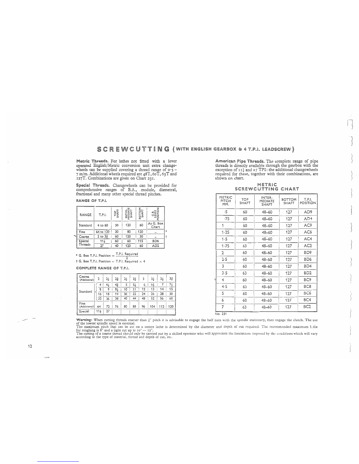
Metric
Threads.
For
lathes not fitted with a lever
operated English/Metric conversion unit extra change-
wheels can be supplied covering a thread range
of
0'5
-
7 m/m. Additional wheels required are
48T,
60T,
63T
and
I27T. Combinations are given on Chart 231.
Special
Threads.
Changewheels can be provided for
comprehensive ranges
of
B.A., module, diametral,
fractional and many other special thread pitches.
RANGE
Of
T.I".!.
Ii
0...1:;:
'I
"'~I:;:
16
1:;:
I
."'6
0<
"'-<
f-<
cow-
RANGE T.P.L
f-l:
~8l:
til:
0G:;~
'Ion,
-:LV>
",V>
-'2
1---
-----1
Standard 4
to
60
30 120 I 60
As,...G
h· Box
i----'
________
1
'-
art
Fine I64
to
120 30 80 I120 "
Coarse I 2
to
3i
60 I 120 I 30
Spedal I
11t
60 1
60
115 BD6
Threads
27
1"4O'1~,
60 AD2
*
" t
* G B T
Pie
't'
_ T.P.1. Required
.
ox
. .
.•
OSI
Ion
- 2
t G. Box T.P.I. Position = T.P.I. Required X 4
COMPLETE
RANGE
OIF
T.P'!.
Coarse I
II
1
II
3
"I
3'
1 I 1 3
(Additional)
2 2"
2.
~
2"
_3_
~ ~
~
r
l 4 I.<LL 44 5 I
52-
6
6'
7 7.l
Standard
1'<
13
1-'~-1-9-;-
-1-0-1::::1::::~::::
-1-2-
-1-~-
-1-4-
-1-~-
!~I~I~I~i~~~I~~
1----'
l32
,~i~'~!~I~~I~I~
Fine I i I
'1
! I
(Additional)1
64 i
7:
.~i
..
80
!~II'~I.~~~
S
pedal
i
11
i I
21
i I
!.
I
American
Pipe
Threads.
The
complete range
of
pipe
threads is directly available through
the
gearbox with
the
exception
of
I I
-~
and
27
TPI:
the
additional changewheels
required for these, together with their combinations, are
shown
on
chart.
METRiC
SCREWCUTTING
CHART
, MEIR.lc I
TOP
I INTER· \ BOTTOM
P~~~
SHAFT MEDIATE SHAFT
SHAFT
I I
·5
60
48-60 I
127
I
I
·75
60
48-60
127
I I
1 I
60
48-60
127
I I I
,
I I
1·25
60
48-60 I
127
I
1·5 I
60
I 48-60 I
127
1·75 1
63
I 48-60
127
I
2 I
60
48-60 I
127
2·5
60
48-60
127
I
1
3 I
60
I 48-60 1
127
I
3·5
I
63
48-60 I
127
4 I
60
I 48-60 I
127
4·5
I
63
I I
I 48-60 I
127
I
5 I
60
1 48-60 I
127
I 1 I
I
i , i I
6 I
60
I 48-60 !
127
I~-
1 I 1
I
63
48-60 i
127
I
I
No.
231
T.P.L
POSiTION
AD9
AD4
AC9
AC6
AC4
AC2
BD9
BD6
BD4
BD2
BC9
BC8
BC6
BC4
BC2
Warning:
When
cutting
threads
coarser
than
f'
pitch
it
is
advisable
to
engage
the
half
nuts
with
the
spindle
stationary,
then
engage
the
clutch.
The
use
of
the
lowest
spindle
speed
is essentiaL
The
maximum
pitch
that
can be
cut
on
a
centre
lathe
is
determined
by
the
diameter
and
depth
of
cut
required.
The
recolTilllended
maximum
r.~!ix
for roughing is
go
and a light cut up to
I00
-
12°.
The
cutting
of
a coarse
thread
should
only
be
carried
out
by
a
skilled
operator
who
will
appreciate
the
limitations
imposed
by
the
conditions
which
will
vary
according
to
the
type
of
material,
thread
and
depth
of
cut,
etc.
"\
j
J
sc
E I
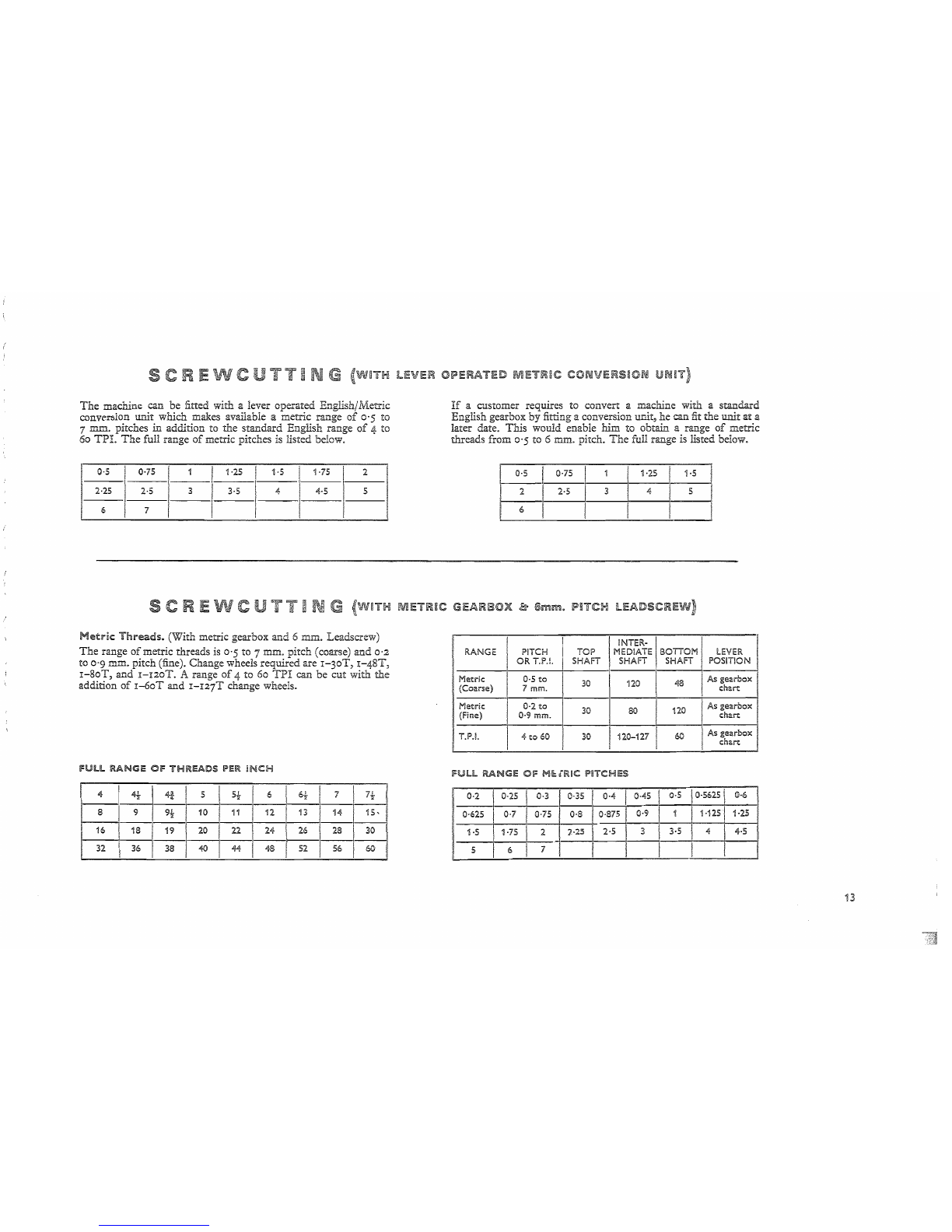
The
machine can be fitted with a lever operated English/Metric
conversion unit which makes available a metric range
of
0'5 to
7 mm. pitches
in
addition to the standard English range
of
4 to
60
TPI.
The
full range
of
metric pitches is listed below.
0·5 I 0·75 1 I 1·25 I 1·5 I 1·75 2
, I I
2·25 2·5 3 I 3·5 4 4·5 5
I I
6 7 I
sc
E I
Metric:
Threads.
(With metric gearbox and 6 mm. Leadscrew)
The
range
of
metric threads
is
0'5 to 7 mm. pitch (coarse) and
0'2
to
0'9
mm. pitch (fine). Change wheels required are
I-30T,
I-41ST,
I-SoT,
and
I-DOT.
A range
of
4 to 60
TPI
can be cut with
the
addition
of
1-6oT
and
r-I27T
change wheels.
fULL
RANG!:
Of
THREADS
PER
INCH
4
~"1~5!1'
6!-
I 7 I
7!,
8 9 9t1 10
-1-1
-1---:j2
--1--'1-
13 I 14 I
15,'
16
1.
I
19
120l
22 24
26~~
32 36 I 38
~
44 48 52 56 60
lEVER
OPERATED
METRIC
CONVERS~ON
If
a customer requires to convert a machine with a standard
English gearbox by fitting a conversion umt, he can fit the unit
at
a
later date.
This
would enable him to obtain a range
of
metric
threads from 0'5 to 6 mm. pitch.
The
full range is listed below.
0·5
075
'±H
15
I
2
251'
4~
6 I I
METRIC
GEARBOX
.&
6mm.
PITCH
lEADSCREW)
I I !NTER-
RANGE PITCH
TOP
MEDIATE BOTTOM I
LEVER
I
OR
T.P.I. SHAFT SHAFT SHAFT POSITION
Metric
I 0·5
to
30
no
48
As
gearbox
(Coarse)
7 mm.
chart
Metric
0·2
to
30
80
120 iAs
gearbox
(Fine) 0·9
mm.
chart
T.P.1. 4
to
60 30 120-127 I 60 As
gearbox
chart
fUll
RANG!:
Of
Hi:; lIftiC
PITCHES
0·2
0-25 0·3
~I
()-4
I0·45 0·5 0·5625 \ 0·6
0·625
(J.7
0-75 I 0·8 I0·875 I 0·9 1 1·1251 1·25
I I
1·5
1·75 2
12-25
2·5 3 3·5 4 4·5
5 6
71
I
13
$.
.......
_ ...
14
I
Periodic
inspection
with
adjustment
where
necessal")'.
as
given
below,
will
ensure
that
this
lathe
retains
its
original
high
standard
of
accuracy
and
periormance.
Drive
Belts.
The
drive motor is mounted on a platform inside
the
cabinet base. Adjustment to
the
vee belt tension is
by
a screw at
the
rear
of
the machine.
Procedure for replacing vee belts is as
follows;-
Remove the drive guard
and
inspection cover from end
of
cabinet base.
Release tension
in
belts by adjusting screw at rear.
Replace belts
and
carefuIIy re-tension.
It
is important to ensure
that
the belts do not slip
as
this would
only increase both pulley and belt wear.
Clutch.
If
slip occurs then adjustment
is
as
foHows;-
Open the drive guard.
Increase the spring load by slightly rotating the
nut
(anti-
clockwise, i.e. left-hand thread) on the end
of
the
dutch
shaft.
Constant operation
of
the
dutch
results eventually in wear
on the driving faces (usually signified by the
dutch
refusing
to drive) and the following adjustment will be necessary.
Stop the motor, leaving the
dutch
in
the
ON
position.
Remove the fairing (at the rear
of
the bed, beneath the
headstock).
Release the outer
nut
on the operating linkage one
complete turn and
re-damp
with inner nut.
The
dutch
should be dismantled at six-monthly intervals
and any lubricant on the driving faces removed by washing
in paraffin.
Headstock
Spindle
Bearings.
Adjustment for wear on the
Timken taper roBer bearings on the main spindle
is
as
follows:-
Remove headstock cover.
TE
E
Release locknut (by turning anti-clockwise, i.e. R.H. thread)
and rotate adjusting
nut
sufficiently to obviate play,
then
re-
tighten locknut.
It
must
be
emphasized
that
this operation
requires
the
utmost care
as
over-tightening can seriously
impair
the
life
of
the bearings.
Sealing compound should be used when refitting the head-
stock cover.
The
magnetic plug (chromed head) which is fitted
in
the
headstock cover
must
be
occasionally removed
and
cleaned
of
any particles
of
steel which may have collected there.
Always replace
the
magnetic plug after cleaning.
Saddle
Adjustment.
To
adjust the rear strip release the four
nuts on the underside
of
the strip, adjust the headless set s.:rews
by turning clockwise
and
re-lock the nuts.
To
adjust the front
strip, release the caphead screw which secures the adjusting screw
and
rotate the latter anti-clockwise,
re-damp
the caphead screw.
Care should be taken to avoid over adjustment.
Cross
Slide
Adjustment.
Take up
of
wear on the taper gib
strip
is
by releasing the locknut, adjusting the screw and
re-locking the nut.
The
gib strip is
of
a length to aliow adjustment over a range
of
wear
but
after a
number
of
adjustments
it
may be necessary to
shorten the screw.
Top
Slide. Adjustment to the strip
is
by releasing the locknuts,
ti[htening the screws
and
re-locking the nuts.
E!ectric
..!
Controis.
All electrical control equipment
is
mounted
on the panel at the front
of
the cabinet and
if
removal is required
it
is I
N.cP
ORT
ANT
to ensure that the isolating switch (line switch)
is
in
the
OFF
position.
The
isolating switch (line switch)
MUST
NOT
be removed until the mains leads have been isolated.
~
(
t
E
Whena
componentis requiredto bemachinedonalathe,
the
following
principal points
must
be settled:
(r)
the
manner
in
which
the
work
should
be
mounted;
(2) the tool set-up to be employed;
and
(3)
the
speeds and feeds
to
be employed.
Turning
between
Centres.
This
method
of
turning necessitates
centre holes being drilled
in
both ends
of
the
work.
The
operation
should
be
performed
by
a special drill givingacountersink
of
60 deg.
angle to suit the lathe centres,
the
centre drill
bei..'1g
held
in
a drill
chuck
mOUJ."1ted
i.11
the
tailstock spindle with
the
workheld
in
achuck.
It
is usual practice
to
carry
out
a facing operation on
the
end
of
the
workpiecebeforecentre-drillingand
itis
essential
that
workoverhang
from chuck jaws, for
both
facing
and
drilling operations, should
be
a
minimum, to ensure concentricity. Centre drills are delicate tools
and easily broken, largely owing to lack
of
sensitivity
in
feeding
the
drill,
and
to work speed being too low.
To
prevent breakage use a
high speed
of
work revolution and a very fine feed.
Wit.1J,
the work mounted between centres,
and
fitted with a driving
dog
and
with
t.1Je
tailstock centre we111ubricated,
it
is
important
that
the
work should befree enough to
turn
by
hand
but
withoutany
end
movement. Owing
to
heat generated
by
the
cutting action,
the
work
expands during machining,
and
if
screwed
up
tightly before cutting
commences,
the
result is
that
the centre
end
maybecomeoverheated
causing damage
~o
both
centre and work.
When using carbide turning tools, the work speed may be so high
that damage to a dead centre may take place however
much
care is
used.
It
is better
then,
to use a revolving centre which rotates with
the
work, and
is
not
therefore affected
by
high work speeds.
Tool
Settings.
Correct tool setting
1S
Important, for accurate
grinding
of
tool angles
is
of
no avail
if
the
tool is improperly set
in
relation
to
the work. While normally
the
tool
point
should
be on
the
centre line
of
the
work, a setting slightly above
centre
is permissible,
L E I E
but
a setting below centre may cause slender work to deflect and
spring
on
the top
of
the tool and out
of
the
centres.
For
all taper
turning
and
screw cutting operations,
it
is essential
that
the cutting
edge
of
the tool be mounted exactly on
the
centre line
of
the work,
oti!erwise discrepancies in taper and thread form
will
result. A
simple way to obtain correct tool height is by setting to one
of
the
lathe centres.
For
parting-off operations, use a tool with a rigid shank and with
the overhang from the toolpost kept to a minimum.
The
cutting
edge
must
be set on the work centre and square to the lathe axis.
Do
not
attempt parting-off unless
the
work is well supported ar.
..
ensure
that
overhang from the chuck is
not
excessive.
Chuck
Work.
When a chuck
is
not
in
use
it
should not be left so
that
cast iron
dust
or other cuttings may enter the bore or parts
of
the
mechanism.
The
bore may be protected by plugging with a
doth,
nevertheless before mounting the chuck on the lathe spindle,
dean
the bore
of
the
chuck and the spindle nose and lubricate with
Molybdenum Disulphide a tube
of
which,
is
supplied with the
machine.
When mounting or removing a chuck, protect the slides
of
the
bed
with a piece
of
wood upon which to rest the chuck before lifting
it
onto
t..'1e
spindle nose. When tightening the chuck jaws, never try
to obtain increased gripping power
by
lengthening
the
arm
of
the
box key.
For
second operation work, or for work which may be'difficult to
hold by standard jaws, the use
of
soft jaws shaped
as
required will
often prove a time saving factor and ensure greater accuracy.
When setting work in an independent four-jaw chuck, make use
15
;l~
1!\iL_
16
R E
COM
MEN
D E D l A
THE
P
RAe
T
~
C
E-(
ell)
i1 t d • }
of
the
setting rings
on
the face
of
the
chuck
to
obtain
an
approxi-
mate location.
It
is
then a simple matter to make
the
final adjust-
ment
for
,~eater
accuracy.
fa.cepla.te
Work.
The
remarks
in
regard to
the
mounti.'1g
of
chucks apply equally to faceplates
and
catch plates. Some castings
or
forgings are so shaped
as
to be difficult to hold
in
a chuck,
but
can
be
damped
on a faceplate by straps
and
bolts utilising the holes
and
slots provided,
but
do not rely entirely
upon
these. Whenever
possible use stops against the work to take
the
pressure
of
the cut.
An angle plate bolted on to the faceplate,
on
to which the work is
mounted,
is
often useful for boring
and
facing operations. Always
ensure that revolving work
is
securely fastened
and
that
a balance
weight is fitted to counteract the out-of-balance effect
of
the
mounting units and work.
Use
of
Steadies.
Long slender work,
if
unsupported between
centres, will tend to whip or
bend
under
pressure
of
the cutting
action.
To
preven~
tl-,is
happening, a travelling steady should be
employed~
When machir:ing black bar, first turn a short length
of
W.~e
bar at the tailstock end to
the:
diameter required, and adjust the
STeady
jRWS
to
touch the
v;~ork,
then lock them in position.
The
javls will then support the
v.;ork
at the point
of
the
cut
all
along the
length. Keep
javls
\vell lubricated during the operation.
A stationary steady can be set up at any point along the
bed
to
support 2 long shaft.
If
the shaft is
or
black barJ a ring
somew<hat
wider than the
of
the res: must be turned
as
a bearing for the
jaVys.
If
the
shaft
is
slender, this
can
be a delicate operation, so that
a sharp pointed. tool with 2 very light cut should
be
employedQ
Another use
of
a stationary steady is when
an
operation requires
to
be
performed
on
the
end
of
a bar.
In
such instances
the
distance
from
the chuck
may
be
too great for machining to take place
without additional
support,
and
if
drilling is required,
the
tailstock
centre is
not
available.
Thus
to
support
L~e
work
by
means
of
a
steady, adjust
the
jaws to
touch
the
work until
it
is
running
true,
and
then
lock
them.
Again, use plenty
of
oil between
the
steady
jaws and
the
revolving work.
DI"i!iing
and
Reaming
from
the
Taiistock.
For
theseoperations
the
work is gripped
in
a chuck or
mounted
on
a faceplate.
It
is
important
L,1.at
the drill
be
started
true
so
that
z..
hole concentric
with the
\~,Tork
diameter is produced, and a common method
em-
ployed to attain this
is
by
centre drilling before commencing normal
drilling.
The
limitation
of
a twist drill
as
a cutting tool is
that
it
follows its
OVln
point which takes
the
line
of
least resistance. Incorrect
grinding
can
cause additional inaccuracies
by
Cr)
cutting edges
being ground to different angles, (2) cutting edges
of
equal angles
but different lengths, (3) ::utting edges
of
unequal angles and
lengths causing the point to be off-centreo It is essential then to see
[hat the radial components
of
the two cutting edges are equal so
that
they constrain
the
drill to follow a direct
path,
but
if
an
accurate bore is required, a drilled. hole should be enlarged
by
a
single point tool and final size obtained
by
reaming~
Straight shank reamers are
held
in
a chuck,
vFhile
taper sha.nks may
be inse:-ted into the tailstock
spindlea
The
reamer should
be
fed
carefully through the hole
by
rotation
of
the tailstock handwheel,
usmg an
ampk
supply
of
lubricant when reaming steel.
1
RECOMMENDED
LATHE
PRACT~CE-{c(H'd(L)
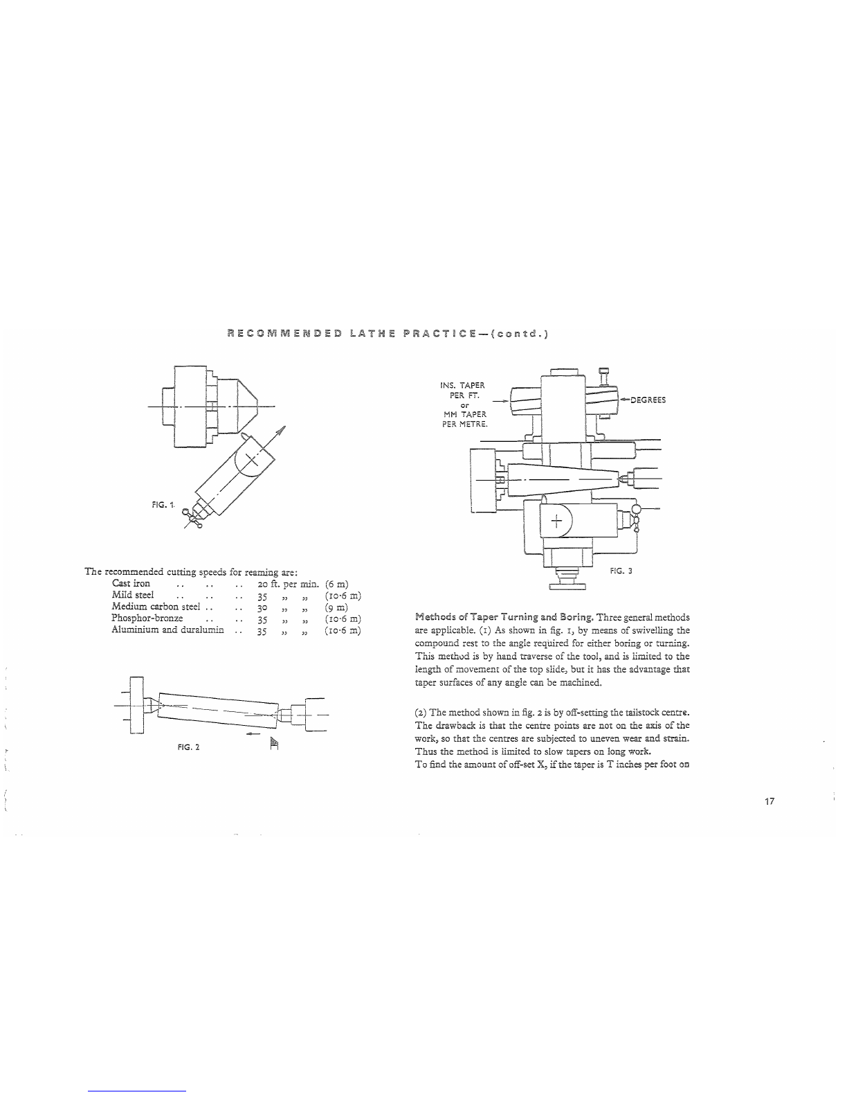
F!G.1
The
recommended cutting speeds for reaming are:
Cast iron
20
ft.
per
min.
Mild steel
35
" "
Medium carbon steel
Phosphor-bronze
Aluminium
and
duralurnin
30 " "
35
" "
35
" "
~
r--
--l
--_I
n
I
~
----==~
~:JEtt
FIG.
2
-~
(6
m)
(ro·6
m)
(9
m)
(10'6
m)
(ro·6
m)
r==J
I
INS. TAPER
~
PER
FT.
_ !
or
I
...
MM
TAPER.
PER
METRE.
~
FIG.
3
Methods
of
Taper
Turning
ami
Boring.
Three
general methods
are applicable. (x)
As
shown in
fig.
I,
by means
of
swivelling the
compound rest to the angle required for either boring or turning.
This
method is by hand traverse
of
the tool, and is limited to
the
length
of
movement
of
the top slide,
but
it
has the advantage
that
taper surfaces
of
any angle can
be
machined.
(2)
The
method shown
in
fig.
2
is
by off-setting the tailstock
centr~.
The
drawback is that the centre points are not on the axis
of
the
work, so
that
the
centres are subjected to uneven wear and strain.
Thus
the
method is limited to slow tapers on long work.
To
find the amount
of
off-set X,
if
the taper is T inches per foot
on
17

18
R
Ii:
COM
M
Ii:
N D
Ii:
D
LA
T H
Ii:
P
RAe
T
~.
C
Ii:
- ( © 0
1m
t d . )
..2'
..2
, •
~
t..'
L'
h h X T
xL.
h
..
lameteran
..
lengtn
or
WOb.
1S
'
mc
es, t en =
---me
es
24
or
To
find the amount
of
off-set X,
if
the
taper is T mm.
per
metre
TxL
mm.on diameterand length
of
work is L mm.,
then
X
2,000
lfthe
induded
angle
oftaperis
e,
X = L x
tan~
inches (mm.).
2
(3)
If
the lathe
is
fitted with a taper turning attachment,
fig.
3,
then
more accurate tapers, either external or internal, can be produced
than
by
the two preceding methods.
By
the use
of
this attachment,
the
lathe centres are
not
of
course taken out
of
alignment,
so
that
the bearing surfaces are unaffected.
LATHE
TOOLS
In
mounting turning tools
in
the rest, the tool should only
~xtend
the minimum amount from the rest
to
obtain the maximum support
against the downward pressure
of
the cut.
For
damping
'the tool,
ample pressure
is
provided
wit.'iJ.
the spanner supplied, ane' on no
TOP RAKE ANGLE
--!
,i
\,
\!
,.
rI
~\
~,
J
j
FRONT
CLE..A,RANCE
ANGLE
TABI..IE 1
Cutting
Angies
foe"
1-1.5.5.
and
Cemented
Cae"bkie
Tool$
Materials H.S.S.
Cemented
Carbide
Top
Rake
Clearance
Top
Rake
Clearance
Mild
steel
20°
6°
go
4°-f>°
High
carbon
steei
10° 4°
3°-4
0
4°-6
Q
Soft cast
iron
10°
go
"c-S0
4°-f>°
Chilled
iron
..,
ao
4° (;0 2°-4°
Copper
'12°
1Co
13°
4°-6
0
Brass ..,
0°-6
0 i 0°
3°
4°-6
0
Aluminium
30°
10°
i&~
6c-s0
TAla:"'!: 2
Cutt~ng
Speeds
In
feet
per-
m[;r£~~t~
(mffZtlres
pe~
n'~r~~)
Materiai
H.S.S,
Teols
Cemer:ted
Carbide
Roughing
:-in1shing
Roughing
Fini:hing
fl:.
roo
ft. m.
ft.
m.
ft.
rn.
Mild Steel
'130
40 200
61
200
61
300
91
High
carbon
steel
45
14
60 18 200
6-,
400 122
Soft
Ca'it
iron 60
18
75
23
200
6';
350 107
Chilied
iron
...
'10
3
15
4-5 is
4·5
30
9
Copper
200
6~
200
6~
4')0 122 700 213
Brass .. _ 250 76 400 122 400 122 700 213
Aluminium
300
91
.jDa
122 500
~
52 ,000 3051
TABLE
3
;Feeds
in
Enches
per
fre¥otut~on
(mm.
per-
revoh.rdon)
Material N.S.S. and Cemen.ted
Caib~de
Too:s
Roughing
Fi:lishing
lncnes
mm.
inches
mm.
Mild
steel
.(rlO ·254 -007
·178
High carbo?:
St:;t;
010 ·254 ·007
·i78
Soft
cast
!r'on ·013 ·330 008 ·203
Chilied
:ror, -003 ·203 ·005 ·127
COPDer
-020 -508
-OOB
·203
B~~
...
.~.~
·~m
Aluminium
·0'13
·330 -007 ·178
1
~

RECOMMENDED
LATHE
IPRACT~CE-(contd.)
account should extra pressure
be
applied
by
lengthening
the
leverage
by
dubious means
such
as a piece
of
piping.
Such
methods
are unnecessary,
and
cause damage
not
only
to
the
damping
screws,
but
the
entire
compound
rest.
Boring tools may
be
of
one piece solid forged,
or
may comprise
cutter
inserts fixed
in
a
boring
bar. A
point
of
note
in
regard
to
the
grinding
of
boring tools is
that
the
conditions governing
the
top
rake
and
clearance angles are different
from
those
in
turning,
so
that
a secondary
dearance
is
required
for
the
front
of
the
tool to
clear
the
enveloping curve
of
the
bore.
Speeds
and
feeds.
The
cutting
speed
is expressed
in
surface feet
per
minute,
and
is
the
speed
at
which
the
surface
of
the
work passes
the
tip
of
the
tool.
If
D is
the
diameter
of
the
work
in
inches, N
the
workspeed
in
r.
p.m.,
and
S
the
cutting
speed
in
feet
per
minute,
then
3.82 x S 318 x S (Metres/min.)
N
or
N = D
mm
The
feed
rate
is expressed
in
inches
per
revolution
of
the
headstock
spindle.
The
time
to complete one cut,
in
minutes, can
be
calculated from
Length
of
cut
(in.)
or
(mm)
Spindle
speed
(r.p.m.)
x feed (in.
per
rev.)
or
(mm
per
rev.)
FIG. 4
DEPTH
OF
CUT
FIG.
5
DiRECTION
OF
TOP SLlDE TRAVEL
Tables
I,
2 and 3 give suitable tool angles, cuttingspeeds,
and
feeds
for a range
of
the
common engineering materials.
Screwc!.Itting.
For
cutting
vee threads the top
of
the
tool is placed
at
centre height,
having been previously ground to
the
required shape without any
top
rake.
Note
that
if
the
tool is given
top
rake
the
plan angle
ofthe
tool is
not
the
angle
that
will be reproduced
in
the
work.
Fig. 4 shows
the
use
of
a settinggauge for
both
external
and
internal
threading,
but
when cutting vee threads with
the
tool set
in
this
manner,slowspeedsandlightfeeds arenecessarybecause
the
cuttings
cannot be free flowing without
top
rake
on
the
tooL
Thus
a
better
method
for cutting external vee threads is shown
in
fig. 5 where
the
compound
slide
is
swung around so
that
the
tool is fed
in
at
an angle
of
slightlyless
than
half
theincludedangle
of
the
thread
(i.e. approxi-
mately 26 deg. from normal, i.e. 64 deg. on cross slide graduations,
19
L=-._
20
RECOMMENDED
LATHE
IPRACTmCE-{contd.)
when cutting standard
55
deg. threads) so that metal is mostly re-
moved by the left-hand side
of
the
tooL Side rake can be provided
so that heavier cuts can be taken and the chips
flow
easily away.
In
commencing a screwcutting operation, take a light trial cut
and
check the number
of
threads per inch by measuring with a rule
or
screw pitch gauge.
Then
proceed by taking successive cuts until the
full depth
is
reached. Check for depth and accuracy by means
of
the
nut
to fit the screw, or by a thread gauge
of
the ring type.
Tapered threads may be cut by means
of
a taper attachment or by
off-setting the tailstock.
In
either case the tool must be set square to
the work axis, and not to the tapered portion.
Square
Threads.
This section
of
thread
is
often used for multiple
threadedscrews,andtheterms
"pitch"
and
"lead"
shouldbe under-
stood. Pitch
is
the distance from a point on one screw thread to a
correspondingpointon the nextthread,measuredparallelto theaxis.
Lead
is
the distance that a screw thread advances axially in one turn.
Thusona
singlethreadedscrew
the
termsareidentical,
buta
notation
such
as
i in. pitch, ! in. lead, would indicate a two start screw,
and
to produce this,
the
gearbox would require to give a saddle move-
ment
of
! in. for every revolution
of
the
spindle, while
the
tool
would be ground to produce t in. pitch section
of
thread.
The
procedure when cutting a multiple start screw is to set
the
top slide
parallel with lathe axis and cut the first thread
in
the
usual
manner
at
the correct
LEAD.
Cut
subsequent threads
by
advancing
the
top slide each time a distance equal to
the
lead divided
by
the
number
of
starts. This,
of
course, applies to
aU
multiple
threaded
screws regardless
of
thread section.
Acme
and
Worm
Threads.
The
procedure to
be
adopted for
Acme and worm thread cutting is similar to
that
recommended for
vee threads except for the setting angle
of
the
compound slide.
In
this case the thread
induded
angle is 29 deg. so that a slide setting
of
apProx. I3 deg. from normal (i.e. 77 deg. on cross slide
graduations) would be appropriate.
Full depth
of
an Acme thread is 0'5 P +
o'or
in.
and
width at
bottom
is
0'37°7 P - 0'0052 in. where P is
the
thread pitch.
)
)
~

FITTn\lG
AND
USE
OF
ATT
eH
ENTS-(contd.)
graduated
45 degrees each side
of
the
vertical centre line.
An
arbor
for
mounting
between centres
and
driven by
the
lathe driver piate is
available to take I in. bore cutters.
Machining
bythis means is, how-
ever, restricted
to
thin
work
and
so, wherever possible, face
or
end
milling is recommended. Face
and
end
mills togetherwith
Woodruff
key cutters can be provided having morse
taper
shanks for direct
fitting to
the
spindle nose.
Mining
and
Gean::utting
Attachment.
As
in
the previous case,
this
attachment
is
mounted
on
the comDound slide
in
place
of
the
rooIpos!.
On
the vertical slide assembly:
of
similar construction to
the milling
attachment,
is fitted a
support
for
the
work
arbor
together
with indexing mechanism.
Cutter
arbor
add
cutter
are
mounted
be-
tween
the
lathe centres, the drive
being
by driver plate
and
pin.
It
is
important
that,
when setting
up
for gear
cutting,
the
work
arbor
be
exactlyat
right
angles to
the
cutter
arbor
and
the
cutter
directly
under
the centre line
of
the
work arbor. Gears
up
to 7 in. diameter can be
cut
and
cutters covering a wide range
of
gear pitches are available.
Dividing
Attachment:.
Accurate indexing
of
the lathe spindle
is
achieved by use
of
this attachment. Work
mounted
in the chuck,
on
faceplate or between centres can be indexed for operation such
as
graduating, slotting, key seating, etc.
The
attachment
fits on the
top
changewheel shaft after removal
of
the gear,
the
hinged guard
re-
maining open whilst
in
use. A very wide range
of
divisions is possible
withthe
standard
indexplate,
but
special plates canbe provided
when
necessary.
Boring
Table.
This
attachment
fits directly
on
to
the saddle. A
boring
bar
with six cutters for usc between centres can be supplied.
To
fit
the
table, remove the complete cross slide
by
turning
the
handwheel until the slide becomes free
and
can
be
taken from
the
rear
of
the
carriage. Replace by the boring table, feeding on to
the
screw which is
operated
in
the reverse direction. Place the
boring
bar
between
the
lathe centres
and
drive by means
of
the
driver plate.
FQurway
Toolpost:.
It
is
self
indexing
and
positively located.
This
unit
replaces the
standard
type tooIpos!.
American
Toolpost.
Of
the recognised American
pattern
with
swivelling base plate
and
single
clamp
screw.
CQolant
Pump.
The
electric
pump
unit is housed inside the
cabinet base
and
access
is
through the louvre
at
the
R.H.
end
of
the
cabinet.
Feed
StQPs.
(i)
Micrometer
Carriage
Stop.
Clamps to the front vee bed
way
and
used for accurate machining
of
shouldered work.
The
screwed spindle
is
fitted with a micrometer dial
having
O'OOI
in.
or
'02
mm.
graduations.
Four
Position
Carriage
Stop.
Similar to the above, this
unit clamps to the front vee
bed
way
and
is used for
multi-
shouldered work.
The
indexingbody contains four adjustable
screws each
of
which can be used in
turn
to control various
shoulder lengths.
(iii)
Cross
SEde
Stop.
Is located on the cross slide ways
and
is
used
en
facing operations.
Bed
Turret.
This
attachment
is
clamped to the bed ways replacing
the tailstock.
It
comprises a lever operated slide
of
4in. stroke
length
with a six station automatically indexing turret, each station having
an adjustable stop screw. Supplied with the lathe, the
turret
head
is
bored
suitable for I in. diameter tool shanks
but
otherwise is left
solid for boring
in
situ to ensure perfectalignment withtheheadstock
centre.
This
attachment
cannot be used with an extended cross
slide or with hydraulic copying equipment.
Cut-off
Slide.
Used
for parting off and facing operations.
This
quick acting lever operated slide, with front and rear toolposts, is
clamped to the
bed
ways immediately in front
of
the chuck.
Additional
Equipment.
A wide selection
of
equipment available
includes chucks
of
all sizes within the capacity
of
the lathe, t?ilstock
drill chuck,rotating centre,
half
centre, pipe centre,
turning
tools
and
tool holders, etc.
Two
Speed
Equipment:.
Spindle speed ranges can be doubled by
fitting a two speed
motor
and selector switch.
The
standard is 34 to
1500
r.p.m.,
but
other
ranges can be provided.
11

l
ES
R P
The
eq-:Jip:nen! comprises an independently ope:-ated rear tool
sEc.;~
5.:ted
:0
a
h:;.'"G.!."2Ulic:l1y
Dpe:-ated
angle slide, the
'Nhole
being
rr:o~~t~::
:}11
ar:
:::~tcnded
crCJss
slid;:.
(P.~
front compound slide
is
also
:J.tTe:d
rer :1or=al
tu.rTIing.~'
_;etomatic copying control from the
te:np!atc to
F~he
hydraulic slide is
by
iTIeanS
of
a stylus arm,
mounted
a~
:;:p~r
ro11::::
b~ariDgs1
actuating a spool
"type
valve.
::::.,';:~~~~;;~i..t::
s,\..1pport
~1e2ds
.~nd
slide
are
mounted
011
:he
rear
of
the
jeG.~
GI:t
of
the heads
ha\'~ng
8.
graduated eccen:ric sleeve to give
'se:
;Jv~r~
'Nh'~n
:equ.ired.
Both
heads
can.
be
loc:zed in any position
alorrg
the slide, the
Ce:1IieS
of
each being adjustable
by
a handwhee1.
eii
~S
.~~:.:pplied
the pl.::rrr u::it ::s
....
L3.11y
piac~d
OIl
Ihe
PE
R
TI
T::?>lPLATES
AND
COMPONENT
8U~d'~1{S
'The circular templates arc usually produced exactly similar
-co
the
finished work,
and
often
the
first
batch
of
components
is
used
2~
~he
i:emplate.
It
is
important
that
the
template
has a good surface
finish,
otherv~7ise
irregularities
~~t;ill
be
transmitted to the
\~lork
piece
and for more accurate reproduction best results are obtained with
a
hardened
and
ground
template.
For
work
oflarge
diameter, a smaller overall
diameter
tempLate may
be
used
providing
the
profile
and
lengths are
the
same.
It
is
important
that
the
lengths
of
the
component
blanks be slflliiar
and
the
ends
centre
drilled to a
constant
depth
to
ensure
uniforrr,Jt:
of
shoulder
lengths
throughout
the
batch.
PREPARATION
AND
SETTING
UP
(Fig.
6)
The
oil container
should
be
filled with
the
recommended
grade
of
hydraulic
oil
and
t..'he
level always
maintained
between
the
end
and
Fll
E I E
floor at the tailstock
end
of
the machine.
The
unit
comprises
an
oil
container, flange
mounted
moter and geared
pump
~YVith
pressure
relief
valveo
Three
fte:o-ible
hoses connect
the
pump
unit to
the
hydraulic sEde, these being pressure, return
a~d
drain
lines~
C:opy
turning is carried out
vvith
the teoI in the normal upright
position;
an
electrical reversing s\vitcn facilitating quick change-
over from normal
turTIing~
The
.llmerican type, key drive,
long
tape: nose headstock spindle ensures complete protection and
positive drive
in
both
directions
of
rotation.
M Ii,.::-
~:I~leter
saddle stop controls the
movement
ot the
carnageG
the
maximum
level shown on the dipstick.
The
end
fittings
of
the
pressure,
return
and
drain hoses are
numbered
I,
2
and
3 respectively,
and
care must
be
taken
to
ensure
that
these
are connected to the fittings
on
the
attachment
and
oil container
bearing corresponding
numbers.
Connection
of
the
electrical leads
to
the
hydraulic
pump
motor
should
be
such
that
the
direction
of
rotation
is anti-clockwise
when
viewed
from
above.
Before commencing copy turning,
the
hydraulic
pump
unit
should
be
run
for a few rninutes
and
the
hydraulic slide fed in
and
out
2
few times
by
means
of
the
hand
control lever
to
allow
the
oil
to
circulate quite freely
through
the
system.
This
should
apply
when-
ever
the
m2chine has
been
idle for
any
length
of
time.
The
oil
pressure reading
on
the gauge
should
be
150
lb.
per
sq.
inch
approximately,
21
Popular Lathe manuals by other brands


Atrump
Atrump AL32 Operation & maintenance manual

Grizzly
Grizzly G0456 Parts Breakdown

Record Power
Record Power CL3-CAM Original instruction manual

Axminster Craft
Axminster Craft AC355WL Original instructions

HARVEY
HARVEY JIB W0903X instruction manual

Axminster
Axminster WORKSHOP AW205WL Original instructions