The tail stock can be fastened on the lathe bed by tightening the
locking block through one locking handle, there is a sleeve in the tail
stock, the taper of it is MT3, there is another locking handle which can
tight the sleeve at any position, when you rotate the hand wheel of the
tailstock, the sleeve can be moving.
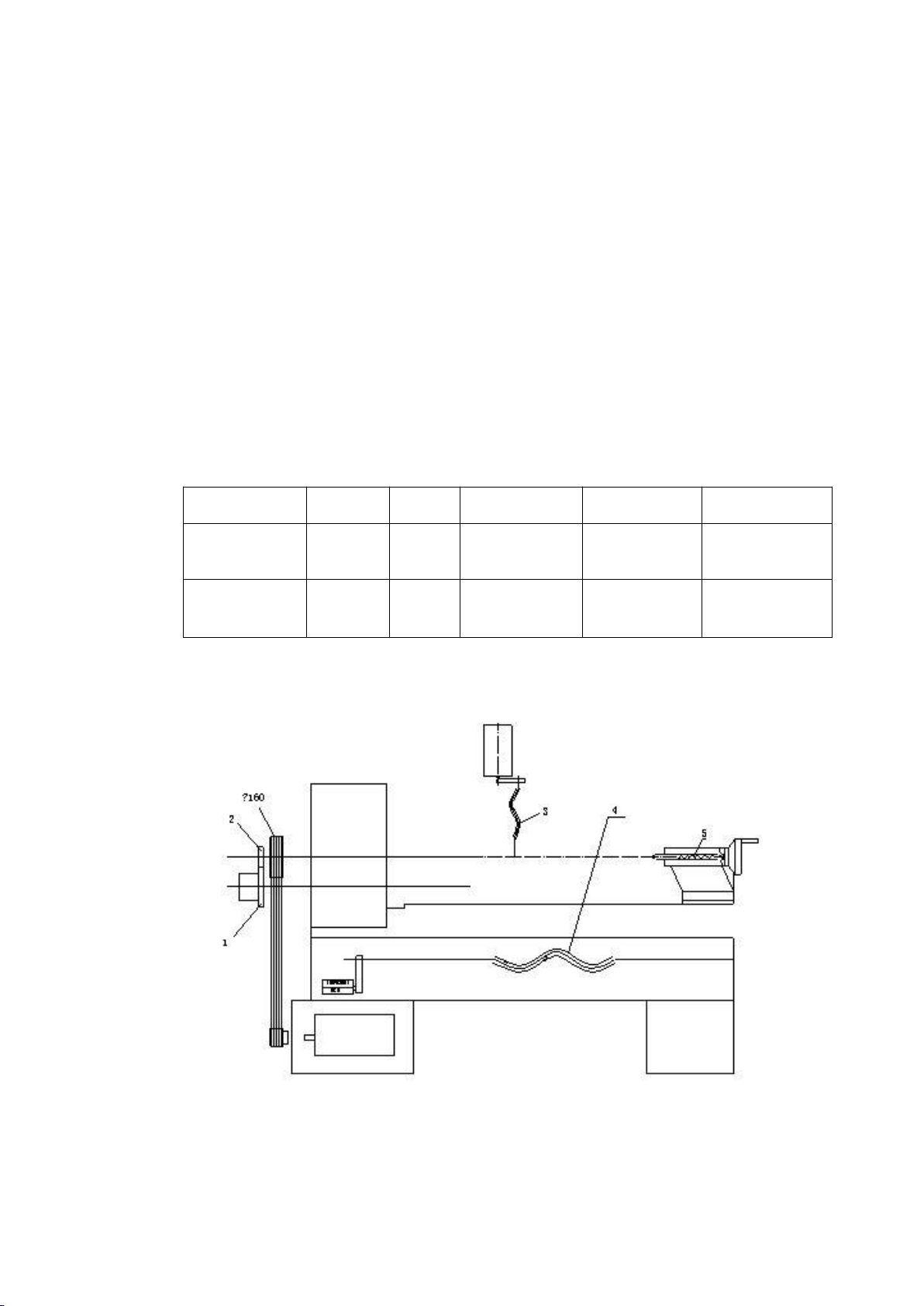
6. THE TRANSMISSION SYSTEM
THE MAIN SPINDLE SPEED ROTATION
The speed of spindle is transmitted by triangular belt, the motor
(YL100-4) will get the different speeds through the frequency
converter, so the main spindle speed will be changed with it.
THE MOVEMENT OF LONGITUDINAL FEEDING
The longitudinal feeding of the cross slide is supported by the step
motor(110byg5500) fixed on the lathe bed, the longitudinal feeding
speed will be changed by controlling the lead screw speed.
THE MOVEMENT OF CROSS FEEDING
The longitudinal feeding of the cross slide is supported by the step
motor(110byg5500 or 90BYG3502) fixed on the cross slide, the
cross feeding speed will also be changed by controlling the lead
screw speed.
To ensure for the spindle to run a circle while the tool post to move a
lead, so we fix a photoelectric encoder on the left side of the
headstock, the speed proportion from the spindle to photoelectric
encoder is 1:1, the photoelectric encoder will coordinate with the
step motor or serve motor to ensure for the spindle to run a circle
while the tool post to move a lead (that is, the thread pitch to be
processed), it saves trouble to change gears and the thread
processing ranges are also widened.