Hart Scientific 1502A User manual


a
WARNING
To ensure the safety of operating personnel, and to avoid damage to this equipment:
DO NOT operate this unit without a properly grounded, properly polarized power cord.
DO NOT connect this unit to a non-grounded, non-polarized outlet.
DO USE a ground fault interrupt device.
WARNING
To ensure the safety of personnel, and to avoid damage to this equipment:
DO NOT use this unit in environments other than those listed in the user’s manual.
Follow all safety guidelines listed in the user’s manual.
WARNING
CALIBRATION EQUIPMENT SHOULD ONLY BE USED BY TRAINED PERSONNEL.

Table of Contents
1 Introduction. . . . . . . . . . . . . . . . . . . . . . 1
2 Specifications and Environmental Conditions . . . 3
2.1 Specifications . . . . . . . . . . . . . . . . . . . . . . . 3
2.2 Environmental Conditions . . . . . . . . . . . . . . . . 4
2.3 Warranty . . . . . . . . . . . . . . . . . . . . . . . . . 4
3 Safety Guidelines . . . . . . . . . . . . . . . . . . 7
4 Quick Start . . . . . . . . . . . . . . . . . . . . . . 9
4.1 Unpacking . . . . . . . . . . . . . . . . . . . . . . . . 9
4.2 Power . . . . . . . . . . . . . . . . . . . . . . . . . . . 9
4.3 Connecting the Probe. . . . . . . . . . . . . . . . . . . 9
4.4 DC Power Option . . . . . . . . . . . . . . . . . . . . 10
5 Parts and Controls . . . . . . . . . . . . . . . . . 13
5.1 Front Panel Buttons . . . . . . . . . . . . . . . . . . . 13
5.2 Rear Panel . . . . . . . . . . . . . . . . . . . . . . . 14
6 General Operation . . . . . . . . . . . . . . . . . 15
6.1 Selecting Units . . . . . . . . . . . . . . . . . . . . . 15
6.2 Parameter Menus . . . . . . . . . . . . . . . . . . . . 15
6.3 Menu Lockout . . . . . . . . . . . . . . . . . . . . . . 15
6.4 Selecting the Probe Characterization . . . . . . . . . . 17
6.4.1 Setting the Probe Characterization Type . . . . . . . . . . . . 17
6.4.2 Setting the Characterization Coefficients . . . . . . . . . . . . 17
6.4.3 ITS-90 PRT and Coefficients . . . . . . . . . . . . . . . . . . 18
6.4.4 Callendar-Van Dusen (RTD) Conversion . . . . . . . . . . . . 20
6.4.5 IPTS-68 Conversion . . . . . . . . . . . . . . . . . . . . . . 20
6.4.5.1 Setting the Characterization Coefficients . . . . . . 21
6.4.5.2 Testing the Coefficients . . . . . . . . . . . . . . . 21
6.5 Filtering . . . . . . . . . . . . . . . . . . . . . . . . . 21
6.6 Setting the Current . . . . . . . . . . . . . . . . . . . 22
6.7 Power Saver. . . . . . . . . . . . . . . . . . . . . . . 22
7 Digital Communications Interface . . . . . . . . . 23
7.1 Serial Interface . . . . . . . . . . . . . . . . . . . . . 23
7.1.1 Setting the Baud Rate. . . . . . . . . . . . . . . . . . . . . . 24
7.1.2 Automatic Transmission of Measurements . . . . . . . . . . . 24
7.1.3 Time Stamp and System Clock . . . . . . . . . . . . . . . . . 24
7.1.4 Duplex Mode and Linefeed . . . . . . . . . . . . . . . . . . . 25
7.2 GPIB Interface. . . . . . . . . . . . . . . . . . . . . . 25
7.2.1 Setting the Address . . . . . . . . . . . . . . . . . . . . . . . 26
7.2.2 Setting the Termination Character . . . . . . . . . . . . . . . 26
7.2.3 Time Stamp . . . . . . . . . . . . . . . . . . . . . . . . . . . 26
i

7.3 Remote Commands . . . . . . . . . . . . . . . . . . . 26
7.3.1 Measurement Commands . . . . . . . . . . . . . . . . . . . 26
7.3.1.1 Reading Temperature . . . . . . . . . . . . . . . . 28
7.3.1.2 Automatically Transmitting Measurements. . . . . . 29
7.3.1.3 Selecting the Unit of Measurement . . . . . . . . . 29
7.3.1.4 Enabling the Time Stamp . . . . . . . . . . . . . . 29
7.3.1.5 Setting the Clock . . . . . . . . . . . . . . . . . . . 29
7.3.2 Probe Characterization Commands. . . . . . . . . . . . . . . 29
7.3.2.1 Selecting the Characterization . . . . . . . . . . . . 29
7.3.2.2 Testing the Characterization . . . . . . . . . . . . . 30
7.3.3 Sample Commands . . . . . . . . . . . . . . . . . . . . . . . 30
7.3.3.1 Setting the Filter . . . . . . . . . . . . . . . . . . . 30
7.3.3.2 Setting the Probe Current . . . . . . . . . . . . . . 30
7.3.3.3 Setting the Power Saver . . . . . . . . . . . . . . . 31
7.3.4 Communication Commands . . . . . . . . . . . . . . . . . . 31
7.3.4.1 Setting the Duplex Mode . . . . . . . . . . . . . . . 31
7.3.4.2 Setting the Linefeed Option . . . . . . . . . . . . . 31
7.3.5 Calibration Commands . . . . . . . . . . . . . . . . . . . . . 31
7.3.5.1 Entering the Password . . . . . . . . . . . . . . . . 31
7.3.5.2 Setting the Menu Lockout . . . . . . . . . . . . . . 31
7.3.5.3 Setting the Calibration Coefficients . . . . . . . . . 32
7.3.5.4 Setting the Serial Number . . . . . . . . . . . . . . 32
7.3.6 Other Commands . . . . . . . . . . . . . . . . . . . . . . . . 32
7.3.6.1 Instrument Identification . . . . . . . . . . . . . . . 32
7.3.6.2 Reading a List of Commands . . . . . . . . . . . . 32
8 Calibration Procedure . . . . . . . . . . . . . . . 33
8.1 Accessing the Calibration Parameters . . . . . . . . . 33
8.2 Calibration Procedure . . . . . . . . . . . . . . . . . . 34
9 Maintenance . . . . . . . . . . . . . . . . . . . . 35
10 Troubleshooting . . . . . . . . . . . . . . . . . . 37
ii

iii
Figures and Tables
Figure 1 Connecting a four-wire probe . . . . . . . . . . . . . . . . 10
Figure 2 12 V DC power source polarity . . . . . . . . . . . . . . . 11
Figure 3 1502A Front Panel . . . . . . . . . . . . . . . . . . . . . 13
Figure 4 1502A Back Panel . . . . . . . . . . . . . . . . . . . . . 14
Figure 5 Parameter Menu Structure . . . . . . . . . . . . . . . . . 16
Table 1 Matching Certificate Values to 1502A ITS-90 Coefficients . 18
Table 2 Setting Coefficients Rtpw, a5, and b5. . . . . . . . . . . . 19
Table 3 Setting Coefficients Rtpw, a8, b8, a4, and b4. . . . . . . . 19
Table 4 Setting Coefficients R(273.16), a6, b6, c6, and d . . . . . . 20
Figure 6 Serial Cable Wiring . . . . . . . . . . . . . . . . . . . . . 23
Table 5 Command List. . . . . . . . . . . . . . . . . . . . . . . . 27
Table 5 Command List Continued . . . . . . . . . . . . . . . . . . 28

1 Introduction
The Hart Model 1502A is a low-cost high-accuracy digital thermometer readout
designed to be used with 25Ωand 100ΩRTDs and SPRTs. Its unique combi-
nation of features makes it suitable for a wide variety of applications from labo-
ratory measurement to industrial processes. Features of the 1502A include:
•Measures 25Ωand 100ΩRTDs and SPRTs
•Four-wire connection eliminates lead resistance effects
•Accuracy: 0.006°C at 0°C
•Resolution: 0.001°C
•Fast one-second measurement cycle
•Adjustable digital filter
•Accepts ITS-90 characterization coefficients
•Also accepts Callendar-Van Dusen and IPTS-68 coefficients
•Adjustable excitation current
•Displays temperature in Celsius, Fahrenheit, or Kelvin or displays resis-
tance in ohms
•Password protection of critical parameters
•Large, bright eight-digit LED display
•Serial RS-232 interface standard; IEEE-488 GPIB interface optional
•Detachable power cord
•Optional 12 V DC power
•Light weight, small and portable
•Sturdy, reliable construction
1502A Manual Rev. 952801 1
1 Introduction

2 Specifications and Environmental
Conditions
2.1 Specifications
Specifications
Resistance Range 0Ωto 400Ω, auto-ranging
Resistance Accuracy, one
year1
0Ωto 20Ω: 0.0005Ω
20Ωto 400Ω: 0.0025% (25 ppm) of reading
Resistance Accuracy, short
term1, 2
0Ωto 30Ω: 0.0005Ω
30Ωto 400Ω: 0.0015% (15 ppm) of reading
Temperature Range3–200°C to 962°C (–328°F to 1764°F)
Temperature Accuracy1, 3, 4 –100°C: 0.004°C
0°C: 0.006°C
100°C: 0.009°C
200°C: 0.012°C
300°C: 0.015°C
400°C: 0.018°C
500°C: 0.021°C
600°C: 0.024°C
Temperature Coefficient of
Resistance1
1 ppm/°C
Resistance Resolution 0Ωto 20Ω: 0.0001Ω
20Ωto 400Ω: 0.001Ω
Temperature Resolution 0.001°C
Probe Nominal R(0.01°C): 25Ωto 100Ω
RTD, PRT, or SPRT
Probe Connection 4-wire with shield, 5-pin DIN connector
Maximum acceptable lead re-
sistance
100Ω
Probe Characterizations ITS-90 sub-ranges 4, 6, 7, 8, 9, 10, and 11
IPTS-68: R0,α,δ, a4, and c4
Callendar-Van Dusen: R0,α, δ, and β
Probe Excitation Current 0.5 and 1 mA , reverses every 0.25 seconds
Measurement Period 1 second
Digital Filter Exponential, 0 to 60 seconds time constant (user-selectable)
Communications RS-232 serial standard
IEEE-488 (GPIB) optional, conforms to IEEE-488.1, capability
AH1, SH1, T6, L4, DC1
Display 8-digit, 7-segment, yellow-green LED; 0.5 inch high characters
Clock accuracy, typical 0.01%
Operating Temperature
Range
Full accuracy: 16°C to 30°C
Absolute: 0°C to 55°C
AC power 115 VAC ±10%, 50/60 Hz, 10 VA, nominal
230 VAC ±10%, 50/60 Hz, 10 VA (optional)
Detachable power cord
DC power (optional) 10 to 14 VDC, 1 A maximum
(220 mA typical, normal mode; 120 mA typical, power saver
mode)
Size 5.6 inches (14.3 cm) wide x 7.1 inches (18.1 cm) deep x 2.4
inches (6.1 cm) high
Weight 2.2 lb. (1.0 kg)
1502A Manual Rev. 952801 3
2 Specifications and Environmental Conditions

1Accuracy specifications apply within the recommended operating temperature range. Accuracy
limits are increased by a factor of the temperature coefficient outside this range.
2Short-term accuracy includes nonlinearity and noise uncertainties. It does not include drift or cal-
ibration uncertainties.
3The temperature range may be limited by the sensor.
4Temperature accuracy is for the 1502A only. It does not include probe uncertainty or probe char-
acterization errors.
2.2 Environmental Conditions
Although the instrument has been designed for optimum durability and trou-
ble-free operation, it must be handled with care. The instrument should not be
operated in an excessively dusty or dirty environment. Maintenance and clean-
ing recommendations can be found in the Maintenance Section of this manual.
The instrument operates safely under the following conditions:
•temperature range: Absolute 0–55°C (32–131°F); Recommended
16–30°C (61–86°F)
•ambient relative humidity: 15–50%
•pressure: 75kPa–106kPa
•mains voltage within ±10% of nominal
•vibrations in the calibration environment should be minimized
•altitude does not effect the performance or safety of the unit
4 Manual Rev. 952801 Hart Scientific
2 Specifications and Environmental Conditions

1502A Manual Rev. 952801 5
2 Specifications and Environmental Conditions

3 Safety Guidelines
•Operate the instrument in room temperatures between 16–30°C
(61–86°F) (recommended). Allow sufficient air circulation by leaving at
least 3 inches of space between the thermometer and nearby objects.
Note: Accuracy specifications apply within the recommended operating
temperature range. Accuracy limits are increased by a factor of the tem-
perature coefficient outside this range.
•The thermometer is a precision instrument. Although it has been designed
for optimum durability and trouble free operation, it must be handled with
care. The instrument should not be operated in wet, oily, dusty, or dirty en-
vironments.
•The instrument can measure extreme temperatures. Precautions must be
taken to prevent personal injury or damage to objects. Probes may be ex-
tremely hot or cold while connected to the thermometer and when re-
moved from the heat source. Cautiously handle probes to prevent
personal injury. Carefully place probes on a heat/cold resistant surface or
rack until they are at room temperature.
•Use only a grounded AC mains supply of the appropriate voltage to power
the instrument. The thermometer requires less than 1 amp at 115 VAC
(±10%), 50/60 Hz and 230 VAC (±10%), 50/60 Hz.
•Optional DC power of 10 to 14 V DC with 1 amp maximum.
•If a mains supply power fluctuation occurs, immediately turn off the instru-
ment. Power bumps from brown-outs and black-outs can possibly dam-
age the thermometer. Wait until the power has stabilized before
re-energizing the instrument.
1502A Manual Rev. 952801 7
3 Safety Guidelines

4 Quick Start
4.1 Unpacking
Unpack the thermometer carefully and inspect it for any damage that may
have occurred during shipment. If there is shipping damage, notify the carrier
immediately.
Verify that the following components are present:
•1502A Thermometer
•Extra Probe Connector
•Power Cord
•Manual
•Probe (optional—must be purchased separately)
•Battery Pack (optional—must be purchased separately)
4.2 Power
Your 1502A is configured for either 115 VAC (±10%) operation or 230 VAC
(±10%) operation. Be careful to only connect the 1502A to a mains supply of
the correct voltage. Otherwise, the instrument may be damaged. The required
voltage is indicated on the back of the 1502A. The 1502A may draw up to 10
VA. The IEC type power cord connects to the back of the 1502A. The cord
must be plugged in to a grounded outlet. The power switch is located at the
back of the 1502A.
When the 1502A is powered on, wait briefly while it initializes. It will then begin
measuring and displaying temperature.
Because of the quality of the components used in the 1502A, it exhibits nearly
negligible drift as it warms up. The warm-up drift is typically less than 5 ppm.
Nevertheless, to ensure the best accuracy and stability, you may want to allow
the 1502A to warm up for ten minutes before use.
Accurate measurement requires that the probe be connected properly to the
input and the correct probe characterization set.
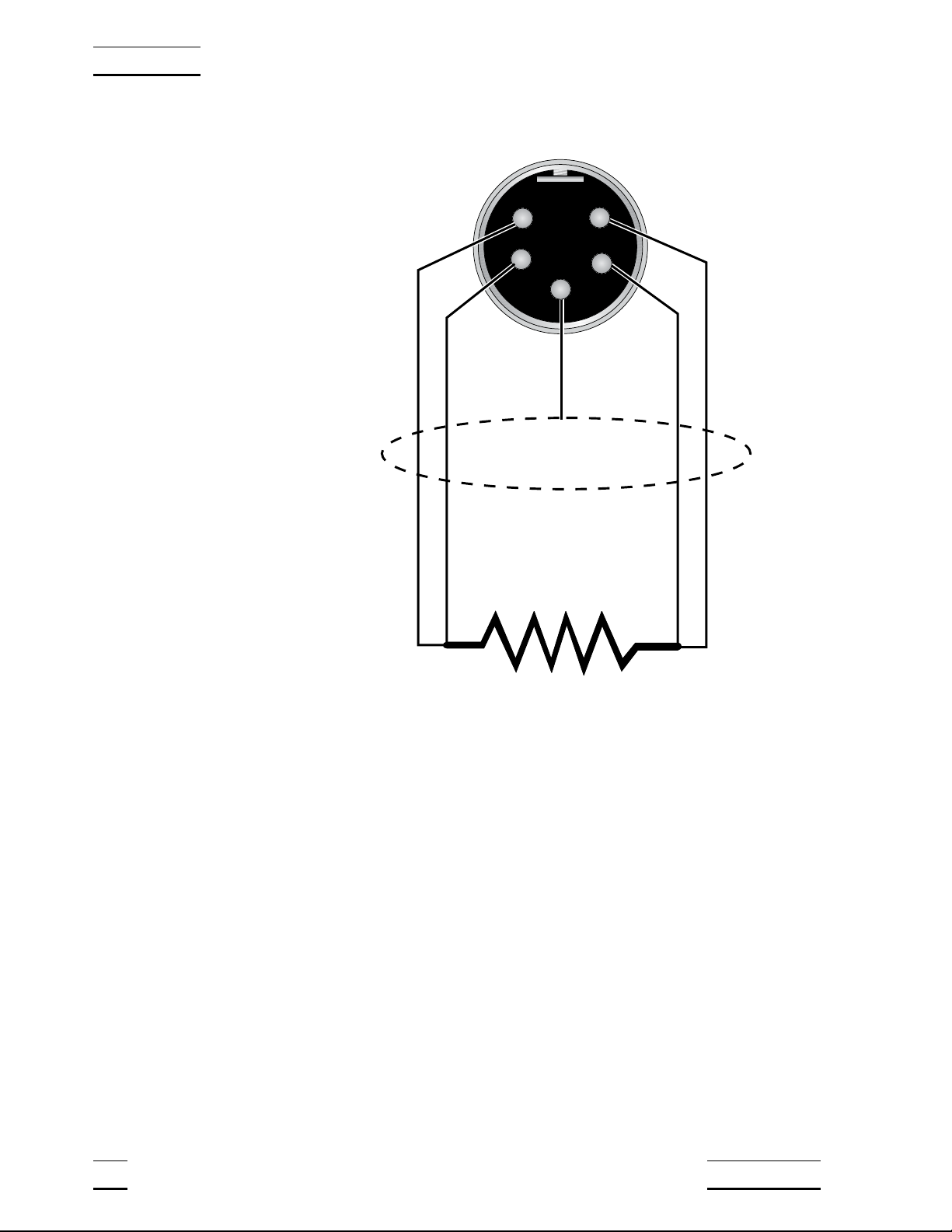
4.3 Connecting the Probe
The RTD or SPRT probe connects to the back of the 1502A using a five-pin
DIN plug. Figure 1 shows how a four-wire probe is wired to the five-pin DIN
connector. One pair of wires attaches to pins 1 and 2 and the other pair atta-
ches to pins 4 and 5. (Pins 1 and 5 source current and pins 2 and 4 sense the
potential.) If a shield wire is present it should be connected to pin 3.
A two-wire probe can also be used with the 1502A. It is connected by attach-
ing one wire to both pins 1 and 2 of the plug and the other wire to both pins 4
and 5. If a shield wire is present it should be connected to pin 3. Accuracy may
be significantly degraded using a two-wire connection because of lead resis-
tance.
1502A Manual Rev. 952801 9
4 Quick Start
4.4 DC Power Option
With the DC power option (Model 2502) installed the 1502A can be powered
from a 12 V battery or other 12 V DC power source. The DC power socket is
located on the rear panel of the 1502A above the AC power jack. The 1502A
accepts a 7/32 inch diameter, two-conductor DC power plug such as
Switchcraft® PN. 760. Observe the correct polarity as shown in Figure 2. The
outside conductor is positive and the inside is negative. The AC power switch
on the rear panel of the 1502A will not switch the DC power.
The optional Model 9313 Battery Pack, available from Hart Scientific, can be
used as a portable power source for the 1502A. It includes a 1.2 amp-hr 12V
sealed lead-acid battery, a DC power cord that plugs into the 1502A’s DC in-
put, a carrying bag, and a battery charger. The battery pack can provide four
to ten hours of operation with each charge depending on whether the power
saver feature is enabled (see Section 6.7).
10 Manual Rev. 952801 Hart Scientific
4 Quick Start
1
24
5
RTD Sensor
Probe Connector
3
Shield
Figure 1 Connecting a four-wire probe

To recharge the battery, disconnect the battery’s plug from the 1502A and plug
it into the mating connector from the battery charger. Attach the charger’s AC
plug into an AC supply of the proper voltage (normally 100 to 125V AC, 50/60
Hz; optionally 200 to 230V AC, 50/60 Hz.). The charger takes about six hours
to fully charge the battery. The charger will stop charging automatically when
the battery is full.
Certain precautions must be observed with the battery and charger. These de-
vices can present safety concerns if misused or damaged. To avoid the risk of
electric shock or fire do not use the charger outdoors or in a dusty, dirty, or wet
environment. If the cord, case, or plug of the charger is damaged in any way
discontinue its use immediately and have it replaced. Never disassemble the
charger. The battery may contain chemicals that are hazardous. To avoid the
risk of exposure to dangerous substances or explosion, immediately discon-
tinue use of the battery if it leaks or becomes damaged. Never allow the bat-
tery to be shorted, heated, punctured, dropped, or squashed. Store the battery
where it will not come into contact with metal or fluids that might short circuit
the battery and where it will be safe from excessive temperatures. When no
longer usable the battery must be recycled. The battery may be returned to the
seller for recycling. Do not dispose the battery in a landfill. Never dispose the
battery in fire as there is danger of explosion which may cause injury or prop-
erty damage.
1502A Manual Rev. 952801 11
4 Quick Start
+
–
Figure 2 12 V DC power source polarity
5 Parts and Controls
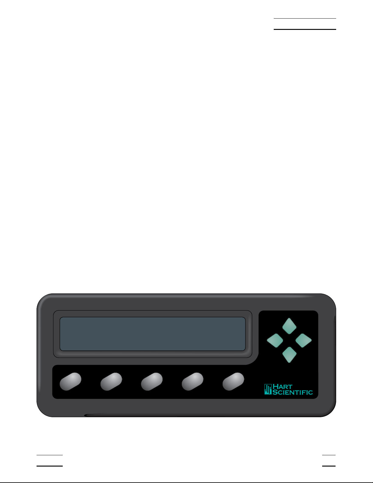
5.1 Front Panel Buttons
See Figure 3.
The front panel buttons are used to select units of measurement, access oper-
ating parameters, and alter operating parameters. The function of each button
is as follows:
C/Probe—This button selects units of degrees Celsius. In conjunction with the
Menu button, it selects the probe parameter menu.
F/Sample—This button selects units of degrees Fahrenheit. In conjunction
with the Menu button, it selects the sample parameter menu.
K/Comm—This button selects units of Kelvin. In conjunction with the Menu
button, it selects the communication parameter menu.
Ω/Exit (Cal)—This button selects resistance in ohms. While editing a parame-
ter, it cancels the immediate operation and skips to the next parameter. If the
Exit button is pressed for more than one-half second the menu is exited. In
conjunction with the Menu button, it selects the calibration parameter menu.
Menu/Enter—This button allows one of the unit/menu buttons to select a
menu. When editing a parameter, it accepts the new value and skips to the
next operation.
Land R—When editing a numeric parameter, these buttons move be-
tween digits. The selected digit flashes.
Uand D— When editing a parameter, these buttons increase or decrease
the value of the parameter or a selected digit.
1502A Manual Rev. 952801 13
5 Parts and Controls
1502 A
C
Probe
F
Comm
K
Sample
Ω
Exit
Menu
Enter
84.981 C
Figure 3 1502A Front Panel
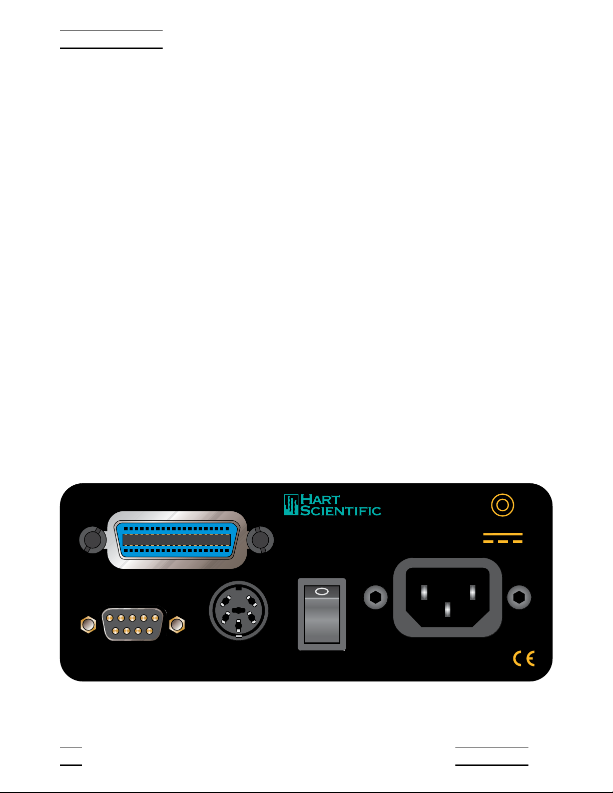
5.2 Rear Panel
See Figure 4.
Serial Port - The DB-9 connector is for interfacing the thermometer to a com-
puter or terminal with serial RS-232 communications.
Probe Connector - At the rear of the thermometer is the probe connector. The
probe must be connected for operation.
Power Switch - The power switch is located on the rear of the thermometer.
The AC power switch turns the unit on and off. It does not control the DC
power.
Power Cord - At the rear of the calibrator is the removable power cord that
plugs into a standard 115 VAC grounded socket. (230 VAC optional)
DC Power - The DC power, located on the rear of the thermometer, powers
the unit immediately when connected.
IEEE-488 Port (optional) - The GPIB connector is for interfacing the thermom-
eter to a computer or terminal with IEEE-488 communications.
14 Manual Rev. 952801 Hart Scientific
5 Parts and Controls
RS-232
IEEE-488
PROBE
POWER
Made in USA
AMERICAN FORK · UTAH 84003 12V 1.0A
–+
l
0
Figure 4 1502A Back Panel

6 General Operation
This section explains basic operation of the 1502A Thermometer.
6.1 Selecting Units
Temperature can be displayed in degrees Celsius (indicated with “C”), degrees
Fahrenheit (indicated with “F”), or Kelvin (indicated with “A” for absolute). The
resistance of the sensor can also be displayed (indicated with “o” for ohms).
Simply press the appropriate unit button, C, F, K, or Ωto select the units.
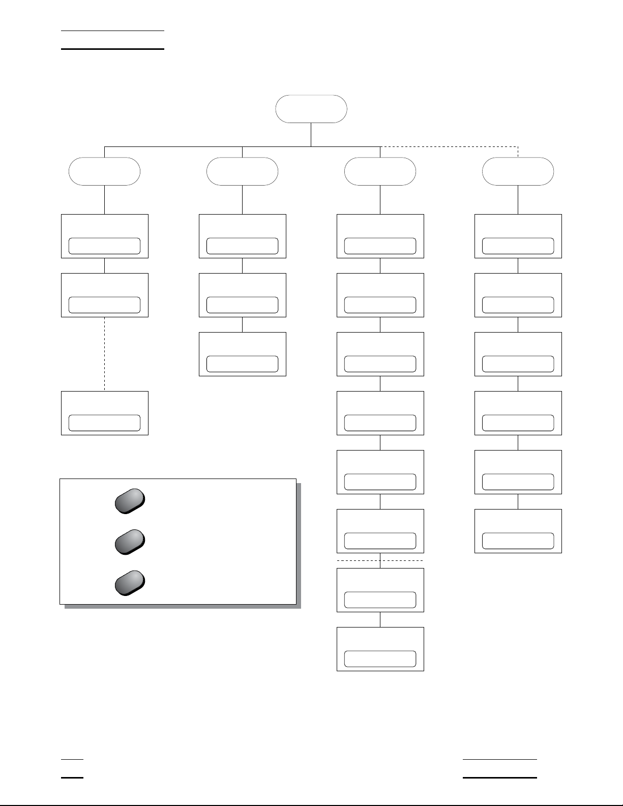
6.2 Parameter Menus
Except for unit selection, all functions and operating parameters are accessed
and edited within the parameter menus. There are four menus: the Probe pa-
rameter menu, Sample parameter menu, Comm (communication) parameter
menu, and Cal (calibration) parameter menu. The arrangement of parameters
in the menus is shown in Figure 5 on page 16.
Menus are selected by pressing the Menu/Enter button followed by the appro-
priate menu selection button. The name of the menu will briefly appear on the
display. For example, the Probe menu is selected by pressing the Menu/Enter
button (“SEt?” appears on the display) followed by the C/Probe button
(“ProbE” appears). Selecting the Cal menu requires that you press the
Menu/Enter button then press the Ω/Exit button and hold it down for at least
one second.
The Probe menu contains parameters for selecting the probe characterization
and setting the characterization coefficients. These parameters are explained
in Section 6.4. The Sample menu contains parameters for setting the filter and
excitation current. These are explained in Sections 6.5 and 6.6. The Comm
menu contains communication parameters such as the serial baud rate or
IEEE-488 address. These are explained in Sections 7.1 and 7.2. The Cal
menu contains the calibration parameters. These are explained in Section 8.1.
6.3 Menu Lockout
All menus can be locked out to prevent inadvertently changing parameters. By
default, only the Cal menu is locked out. The lockout option is accessed in the
Cal menu (see Section 8.1 “Accessing the Calibration Parameters”).
If menus are locked out you must enter the correct password (“2051”) to gain
access. After you select the menu (see the previous section) the display will
show “PA= 0000” and allow you to change the number to the correct pass-
word. Use the Land Rbuttons to move between the password digits and
the Uand Dbuttons to increase or decrease the value of a digit. Press En-
ter when all the digits are correct. If the password is entered correctly the first
parameter in the menu will appear.
1502A Manual Rev. 952801 15
6 General Operation
16 Manual Rev. 952801 Hart Scientific
6 General Operation
Menu
Sample Comm (Cal)Probe
Set clockSet filterSet probe type Enter password
Set time stampSet currentSet coefficients Set menu lockout
Set baud rateSet power saver Set CAL0
Set sample periodTest conversion Set CAL 100
Set duplex Set CAL 400
Set linefeed Factory reset
Set GPIB address
Set GPIB EOS
11.23.30FI= 4Pr= t90 PA= 0000
ts= OFFCur= 1.0 LO=CaL
2400 bPS= OFF -0.0006
00.00.01100.0000 +0.0128
duP=FULL -0.0011
LF= ON rESEt?
Add= 22
E= LF
Press after changing a parameter
Press briefly to skip a parameter
Hold to exit the menu
Enter
Exit
Exit
Figure 5 Parameter Menu Structure

6.4 Selecting the Probe Characterization
Before the 1502A can measure temperature accurately it must know how to
calculate temperature from the resistance of the sensor. You must select a
conversion type and enter the proper characterization coefficients. There are
several temperature conversion algorithms available. The one to use depends
on the type of probe you are using and its calibration. The conversion algo-
rithms use coefficients that characterize the sensor. Coefficients are deter-
mined when the probe is calibrated. SPRTs and PRTs often use the ITS-90
algorithms and are provided with ITS-90 characterization coefficients.
6.4.1 Setting the Probe Characterization Type
The probe characterization type and characterization coefficients are set in the
Probe menu. Press the Menu button (“SEt?” appears), then the C/Probe but-
ton. The menu name, “ProbE”, will appear briefly then the characterization
type. The probe characterization types are indicated on the display as follows:
Pr= t90
ITS-90
Pr= rtd
Callendar-Van Dusen
Pr= t68
IPTS-68
Select the desired probe characterization type using the Uand Dbuttons
and pressing the Enter button. After the characterization type is selected the
characterization coefficients follow. The coefficients that appear depend on the
probe type that was selected.
6.4.2 Setting the Characterization Coefficients
Probe characterization coefficients are set within the Probe menu after select-
ing the probe characterization type. Each coefficient appears with the name of
a coefficient shown briefly followed by its value. For example,
A4
+4.336079
For some coefficients, you only need to set the digits in the number. Other co-
efficients also have a sign as shown above (positive sign appears as “+”). Use
the Land Rbuttons to move between the digits (and the sign). The se-
lected digit will flash. Use the Uand Dbuttons to change a digit. Once the
sign and digits are correct, press Enter to accept the number. If you decide to
cancel any changes you have made, you may do so by pressing the Ω/Exit
button. This will immediately skip to the next coefficient.
If the coefficient also requires an exponent, it will appear after setting the num-
ber as follows:
1502A Manual Rev. 952801 17
6 General Operation

E -04
Increase or decrease the exponent using the Uand Dbuttons. Once the ex-
ponent is correct, press Enter to accept it.
6.4.3 ITS-90 PRT and Coefficients
The ITS-90 option is for PRTs calibrated and characterized using the
Interna-
tional Temperature Scale of 1990
equations. The parameters that appear
when ITS-90 is selected are “R0.01", ”A", “b”, “C”, “d”, “A4", and ”b4". These
should be set with the corresponding values that appear on the calibration cer-
tificate for the PRT. The parameter “R0.01" takes the triple point of water resis-
tance, often labeled ”Rtpw" or “R(273.16K)” on the certificate. Parameters “A”,
“b”, “C”, and “d” take the a
n
, b
n
,c
n
, and d coefficients where
n
is a number
from 5 to 11. Parameters “A4" and ”b4" take the a4 and b4 coefficients or the
a5 and b5 coefficients on the certificate.
Any ITS-90 parameter of the 1502A
that does not have a corresponding coefficient on the PRT’s certificate must
be set to 0.
The following table shows which parameter to set for each of the coefficients
that may appear on the certificate. The examples that follow demonstrate how
to set the ITS-90 parameters for certain cases. (Note: If the certificate has two
sets of coefficients, one set for “zero-power” calibration and one set for 1 mA
calibration, use the coefficients for the 1 mA calibration.)
18 Manual Rev. 952801 Hart Scientific
6 General Operation
1502A ITS-90 Coefficient Certificate Value
A a5, a6, a7, a8, a9, a10, or a11
b b5, b6, b7, b8, or b9
C c6 or c7
dd
A4 a4 or a5
b4 b4 or b5
Table 1 Matching Certificate Values to 1502A ITS-90 Coefficients
Table of contents


