Harvard Bioscience Warner OC-725D User manual

Publication 5720-001-REV 1.2
Oocyte Clamp
Amplifier
User’s Manual
Warner Instruments OC-725D

1
www.warneronline.com
Table of Contents
SUBJECT
Warranty
Safety
Introducon
Unique Features
High Voltage Compliance
Bath Clamp Headstage
Voltage Headstage Probe
Voltage and Current Meters
Addional Features
Buzz controls
Electrode Test
Overload Alarm
Nomenclature
Control Descripon
Front panel
Voltage electrode
Bath electrodes
Commands
Current electrode
Rear panel
Addional components
Voltage recording headstages
Bath headstage
Current electrode cable
Model cell
Comments
High voltage outputs
Using the Model Membrane
PAGE #
4
5
6–7
6
6
6
6
6
7
7
7
7
7
8
8
9–15
9
9
10
11
12
12
13
13
13
14
14
14
14
14
15
16–19

2
Table of Contents
PAGE #
16
17
17
17
18
18
18
19
20–26
20
21
21
21
22
23
24
24
25
26–29
26
26
27
27
28
28
29
29
30–31
30
30
30
SUBJECT
Inial instrument sengs
Test procedures
Voltage electrode test
Buzz
Current electrode test
DC clamp test
AC clamp test
Setup
Electrode holders
Bath probe
Electrode placement and grounding
Bath clamp electrode placement
Using the gain select
A Procedure for Recording from Oocytes
Voltage electrode placement
Current electrode placement
Impaling the cell
Clamping the cell
Clamping high conductance cells
Unclamping the cell
Removing the electrodes
Comments and Recommendaons
Membrane damage
Repeated recordings
Electrophysiology

3
www.warneronline.com
Table of Contents
PAGE #
32–35
32
34
34
34
35
SUBJECT
Appendix
laboratory environment
Gain telegraph outputs

4
Serial Numbers
Calibraons
Warranty
This warranty extends only to the original customer purchaser.
IN NO EVENT SHALL WARNER INSTRUMENTS BE LIABLE FOR INCIDENTAL OR
Repair Facilies and Parts
CAUTION
This instrument is not registered with the FDA and is not for clinical
use on human paents.
Warranty & Repair Information

5
www.warneronline.com
Safety Information
To Prevent Hazard or Injury
Use Proper Line Cord
Ground the Product
product is properly grounded.
Make Proper Connecons
to the unit must be no longer than 3 meters.
Observe All Terminal Rangs
Use Proper Fuse
Avoid Exposed Circuitry
Do Not Operate with Suspected Failures
Orient the Equipment Properly
Place Product in Proper Environment
Observe all Warning Labels on Product
Read all labels on product to ensure proper usage.
CAUTION
Refer to Manual
Protecve
Ground Terminal
CAUTION: FOR RESEARCH USE ONLY.
NOT FOR CLINICAL USE ON PATIENTS.

6
Introduction
Unique Features
High Voltage Compliance:
6may be
Bath Clamp Headstage:
Voltage Headstage Probe:
Voltage and Current Meters:
membrane voltage Vmand membrane current Im
e

7
www.warneronline.com
Introduction
Addional Features
Buzz controls
Electrode Test
Overload Alarm
DC Offsets

8
Nomenclature
Text Convenons
• Warner Instrument product numbers are presented using a bold type.
.
italic type.
slow, fast, 100 mV
• Special comments and warnings are presented in highlighted text.
THIS EQUIPMENT IS NOT DESIGNED NOR INTENDED FOR USE ON HUMAN SUBJECTS

9
www.warneronline.com
Control Description
and the current cable with electrode holder.
Front Panel
[Vm [Im. The instrument
and Ve
on/off and
Voltage Electrode
The the
m and
the Vm.
The reports the
m
The
voltage probe to the instrument.
The Vm
at the
The Vm control is used
Ω
the meter or reported at the Vmx10 output BNC
Ω
The Vm
The Vmx10

10
Bath Electrodes
The
output BNC’s.
The e
switch is off
in mV.
switch set to slow or fast
m
sensed by the bath electrode. A lit LED
current readings in µA.
Instrument gain is set by the two
controls. Gain is selected by a
0.1 to 20
x0.1x1.0 and x10
0.01 to 200.
Control Description
11
www.warneronline.com
Control Description
FILTER switch.
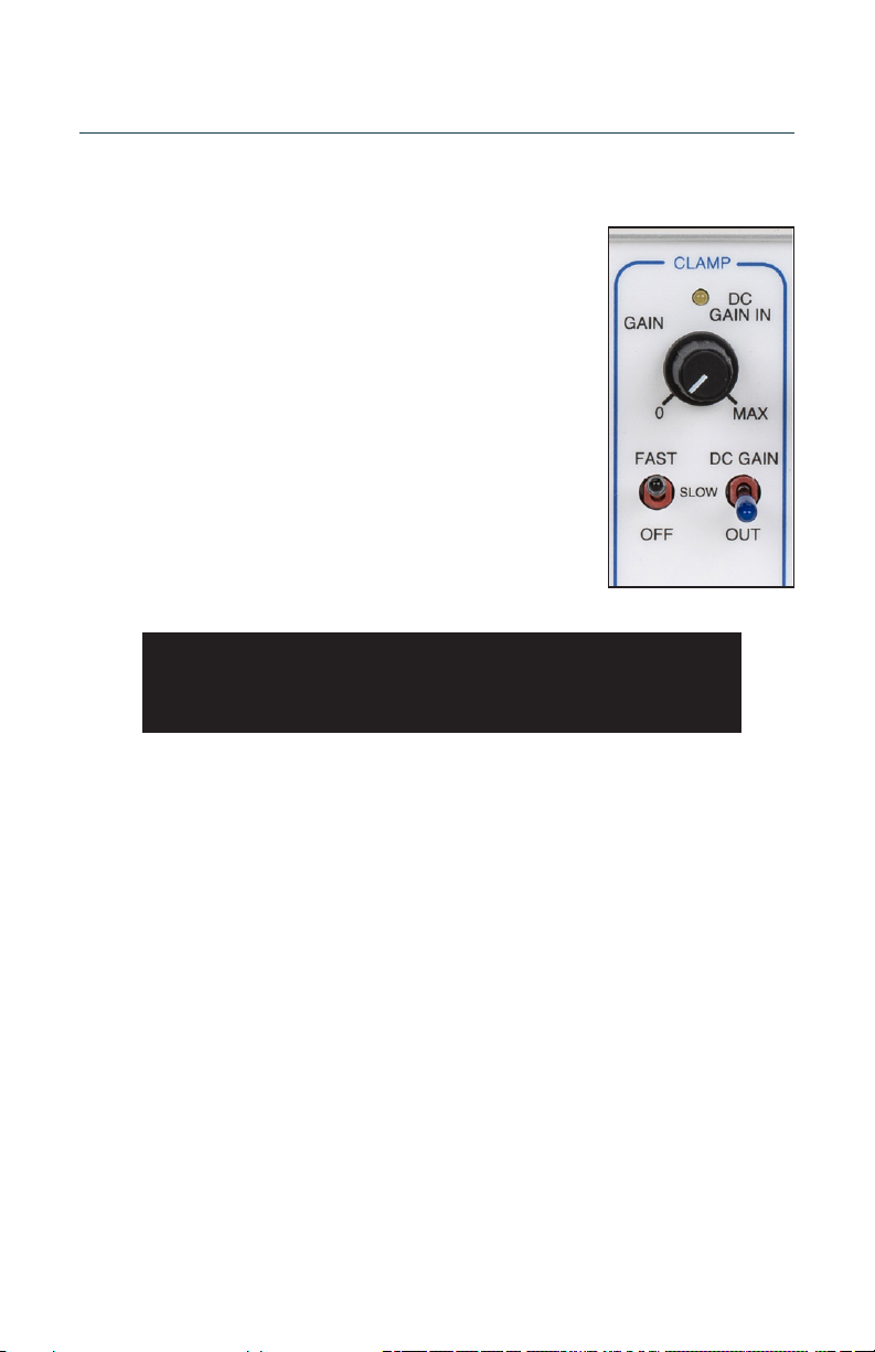
Clamp Secon
SELECTOR switch as well as the GAIN and DC GAIN controls.
o
SLOW
FAST
oocytes.
NOTE: All CLAMP controls are disabled by turning the CLAMP
MODE SELECTOR switch to the o posion. Be sure to switch this
control to the o posion before handling electrodes!

12
Control Description
Commands
The controls and
÷10 input BNC.
x10 or x20
associated toggle switch. A GREEN LED will light whenever the
is on.
Current Electrode
The e
e
contains the indicator and a DIN connector
Ve
ex10
output BNC or on the
Ω] will be displayed on the meter by depressing the
switch is in the off
Vem
will light. An alarm will also sound when the rear panel switch is in
the on
switch is off. A Ve x10 output is also available at the rear panel.

13
www.warneronline.com
Control Description
Rear Panel
ALARM switch and instrument GROUNDS..
NOTE: Verify that the instrument is wired for the proper voltage
before connecng the line cord.
appendix.
FILTER TELEGRAPH output 0.2 to 1.8 VDC in 0.2 V steps.
alarm.
CHASSIS is common with the instrument enclosure and connected to earth through the
NOTE: For safe operaon, the ground pin on the power plug must
not be removed and the use of “cheater” plugs must be avoided.
Addional Components
Voltage Recording Headstages
7250V PROBE
corrosion resistance.
NOTE: The outer shell is electrically driven at the input potenal.
The microelectrode holder mates directly to the 2 mm input pin on the probe body. A
a micromanipulator. The handle can be mounted either axially or perpendicular to the
probe body.

14
Control Description
Bath Headstage
The BATH PROBE is housed in a 2.8 x 3.5 x 4.2 cm
labeled I SENSE and I OUT. The case is electrically
connects to the control unit with a 6 pin connector
Current Electrode Cable
A two meter shielded cable is supplied with a 2
mate with the instrument. The electrode holder has
Model Cell
Comments
Connecng to Line Power
the instrument will be assured provided that the ground circuit in the power outlet is
wired correctly and is connected to earth.

15
www.warneronline.com
Control Description
NOTE: If the ground pin of the power cord is removed for any reason
the instrument chassis must be directly connected to earth ground
High Voltage Outputs
CAUTION!: The current clamp is capable of high power output
(10 mA @ ±180 V) and can cause serious injury if not properly
handled.

16
Using the Model Membrane
resistor shunted by a 0.5 µF capacitor. The voltage and current electrodes are each
resistors.
Inial Instrument Sengs
Control Control block Seng
O
Vm
0.1 V/µA
x1.0
O
Out
CCW
00 mV
x20
O
Ve

17
www.warneronline.com
Using the Model Membrane
Test Procedures
would be within tolerance.
Oset Controls
in the same manner as the Vm OFFSET control. This control is adjustable when the
Voltage Electrode Test

18
Using the Model Membrane
Buzz
Current Electrode Test
DC Clamp Test
METER should read 100 mV and the CURRENT ELECTRODE METER should read 0.00 µA.
19
www.warneronline.com
Using the Model Membrane
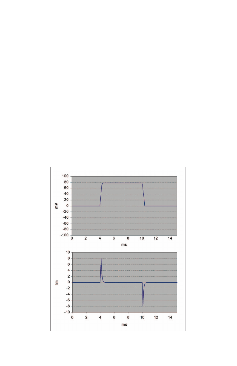
AC Clamp Test
COMMAND IN ÷10 BNC. Monitor the Vm x10 and I MONITOR outputs on the
oscilloscope.
Table of contents
Popular Amplifier manuals by other brands


Radial Engineering
Radial Engineering Headload Prodigy user guide

Dantel
Dantel 00030-20 Installation & operation manual

Marshall Electronics
Marshall Electronics SDI VIDEO DISTRIBUTION AMPLIFIER BD-0314 user manual

Genesis
Genesis Stealth B-200 Brochure & specs

Genz Benz
Genz Benz Shen Pro LT owner's manual

Tecware
Tecware TDA Series Operation manual


