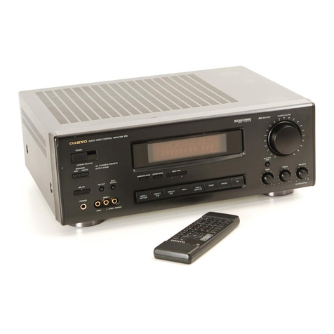
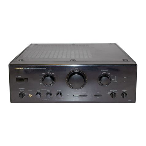
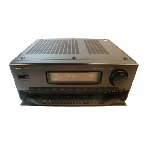
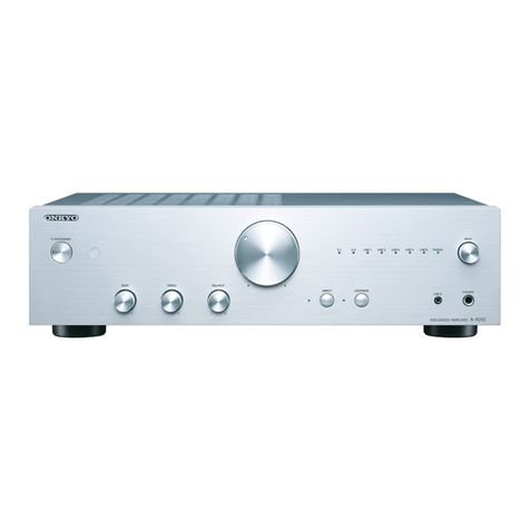
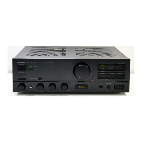
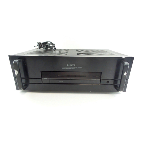
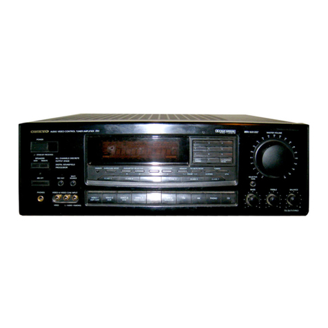
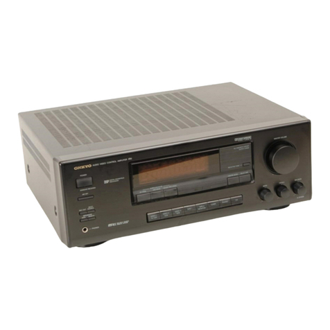
Onkyo TX-903 User manual

TX-903/9071
Quartz
Synthesized
Tuner
Amplifier
-
Instruction
Manual

e
Congratulations
on
your
purchase
of
the
ONKYO
TX-3903,
TX-907
Tuner-Ampilifier.
®
Please
read
this
manual
thoroughly
before
making
connections
and
turning
power
on.
@
Following
the
instructions
in
this
manual
will
enable
you
to
obtain
optimum
performance
and
listening
enjoyment
from
your
new
TX-903,
TX-901.
©
Please
retain
this
manual
for
future
reference.
CONTENTS
FEATU
OS
occ
cece
cece
cree
eee
ce
eee
e
ace
eeeeeaeceeae
cease
eceuaecesaueceaueceeuagecauaeceaececcaeeecsa¢eessessuecesucensseteasecsueecteneerersseeasesauaaeas
EMPOrtaNt
SAFEQUAIAS
2.
eee
cc
cece
cece
ene
ene
n
een
e
eee Ene
Henan
AA
AEGCLEDE
AERC
Ae
eeEAA
GGA
COdEE
Ge
tacccaae
et
ecceteenutasaaeaeeeetseseassaaaeeseeseeas
ad
@
=X
0t-
1904
00)
0
\-
ese
Before
USimg
THiS
Umit...
cece
cece
eee
e
ene
ne
ncn
ee
eee
naa
AEE
EE
AAMAS
GES
EEEAGAAA
SEES
ECEEO
EG
CEessc
Eda
EEEeeeHaee®
seeeeceeaeeeeeeseeeceaeeeeeeeaeees
SYSTEM
COMMECTIONS
222i
c
cece
cneee
eee
eee
c
ene
be
eee
c
sande
cseeAAeAs
Gea
EEAAGHAA
AA
GetAAGEAGc#ec
ceded
esAcecdaabesceeecenaeseceessauseceeuyeeaneeeseetens
Control
POSItiIONS
ANG
NAMES
oo.
cece
cece
keene
ence
ee
bee
ce
bbe
ceeeeeseeeeesueeeeeeesseaaaasaaeaeaaasssasseeessseteteseeereneenes
OPS
ratiONS
ccc
ccc
ccc
eecececccueueeececeuecseeeeueuessauvaveeeecauuusesccuueusecseseueneveesuvavevevecetseavausessesuueecesecersvaeeeessenaeneeeeeteeeaseneess
TrOUDlESHOOTING
QUIde....
cece
cece
e
cece
cence
ne
nek
EEEEEE
AEE
EE
GEG AEE
EEEEDES
EEE;
SE
EE
HEE
DEEDEE;E
Sec
EAL AGG
GAA
GAGA
LESS
EEEAGeAssGaasaabaaaeetEeeeneEe®
Specifications
|...
Seed
beeeueaeseneaneeceeseeseesnsseeeeenaeeccesseeeseuaeeeecscdessssceesenaneeesusnasetseaceeessuuesecsseasesenaeeeaeaneneees
wd
SAO
AWNN
=
—_
Features
eee
eee
Plenty
of
Clean
Power
TX-903:
60
watts
of
continuous
power
per
channel
into
8
ohms
with
no
more
than
0.2%
total
harmonic
distortion
(2
x
100
watts
dynamic
power
at
4
ohms)
TX-901:
45
watts
of
continuous
power
per
channel
into
8
ohms
with
no
more
than
0.3%
total
harmonic
distortion
(2
x
80
watts
dynamic
power
at
4
ohms)
Discrete
Output
Stage
instead
of
the
less
expensive
!C
power
amp
circuitry
used
in
some
receivers,
the
TX-903
and
TX-901
feature
output
stages
composed
of
discrete
components.
Not
just
an
off
—
the
—
shelf
chip,
the
circuit
design
of
the
output
stage
is
optimized
for
the
specific
requirements
of
the
tuner
ampitfier
to
assure
that
the
TX-903
and
TX-901
can
nat
only
deliver
sufficient
power,
but
also
safely
drive
even
low
impedance
loads.
40-Station
FM/AM
Random
Preset
Tuning
Classified
Memory
Preset
The
memory
presets
are
divided
into
six
classes,
A
through
F,
which
can
be
used
for
different
types
of
programs
(rock,
news,
classical,
etc.).
Or
each
member
of
the
family
can
have
a
separate
class
(class
A
for
Dad,
class
B
for
Mom,
class
D
for
Junior).
Any
preset
station
can
be
assigned
to
any
class.
Direct
Access
Tuning
Using
Numeric
Buttons
Instead
of
using
the
UP
or
DOWN
tuning
buttons
to
scan
through
the
available
frequencies
until
the
desired
station
is
located,
Direct
Access
Tuning
lets
you
punch
in
the
broadcast
frequency
directly
using
the
numeric
buttons.
For
example,
103.5
MHz
can
be
selected
by
simply
pressing
the
1,
0,
3
and
5
buttons.
APR
(Automatic
Precision
Reception)
System
Onkyo’s
exclusive
APR
system
lets
every
FM
broadcast
sound
its
best.
Its
buiit
—
in
electronic
brain
monitors
the
signal
and
sefects
the
optimum
settings
for
RF
Local/DX
and
Stereo
Auto/
Mono.
The
APR
system
settings
are
shown
by
indicators
on
the
front
panel.
Six
Program
Inputs
Including
Video
Sound
with
Logic
Controlled
Feather-Touch
Keys
Two
Pairs
of
Speaker
Output
Terminals
Loudness
Control
f21
Compatible
Wireless
Remote
Control
Included
(TX-903
only)
CAUTION
“WARNING”
“TO
REDUCE
THE
RISK
OF
ELECTRIC
SHOCK,
DO
NOT
REMOVE
COVER
(OR
BACK).
NO
USER-SERVICEABLE
PARTS
INSIDE.
REFER
SERVICING
TO
QUALIFIED
SERVICE
PERSONNEL.”
yN
CAUTION
RISK
OF
ELECTRIC
SHOCK
DO
NOT
OPEN
@
The
lightning
flash
with
arrowhead
symbol,
within
an
equilateral
triangle,
is
intended
to
aiert
the
user
to
the
presence
of
uninsulated
“dangerous
voltage”
within
the
product's
enclosure
that
may
be
of
suffi-
cient
magnitude
to
constitute
a
risk
of
electric
shock
to
persons.
@
The
exclamation
point
within
an
equilateral
triangle
is
intended
to
alert
the
user
to
the
presence
of
im-
portant
operating
and
maintenance
(servicing)
tn-
structions
in
the
literature
accompanying
the
appii-
ance.
“TO
REDUCE
THE
RISK
OF
FIRE
OR
ELECTRIC
SHOCK,
DO
NOT
EXPOSE
THIS
APPLIANCE
TO
RAIN
OR
MOISTURE.”
@®
For
models
having
power
cords
with
a
polarized
plug.
CAUTION:
To
PREVENT
ELECTRIC
SHOCK
DO
NOT
USE
THIS
(POLARIZED)
PLUG
WITH
AN
EXTENSION
CORD,
RE-
CEPTACLE
OR
OTHER
OUTLET
UNLESS
THE
BLADES
CAN
BE
FULLY
INSERTED
TO
PREVENT
BLADE
EXPOSURE.
@
Sur
les
modéles
dont
la
fiche
est
polarisée.
ATTENTION:
Pour
PREVENIR
LES
CHOCS
ELECTRIQUES
NE
PAS
UTILISER
CETTE
FICHE
POLARISEE
AVEC
UN
PRO-
LONGATEUR,
UNE
PRISE
DE
COURANT
OU
UNE
AUTRE
SORTIE
DE
COURANT,
SAUF
SI
LES
LAMES
PEUVENT
ETRE
INSEREES
A
FOND
SANS
EN
LAISSER
AUCUNE
PARTIE
A
DECOUVERT.

important
safeguards
es
1
Read
Instructions
—
Ail
the
safety
and
operating
instructions
should
Oe
read
betore
ihe
appilance
is
operated.
Tri
Retain
Instructions
~
The
satety
and
operating
instructions
shouid
be
retained
tor
future
reference.
3
Heed
Warnings
=
Ail
warnings
on
the
appliance
and
in
the
op-
erattng
instructions
should
be
adhered
tu
4.
Follow
tnstructions
=
Ail
operating
and
use
instructions
should
be
tollowed.
5.
Water
and
Moisture
—
The
appliance
should
not
be
used
near
water
-
for
example.
near
a
bathtub,
washbowl,
kitchen
sink,
laundry
tub.
in
é
wet
basement,
or
near
a
swinming
pool,
and
the
like.
6.
Carts
and
Stands
~
The
appliance
shouid
be
used
only
with
a
cart
of
stand
that
is
recoumraended
by
the
manufacturer
6A
An
appliance
and
cart
cambination
PORTABLE
CART
WARNING
should
be
moved
with
care.
Quick
stops,
excessive
tarce,
and
uneven
surfaces
May
Uduse
the
apphance
and
cart
combination
to
overturn.
"
are
sy
Tr.
—_,
/
Wall
or
Ceiling
Mounting
—
The
appliance
should
be
mounted
tu
a
wall
or
ceiling
only
as
recommended
by
the
manufacturer.
4%
Ventilation
©
The
appliance
should
be
situated
so
that
its
location
oF
position
does
nat
intertere
with
its
proper
ventilation.
For
example,
ihe
appliance
should
not
be
situated
on
a
bed,
sofa,
rug.
or
similar
surface
that
may
block
the
ventilation
openings;
or,
placed
in
a
built-in
installation,
such
as
a
bookcase
ur
cabinet
that
may
impede
the
flow
of
aur
through
the
ventilation
openings.
9.
Heat
—
The
appliance
should
be
situated
away
from
heat
sources
such
ds
radiators,
heat
registers.
stoves,
or
other
appliances
(including
amplifiers}
that
produce
heat
+0.
Power
Sources
—
The
appliance
shauld
be
connected
to
a
power
supply
only
of
the
type
described
tn
the
operating
instructions
or
as
marked
on
the
appilance.
11.
Polarization
—
if
the
appliance
ts
provided
a
polarized
plug
having
on
blade
wider
than
the
other.
please
read
the
following
information:
The
polarization
of
the
plug
is
a
safety
feature.
The
polarized
piug
will
only
fit
the
outlet
one
way.
If
the
plug
does
nat
fit
fully
into
the
outlet,
try
reversing
it.
{f
there
ts
stilt
trouble,
the
user
should
seek
the
services
of
a
qualified
electrician.
Under
no
circumstances
should
the
user
at-
tempt
to
defeat
the
polarization
of
the
piug.
12
Power-Cord
Protection
Power-supply
cords
should
be
routed
so
that
they
are
noi
tikeiy
to
be
walked
on
or
pinched
by
ttems
placed
upon
or
against
them.
pay!ng
particular
attention
to
cords
at
plugs,
conventence
receptacles.
and
the
point
where
they
exit
from
the
ap-
phance.
13
Cleaning
—
The
appliance
should
be
cleaned
only
as
recommended
by
the
manufacturer
14.
Power
Lines
-
An
outdovoor
antenna
should
be
located
away
from
power
tines.
15.
Nonuse
Pertods
—
The
power
cord
of
the
appliance
should
be
unplugged
from
the
cutiet
when
left
unused
for
a
tong
period
of
time.
16.
Object
and
Liquid
Entry
-
Care
should
be
taken
so
that
objects
do
not
fal!
and
liquids
are
not
spilled
into
the
enclosure
through
openings
17
Damage
Requiring
Service
—§
The
appliance
should
be
serviced
by
qualified
service
personnel
when.
A.
The
power-supply
cord
or
the
plug
has
been
damaged;
or
B.
Objects
have
fallen,
or
Itquid
has
been
spilled
into
the
appliance:
or
C.
The
appliance
has
been
exposed
to
rain,
or
DO.
The
appliance
does
not
appear
to
operate
normally
or
exhibits
a
marked
change
«n
performance;
or
EF.
The
apphance
has
heen
dropped
or
the
enclosure
damaged.
18.
Servicing
—
The
user
should
not
attempt
to
service
the
appliance
beyond
that
described
tn
the
operating
instructions.
Ail
other
servicing
19.
Outdoor
Antenna
Grounding
©
If
an
outside
antenna
is
con-
nected
to
the
receiver,
be
sure
the
antenna
system
is
grounded
so
as
to
provide
some
protection
against
voltage
surges
and
built
up
static
charges.
Article
810
of
the
National
Electrical
Code,
ANSI/NFPA
70.
provides
information
with
regard
to
proper
grounding
of
the
mast
and
supporting
structure,
grounding
of
the
lead-in
wire
to
an
antenna
discharge
unit,
size
of
grounding
conductors,
location
of
the
antenna-
discharge
unit,
connection
to
grounding
electrodes,
and
requirements
for
the
grounding
electrode,
See
Figure
73.1.
FIGURE
73.1:
EXAMPLE
OF
ANTENNA
GROUNDING
AS
PER
NA-
TIONAL
ELECTRICAL
CODE
ANTENNA
LEAD
IN
__
WIRE
GROUND
CLAMP
we
“a
ae
ANTENNA
DISCHARGE
UNIT
(NEC
SECTION
810-20)
ELECTRIC
SERVICE
FOQUIPMENT
-
ae
GROUNDING
CONDUCTORS
oo
(NEC
SECTION
810-21)
~
GROUND
CLAMPS
POWER
SERVICE
GROUNDING
ELECTRODE
SYSTEM
(NEC
ART
250.
PART
H)
NEC
—
NATIONAL
ELECTRICAL
CODE
$2898A4
Precautions
1.
Warranty
Card
The
serial
number
is
written
on
the
rear
panel
of
this
unit.
Copy
the
serial
number
and
model
number
onto
your
warranty
card
and
keep
it
in
a
safe
place.
2.
Recording
Copyright
Recording
of
copyrighted
material
for
other
than
personal
use
is
illegal
without
permission
of
the
copyright
holder.
3.
AC
Fuse
The
fuse
is
located
inside
the
chassis
and
is
not
user
serviceable.
if
power
does
not
come
on,
contact
your
Onkyo
service
center.
4.
Care
From
time
to
time
you
should
wipe
off
the
front
and
rear
panels
and
the
cabinet
with
a
soft
cloth.
For
heavier
dirt,
dampen
a
soft
cloth
in
a
weak
solution
of
mild
detergent
and
water
or
a
mild
ammonia
cleaner,
wring
it
out
dry,
and
wipe
off
the
dirt.
Fol-
lowing
this,
dry
immediately
with
a
clean
cloth.
Do
not
use
rough
maternal,
thinners,
alcohol
or
other
chemical
soivents
or
cloths
since
these
could
damage
the
finish
or
remove
the
panel
lettering.
Memory
Preservation
This
unit
does
not
require
memory
preservation
batteries.
A
built-in
memory
power
back-up
system
preserves
the
contents
of
the
memory
during
power
failures
and
even
when
the
unit
is
unplugged.
The
unit
must
be
plugged
in
and
the
power
switch
turned
on
and
off
once
in
order
to
charge
the
back-up
system.
Note
that
since
this
is
not
a
permanent
memory,
the
power
switch
must
be
turned
on
and
off
a
few
times
each
month
to
keep
the
back-up
system
operative.
The
memory
preservation
period
after
power
has
been
turned
off
varies
depending
on
climate
and
placement
of
the
unit.
On
the
average,
memory
contents
are
protected
over
a
period
of
a
few
weeks
after
the
last
time
power
has
been
turned
off.
This
period
is
shorter
when
the
unit
is
exposed
to
a
highly
humid
climate.

Before
using
this
unit
1.
Supplied
Accessories
—
—~
TX-903
only
AM
loop
T-shaped
FM
FRI
remote
control
cable
x
1
Remote
contro!
transmitter
x
1
antenna
x
1
antenna
X
1
Battery
x
2
Use
of
Batteries
@
The
remote
control
transmitter
is
powered
by
two
batteries.
Before
using
this
unit
for
the
first
time.
tnsert
the
two
batteries
(included)
as
shown
in
the
diagram.
@
Average
battery
life
is
about
one
year.
This
period
may
be
shorter
depending
on
the
frequency
of
use
and
environment
(temper-
ature
and
humidity)
in
which
the
remote
contro!
transmitter
«s
used.
®
If
the
remote
control
transmitter
does
not
operate
even
though
front
panel
controls
function
normaily,
the
batteries
should
be
replaced.
Use
only
battertes
listed
in
the
following
chart.
Type
Voltage
nese
4)
Push
the
battery
cover
on
the
rear
of
the
transmitter
in
the
di-
.
Do
not
leave
an
expired
battery
in
the
case
as
it
may
leak
rection
of
the
arrow
and
lift
!t
up.
or
damage
the
battery
case.
(2)
Load
the
two
batteries
that
came
with
the
transmitter
or
two
.
When
inserting
the
batteries,
be
sure
the
(+)
and
(—)
ends
battertes
listed
in
the
table.
Load
them
with
the
+
and
—
ends
are
properly
aligned.
facing
as
shown
in
the
diagram.
.
Do
not
use
nickel-cadmium
(rechargeable)
batteries.
(3)
Put
the
battery
cover
back
in
place.
.
Do
not
use
one
specified
(manganese)
battery
and
one
al-
kaline
battery
at
the
same
time.
Replace
both
batteries
at
once;
do
not
use
one
old
and
one
new
battery
together.

System
connections
|
Do
not
plug
in
the
cord
until
all
connections
have
been
made.
General
Switch
the
main
power
switch
off
before
performing
connections.
Also
be
sure
to
perform
left
and
right
channel!
connections
properly.
Indoor
T-Shaped
FM
antenna
or
300
ohm
Outdoor
AM
antenna
FM
Outdoor
Antenna
:
d
75
ohm
coaxial
cable
(3C-2V,
5C-2V)
AM
LOOP
ANTENNA
Connect
only
one
FM
antenna
at
one
time.
TX-903
only
fl
REMOTE
OB
TaOL
ispetign
]
an
Fi
Fe
GN
Ground
connection
is
not
necessary
for
turntable
without
ground
lead
C
(@)
COICD
Se
;
o
TURNTABLE
COMPACT
CASSETTE
TAPE
DISC
DECK
1
PLAYER
or
VIDEO
CASSETTE
RECORDER
FM
Antenna
Connections
Use
the
T-shaped
antenna
if
you
live
in
an
area
where
signal
strength
of
FM
broadcasts
Is
high.
Connect
the
antenna
to
the
FM
300
ohms
terminals
and
place
the
antenna
on
a
wall
or
other
surface
in
the
position
in
which
reception
is
best.
If
signal
strength
is
low
in
your
area,
use
a
multi-element
FM
outdoor
antenna
and
connect
to
this
unit
using
a
75
ohm
coaxial
cable
because
this
type
of
cable
is
more
resistant
to
interference
than
300
ohm
cable.
Consult
your
Onkyo
authorized
service
center
about
the
right
type
of
antenna
for
your
area.
NOTES:
1.
Do
not
connect
both
the
indoor
T-shaped
antenna
and
an
outdoor
FM
antenna.
If
you
decide
to
install
an
cutdoor
antenna,
be
sure
to
disconnect
the
indoor
T-shaped
antenna.
Do
not
use
the
same
antenna
for
both
FM
and
TV
reception
since
the
FM
and
TV
signals
can
interfere
with
each
other.
if
you
must
use
a
common
FM/TV
antenna,
use
a
directional!
linkage
type
splitter.
Note
to
CATV
system
installer:
This
reminder
is
provided
to
call
the
CATV
system
installer’s
at-
tention
to
Article
820-40
of
the
NEC.
which
provides
guidelines
for
proper
grounding
and,
in
particular,
specifies
that
the
cable
ground
shall
be
connected
to
the
grounding
system
of
the
building,
as
close
to
the
point
of
cable
entry
as
practical.
SPEAKER
(A)
cS
Twist
Press
down
the
lever
and
insert
the
wire.
When
the
wire
has
been
inserted
firmly
into
the
hole,
return
the
lever
to
tts
ort-
ginal
position
TX-903
only
Do
—
T
(i...
ac
POWER
Se
SUPPLY
CORD
SPEAKER
IMPEDANCE
4
or
B:
4
ohms
MIN/SPEAKER
A+
B
8
ohms
MIN/SPEAKER
CASSETTE
TAPE
DECK
2
or
GRAPHIC
EQUALIZER
SPEAKER
(B)
Directional
linkage
type
splitter
To
receiver
To
TV
(or
VCR)

AM
Antenna
Connections
An
AM
loop
antenna
is
included
in
the
installation
instructions
bag.
Take
out
the
connection
Jine
and
connect
it
to
the
AM
antenna
terminals.
This
loop
antenna
can
be
placed
on
top
of
any
stable
surface
or
attached
to
a
wall.
Try
several
positions
to
determine
which
gives
the
best
reception.
Be
sure
the
antenna
is
not
near
a
speaker,
power
cord,
television
set,
VCR,
or
motorized
appliances.
When
using
an
external
AM
antenna,
do
not
remove
the
ioop
an-
tenna;
connect
both
antennas
to
the
AM
antenna
terminals.
NOTE:
AM
reception
is
easily
affected
by
television
sets
and
VCRs.
Therefore,
AM
reception
may
be
poor
if
this
unit
is
placed
too
close
to
a
TV
or
a
VCR.
AM
loop
antenna
assembly
Connect
to
the
AM
antenna
terminals.
©)
i
Remove
the
vinyl
tie
and
take
out
the
connection
Bend
in
the
reverse
line.
.
.
direction
@)
a.
With
the
antenna
on
top
of
any
stable
surface
b.
With
the
antenna
attached
to
a
wall
Installation
hole
Mount
on
a
wail,
etc.
Turntable
Connections
(PHONO)
Connect
the
output
leads
of
the
turntable
to
the
PHONO
jacks.
Be
sure
to
connect
the
ground
(earth)
lead
wire
from
the
turntable
to
the
ground
terminal
(GND).
Lack
of
proper
ground
connection
will
cause
hum.
Turntables
not
provided
with
GND
wires
do
not
need
to
be
connected.
1.
Place
the
turntable
on
a
firm
shelf
or
deck
free
from
vibrations
(especially
those
generated
by
the
speaker
system).
If
the
turntable
is
permitted
to
pick
up
such
unwanted
vibrations,
not
only
with
the
performance
of
the
unit
drop,
but
distortion
in
the
bass
frequencies
and
howling
in
the
speakers
may
also
occur.
Check
the
turntable
instruction
manual
for
any
other
precautions.
3.
The
loud
noises
that
occur
when
connecting
and
disconnecting
the
turntable
leads,
replacing
the
cartridge
or
lowering
the
tonearm
could
damage
the
speakers.
Always
turn
the
power
switch
off
before
making
connections.
N
Compact
Disc
Player
or
Other
Component
Connections
(CD)
Connect
the
output
leads
of
the
CD
player
or
an
additional
audio
component
to
the
CD
jacks.
An
Onkyo
CD
player
with
remote
control
that
has
the
(RI
mark
can
be
operated
by
the
TX-903.
(Please
refer
to
“Connections
for
Remote
Contro!”
on
page
6.)
For
more
details,
refer
to
your
CD
player
instruction
manual.
Tape
Deck
and
Graphic
Equalizer
Connections
(TAPE-1,
TAPE-2)
1.
This
unit
has
facilities
for
two
tape
decks.
If
you
are
using
only
one
tape
deck,
connect
it
to
the
TAPE-1/V!IDEO
jacks.
If
you
have
two
tape
decks,
connect
one
to
the
TAPE-1/VIDEO
jacks
and
the
other
to
the
TAPE-2
jacks.
2.
Connect
the
output
leads
of
the
tape
decks
to
the
TAPE-1/ViIDEO
and
TAPE-2
“PLAY”
jacks.
Connect
the
input
leads
of
the
tape
decks
to
the
TAPE-1/VIDEO
and
TAPE-2
“REC”
jacks
of
the
unit.
For
more
details,
refer
to
your
tape
deck
instruction
manual.
3.
To
connect
a
graphic
equalizer,
too,
use
the
TAPE-2
jacks
and
connect
the
second
tape
deck
to
the
tape
jacks
of
the
equalizer.
(See
the
figure)
To
connect
a
graphic
equalizer
and
second
tape
deck
to
the
TAPE-2
jacks.
To
TAPE-2
“REC”
jacks
of
TX-903/901
To
TAPE-2
“PLAY”
jacks
of
TX-903/901
Graphic
equalizer
Second
tape
deck
4.
For
the
audio
signal
of
a
VDP,
VCR,
etc.,
make
the
connections
to
the
TAPE-1/VIDEO
“PLAY”,
“REC”
jacks.
For
details,
refer
to
the
operating
instructions
of
the
video
equipment
concerned.
5.
If
you
have
an
Onkyo
tape
deck
with
the
FRI
remote
control
jack,
connect
it
to
the
TAPE-1/VIDEO
jacks.
Please
refer
to
the
section
“Connections
for
Remote
Control”
on
6
page
regarding
connection
of
the
remote
contro!
cable.
(TX-903
only)
Speaker
Connections
(SPEAKERS)
1.
Connect
the
speakers
to
A
and/or
8
terminals.
2.
When
connecting
speakers,
proper
polarity
is
important.
Always
connect
the
(+)
terminal
(red)
on
this
equipment
to
the
(+)
terminal
on
the
speaker
and
the
{-—)
terminal
(black)
on
this
equipment
to
the
(—)
terminal
on
the
speaker.
3.
Do
not
connect
a
single
speaker
in
paratlel
to
the
right
and
left
channel
outputs.
4.
Use
speaker
cables
that
have
a
low
impedance
and
that
are
as
short
as
possible.
«
Attach
speaker
cables
to
the
rear
panei
speaker
terminals
with
care,
being
sure
that
connections
are
made
firmly
and
that
there
is
no
possibility
of
a
short
circult
occurring.
AC
Outlets
@®
SWITCHED:
(TX-903
only)
These
outlets
are
switched
on
and
off
by
the
Power
button
on
the
front
panel
and
remote
control
transmitter.
Capacity
is
total
100
watts.

(TX-903
only)
Connections
for
Remote
Control
(REMOTE
CONTROL)
@
A
cassette
tape
deck
and
compact
disc
player
that
have
the
Onkyo
FRI
mark
can
be
operated,
using
the
accessory
remote
control
transmitter
with
the
TX-903.
COMPACT
DISC
PLAYER
fal
REMOTE
CONTROL
CASSETTE
>)
TAPE
DECK
A
FRI
Remote
CONTROL
©
An
FRI
remote
control
cable
equipped
with
a
1/8"
(3.5mm)
diameter
miniatura
two-conductor
phone
ptug
is
attached
to
the
TX-903
and
to
any
compact
disc
player,
with
the
FE
mark.
To
use
an
Onkyo
compact
disc
player
and
cassette
tape
deck
with
the
EI
mark,
insert
the
accessory
remote
control
cable
plug
into
the
REMOTE
CONTROL
jacks.
As
far
as
connecting
sequence
is
concerned,
it
doesn't
matter
whether
the
cable
is
connected
from
the
TX-903
to
the
cassette
tape
deck
or
to
the
compact
disc
player.
The
remote
control
transmitter
is
operated
by
facing
it
towards
the
remote
contro!
sensor
of
the
TX-903.
NOTE:
Remote
control
operation
is
not
possible
when
only
the
remote
controi
cable
is
connected.
Remote
control
cable
and
pin
cord
must
be
connected.
Ohta
Direct
function
feature
NOTE:
This
function
works
when
an
Onkyo
cassette
tape
deck
or
CD
player
with
the
FRI
mark
is
connected
to
a
TX-903
with
an
fR1
remote
control
cable.
Just
by
directly
operating
the
desired
component
(compact
disc
player,
or
tape
deck),
the
TX-903’s
input
selector
automatically
switches
to
that
component.
The
component
that
was
being
used
stops,
and
the
desired
component
starts
operation.
Therefore,
it
is
not
necessary
to
switch
the
TX-903’s
input
selector
when
changing
ltstening
sources.
Example
‘When
the
compact
disc
player's
play
button
is
pressed,
the
TX-903's
input
selector
will
switch
automatically
to
“CD.”
If
the
current
listening
source
was
a
tape
deck,
tape
playback
will
stop
and
the
compact
disc
player
will
start
playing.

Control
positions
and
names
NOTE:
eee
ee
@
The
features,
specifications,
and
display
for
the
TX-903
and
TX-901
are
slightly
different.
Read
this
manual
carefully
to
operate
the
mode!
you
have
purchased
correctly.
.
e
information
about
buttons
or
controls,
turn
to
the
page
number
listed
inthe
[
=].
Tuning
Selector
Buttons
(
«€
DOWN,
UP
Pp
}[10]
FM
Muting/Mode
Button
(MUTE/MODE)
[10]
Speaker
Selector
Switches
(SPEAKERS)
(9]
Number
Buttons
(1~9,
0)[10]
Stand-By
Indicator
(TX-903
only)
Loudness
Control
Switch
When
this
indicator
is
lit,
the
power
(LOUDNESS)([9]
can
be
turned
on
by
the
remote
control
transmitter.
Volume
Control
Knob
VOLUME)[9
Headphone
Jack
Remote
Control
Sensor
[8]
(vO
){9]
(PHONES)
(9]
(TX-903
only)
Display
MAIN
POWER
Switch
[9]
Memory
Button
(MEMORY){11]
Balance
Control
Knob
(BALANCE)
[9]
SYSTEM
POWER
Button
Classified
Memory
Buttons
(TX-903
only)
[9]
(CLASS
A
~
CLASS
F)
[11]
Treble
Control
Knob
(TREBLE)
[9]
Direct
Tuning
Button
(DIRECT
TUNING)
[10]
Bass
Contro!
Knob
(BASS)
[9]
Input
Selector
Buttons
(TAPE-2
MONITOR,
TAPE-1/VIDEO,
AM,
FM,
PHONO,
CD)
[9]
FM
Stereo
Indicator
Tape-2
Monitor
Indicator
Tuned
Indicators
Memory
Indicator
4.
FM
Muting
On/Off
indicator
Sleep
Indicator
APA
FM
MUTE
TUNED
MEMORY
SLEEP
RF
STEREO
THU
AUDIO
MUTE
Audio
Muting
Indicator
(TX-903
only)
MODE
MODE
APR
system
indicators
Input
Selector/Frequency
Display
Preset
Station
Classified
Memory
Display

Power
Button
(POWER)
Input
Selector
Buttons
(TAPE-1,
TUNER,
PHONO.
CD,
TAPE-2)
[9]
*
When
the
TUNER
button
is
pressed,
the
station
which
was
received
previously
is
recalled.
Selection
of
AM
or
FM
should
be
done
on
the
main
unit.
CD
Operation
Buttons
(CD)
These
buttons
are
used
to
operate
an
ONKYO
CD
player
with
the
(QI
mark.
>
:
Press
this
button
to
play
the
CD
player.
Tt
:
Press
this
button
to
pause
the
CD
play
back.
To
resume
disc
play,
press
the
PLAY
button.
DISC:
Press
to
use
for
sequential
selection
of
discs
in
the
order
they
were
loaded
on
the
CD
changer.
mM
:Press
this
button
to
stop
the
CD
player.
Kea
=:
Press
this
button
to
go
back
to
the
beginning
of
the
current
track
and
again
to
skip
back
to
the
previous
track.
pp;
=
Press
this
button
to
skip
to
the
next
track.
Audio
Muting
Button
(AUDIO
MUTE)
and
Indicator
This
button
temporarily
switches
off
the
sound
from
the
speaker
or
headphone.
Pressing
this
button
will
operate
the
TX-903
audio
muting
circuit.
The
audio
muting
indicator
“AUDIO
MUTE”
will
flash.
Pressing
the
button
again
or
using
the
POWER
button
on
the
remote
control
transmitter
to
turn
the
power
on
will
turn
off
the
audio
muting.
Sleep
button
(SLEEP)
(Remote
control
transmitter
only)
Press
to
set
the
power
off
timer.
The
sleep
timer
is
a
function
which
button
off
the
power
to
the
system
from
the
time
it
is
set.
When
this
button
ts
pressed,
“90
MIN"
is
displayed
for
5
seconds,
and
the
power
goes
off
90
minutes
later.
Each
time
the
button
is
pressed
during
5
seconds,
the
timer
setting
changes,
by
10
minute
intervals,
suchas
80,
70,
60
....
Whife
the
sleep
timer
is
operating,
the[SLEEP]
indicator
is
lighted.
If
the
sleep
button
is
pressed
during
this
time,
the
amount
of
time
remaining
on
the
sleep
timer
is
displayed,
and
if
the
button
Is
pressed
during
that
display,
10
minutes
will
be
subtracted
from
that
time.
Hf
the
button
is
pressed
when
the
pane!
display
shows
10
minutes
or
less,
the
sieep
timer
is
cancelled,
and
the
power
is
not
turned
off.
Tape
Operation
Buttons
(DECK-A,
DECK-B)
These
buttons
control
Onkyo
double
cassette
tape
decks
that
can
be
remote
controlled.
Use
the
DECK-B
buttons
to
control
single
cassette
tape
decks
with
the
FRE
mark.
@/u
:
When
this
is
pressed,
the
recording
stand-by
mode
is
entered.
4
:
The
tape
plays,
moving
from
right
to
left,
or,
in
the
recording
stand-by
mode,
recording
begins.
‘Interrupts
all
operations.
:
The
tape
plays,
moving
from
left
to
right,
or,
in
the
recording
stand-by
mode,
recording
begins.
.
Fast
forward
from
right
to
left.
-
Fast
forward
from
left
to
right.
ti
no
UUL
riblolD
OD
U
UU
U
_.
|
UUL
UL
¥
i
U
U
Tuner
Operation
Buttons
(TUNER)
[11]
CLASS:
Ciass
selector
button
@
PRESET
P
:
Preset
memory
DOWN/UP
buttons
Volume
Buttons
(UP,
DOWN)
Using
the
remote
controj
transmitter
1.
Remove
the
batteries
if
the
remote
control
transmitter
is
not
going
to
be
used
for
a
jong
time.
2.
The
batteries
of
the
remote
control
transmitter
must
be
repiaced
periodically.
3.
This
unit
uses
infrared
rays.
Therefore,
commands
may
not
be
received
properly
if
the
front
panel
of
this
unit
is
exposed
to
bright
light.
To
prevent
this
from
occurring,
place
this
untt
so
that
it
is
not
directly
exposed
to
bright
light.
4.
If
this
unit
is
placed
inside
an
audio
rack
behind
a
glass
door,
the
door
should
not
have
colored
glass
or
have
any
decorations
on
it,
since
this
could
shorten
the
range
or
prevent
commands
from
being
received.
5.
Use
of
other
infrared
remote
controi
devices
in
the
same
room
may
cause
interference.
6.
The
transmitter
operates
up
to
a
distance
of
about
five
meters
(16
feet).
The
transmitting
window
must
always
be
pointed
at
the
reception
window
when
a
command
is
sent
to
the
TX-903.
7.
lf
this
remote
control
transmitter
does
not
operate
properly,
Remote
sensor
approx.
5m
(16
feet)
/
Remote
contro}
transmitter
confirm
that
the
batteries
are
not
dead.
If
the
problem
persists,
contact
your
Onkyo
Service
Center.

Operations
(3)
SPEAKERS
and
HEADPHONES
(6)
VOLUME
4
OOO
|
©
©
O
Lo
}
(1)
MAIN
POWER
(7)
Tone
Controls
(4)
Input
Selector
Buttons
(2)
SYSTEM
POWER
(5)
Starting
Source
Selected
at
(4)
(TX-903
only)
qd)
Press
the
POWER
switch
to
turn
on
the
power.
Press
this
switch
@)
@)
to
switch
the
on/off
status
of
the
power
supply.
Press
this
button
to
turn
on
power
and
the
AC
outlets
on
the
rear
pane!
when
the
unit
is
in
the
standby
mode.
Power
can
also
be
turned
on
by
using
the
remote
control
power
button
(TX-903
only)
Select
the
desired
pair
of
speakers
by
depressing
the
corre-
sponding
speaker
selector
switch.
®
This
unit
can
drive
two
pairs
of
speakers
in
pairs
{A
or
B)
or
fours
(A
+
B).
To
listen
to
both
speaker
systems
at
once,
depress
both
speaker
selector
switches.
®
Stereo
headphones
with
a
standard
binaural
p!ug
can
be
connected
here.
Press
one
of
the
desired
Input
Selector
Button
(CD,
PHONO,
FM,
AM,
TAPE-1/VIDEQO).
Make
sure
that
the
connections
between
the
input
sources
are
correct.
@®
The
button
pressed
is
shown
in
Display.
For
FM
or
AM,
the
band
and
the
frequency
are
shown
in
Display.
®
Confirm
that
the
TAPE-2
MONITOR
indicator
is
off
when
a
source
other
than
the
TAPE-
2
MONITOR
has
been
selected.
Also
check
the
audio
muting
is
off.
(TX-903
only)
6)
Start
play
of
the
selected
input
source.
@
Follow
the
operating
Instructions
of
that
unit.
@
|tf
FM
or
AM
is
selected,
please
refer
to
the
section
“Tuner
Reception’.
(6)
Adjust
the
Volume
Control
knob
to
the
appropriate
level.
®
Turn
clockwise
to
increase
the
volume
level.
The
volume
can
be
adjusted
manually
and
by
the
remote
control
transmitter’'s
Volume
UP/DOWN
button.
(TX-903
only)
(7)
Adjust
the
Tone
Controls
to
obtain
the
desired
tone
setting.
@
Bass
Control
Knob
(BASS)
Adjust
to
strengthen
or
weaken
bass
response.
@
Treble
Control
Knob
(TREBLE)
Adjust
to
strengthen
or
weaken
treble
response.
@
Balance
Control
Knob
(BALANCE)
Use
this
control
to
adjust
the
relative
volume
levels
of
the
left
and
right
speaker
systems.
@
Loudness
Control
Switch
(LOUDNESS)
When
listening
at
low
volume
levels,
depress
this
switch
to
boost
the
very
high
and
very
tow
frequencies
to
provide
a
more
natural
sound.

Tuner
Reception
Press
the
FM
or
AM
input
Selector
button
and
make
sure
that
the
TAPE-2
MONITOR
indicator
is
off
and
audio
muting
is
off.
@
Tuning
with
the
TUNING
buttons
<
DOWN,
UP
»
M
Receiving
a
station
by
inputting
the
frequency
for
the
station
directly
(Direct
Tuning)
If
the
frequency
for
the
desired
station
is
known,
input
the
fre-
quency
number
directly.
(2)
DIRECT
TUNING
(3)
Number
Buttons
@
How
to
use
the
FM
Muting/Mode
Button
(MUTE/MODE)
In
the
Muting
ON
(STEREQ)
setting,
FM
stereo
reception
ts
possible
and
the
muting
circuit
suppresses
interstation
noise
and
weak
FM
stations.
in
the
OFF
(MONO)
setting,
interstation
noise
will
be
heard
and
even
weak
FM
stations
can
be
received.
(Muting/Mode
operation
is
effective
for
only
FM
reception.)
MUTE/MODE
@
The
Stereo
indicator
will
light
up
if
the
broadcast
is
being
received
in
stereo.
The
Stereo
indicator
will
not
light
up
if
the
broadcast
is
monaural
or
too
weak
to
be
received
in
Stereo.
To
tune
tn
an
FM
or
AM
station
not
stored
in
the
memory,
press
one
of
the
Tuning
selector
buttons.
If
you
press
UP,
the
fre-
quency
Is
increased.
Pressing
DOWN
decreases.
Note
that
the
frequency
is
changed
in
200kHz
steps
in
FM
and
10kHz
steps
in
AM
when
the
Tuning
selector
button
is
pressed
in
single
steps.
lf
this
button
is
pressed
continuously
for
more
than
0.5
seconds,
the
auto
tuning
mode
is
entered,
and
frequencies
are
scanned
automatically.
When
a
broadcast
signal
is
received,
scanning
stops
and
that
frequency
ts
displayed.
If
a
different
frequency
is
desired,
press
the
button
once
again.
®
The
Tuned
indicators
icy
will
light
if
the
broadcast
is
being
properly
received.
These
indicators
do
not
light
for
weak
broadcasts.
The
red
“*
7
"
indicator
blinks
during
scanning.
To
receive
a
weak
FM
broadcast,
set
the
MUTE/MODE
button
to
the
OFF
position
and
select
the
frequency
of
the
desired
broadcast
station.
(1)
Press
the
AM
or
FM
button
of
the
Input
selector
buttons.
2)
Press
the
DIRECT
TUNING
button.
@
°*.-"
or
“-"
will
flash
for
16
seconds
in
the
Frequency
Display.
(3)
Input
the
desired
frequency
number
by
using
the
Number
But-
tons
while
the
cursors
are
flashing.
For
instance,
!f
you
wish
to
receive
the
station
of
88.1MHz,
press
the
Number
Buttons,
8,
8
and
1.
@®
For
AM
reception,
inputting
a
number
to
the
10kHz
digit
sets
O
to
the
tkHz
digit
automatically.
@®
If
the
desired
frequency
set
in
this
operation
does
not
exist,
the
frequency
which
is
the
nearest
and
lower
than
the
desired
frequency
will
be
received.
If
the
frequency
set
is
not
in
the
receive
frequency
range,
the
frequency
flashes
for
two
sec-
onds
and
then
the
previous
frequency
will
be
displayed.
@
|Ifawrong
frequency
has
been
set,
press
the
DIRECT
TUNING
button
and
start
again.
Automatic
Precision
Reception
System
(FM
Mode)
APR
system
is
Onkyo’s
unique
computer-controlled
system.
APR
system
automatically
sets
the
RF
stage
gain
(Distance/
Local),
auta
stereo/mono
reception
modes
to
the
proper
settings
for
the
qualily
of
the
broadcast
currently
being
received.
This
indicator
changes
each
time
the
APR
circuit
switches
between
the
LOCAL/DX
or
AUTO/MONO
to
show
the
current
APR
setting.
(APR
system
is
effective
for
only
FM
reception.)
NOTES:
@®
When
MUTE
MODE
button
ts
not
ON,
the
APR
Mode
se-
lection
function
does
not
operate,
and
the
STEREO
MODE
indicator
is
forced
to
“MONO”.
@®
The
“MONO”
indicator
lights
up
for
FM
monaural
reception.
@
The
RF
MODE
will
indicate
LOCAL
when
suffictent
signal
is
received
Se
aL
TS
SSS
RG

(
pot
y
Fun
ct
on.
The
memory
can
be
divided
(classified)
for
different
users
or
pro-
grams
of
stations.
BM
How
to
classify
stations
With
this
model,
six
classes
(CLASS
A
to
F)
are
available
and
stations
can
be
memorized
in
any
class.
A
total
of
40
stations
can
be
memorized
in
classes
from
A
to
F.
Although
the
same
station
can
be
memorized
in
different
classes,
the
memory
number
for
the
station
will
differ
depending
on
the
order
in
which
the
station
is
memorized
in
the
classes.
(2)
MEMORY
(3)
CLASS
A~F
NOTE:
There
are
times
when
frequencies
are
left
in
the
machine's
me-
mory
from
the
final
testing
done
prior
to
shipment.
tf
this
is
the
case
with
your
TX-903/901,
cancel
unnecessary
preset
stations
according
to
“How
to
cancel
memorized
stations”
and
memorize
desired
frequencies.
a)
Tune
in
the
desired
station
(see
section
on
“Tuner
Reception"
}.
(2)
Press
the
MEMORY
button.
@
The
MEMORY
indicator
will
flash
for
8
seconds.
3)
Press
the
desired
Classified
Memory
button
(one
of
buttons
A
to
F).
@®
The
station
ts
memorized
in
the
selected
class
with
the
me-
mory
number
which
is
the
smallest
of
the
unoccupied
numbers
in
the
class.
By
repeating
the
operations
above,
up
to
40
stations
can
be
me-
morized.
If
an
attempt
is
made
to
memorize
41
stations,
“FULL”
will
be
displayed
in
the
Input
Selector/Frequency
Display,
indicating
that
no
more
stations
can
be
memorized.
@
How
to
cancel
memorized
stations
Retrieve
the
class
number
you
want
to
cancel
(see
“How
to
retrieve
memorized
stations”)
and
then
press
the
MUTE/MODE
button
while
holding
down
the
MEMORY
button.
Another
station
can
be
memorized
with
the
memory
number
which
has
been
cancelled.
@
How
to
retrieve
memorized
stations
a)
Press
the
Classifted
Memory
button
for
the
desired
class.
If
remote
control
is
used,
the
class
next
to
the
present
one
is
re-
trieved
when
the
CLASS
button
is
pressed.
(TX-903
only)
@
The
memory
number
(station)
which
was
being
received
before
the
class
is
retrieved
will
be
recetved.
(2)
There
are
several
methods
to
proceed
after
the
above
operations
are
carried
out.
Use
any
of
the
following
methods.
a.
Pressing
the
same
Classified
Memory
button
again
permits
the
next
preset
memory
number
(station)
to
be
received.
b.
input
the
memory
number
you
wish
to
receive
by
using
the
Number
buttons.
®
Ifthe
memory
number
consists
of
2
digits,
input
two
numbers,
immediately
one
after
the
other.
For
instance,
when
inputting
"45",
“15°
will
not
be
registered
if
you
wait
more
than
one
second
before
inputting
“5”,
resulting
in
only
"1"
being
re-
gistered.
lf
a
number
other
than
a
number
from
1
to
40,
or
a
number
which
has
not
been
memorized
is
input,
the
number
flashes
for
2
seconds
and
then
the
number
which
was
displayed
before
will
be
displayed.
®
\f
a
number
between
1
and
4
is
pressed,
the
display
and
station
are
changed
71
second
later.
c.
Whenthe
<«
PRESET
®
button
of
the
remote
controller
is
pressed,
the
memory
number
of
the
class
currently
being
received
will
be
incremented
or
decremented.
Keeping
pressing
the
button
increments
or
decrements
continuously.
After
the
maximum
or
minimum
number
is
reached,
the
next
class
or
one
before
the
present
class
will
be
entered.
(TX-303
only)

T
Oo
900
©
Og
Make
ail
connections
between
the
tape
deck
and
the
unit
as
shown
in
the
System
Connections
Diagram.
Radio:
Press
the
FM
or
AM
Input
Selector
button.
Record:
Press
the
PHONO
Input
Selector
button.
CD:
Press
the
CD
Input
Selector
button.
Put
the
tape
deck
in
the
recording
mode.
The
recording
can
be
monitored
through
the
speakers
or
headphones
as
desired.
For
TAPE-2,
turn
on
the
corresponding
Tape
Monitor
button
to
hear
the
signal
that,
having
been
recorded,
is
returned
from
the
deck
to
the
TX-903/901.
(if
the
deck
has
three
heads}.
Set
the
proper
recording
level
using
the
controls
on
the
tape
deck
used
for
recording.
Also,
during
recording
and
dubbing
operations,
never
change
the
positions
of
any
controls
(bass,
treble,
etc.)
on
this
unit.
Connect
the
two
tape
decks
to
this
unit
as
shown
in
the
System
Connections
diagram.
Load
the
original
tape
in
tape
deck
1
and
the
blank
tape
in
tape
deck
2.
Press
the
TAPE-1
Input
Selector
button.
Put
tape
deck
1
in
the
playback
mode
and
tape
deck
2
in
the
recording
mode.
The
source
signal
can
be
monitored
through
the
speakers
or
headphones,
when
the
TAPE-2
MONITOR
button
is
in
the
OFF
position.
If
tape
deck
2
has
three
heads,
the
just-recorded
signal
can
be
monitored
(when
the
TAPE-2
MONITOR
button
is
in
the
ON
position).
Refer
to
the
tape
deck
instruction
manuals
for
more
details.
9
the
Graphic
Equalizer
onnect
the
graphic
equalizer
to
the
TAPE-2
jacks
on
the
rear
panel.
If
a
second
tape
deck
is
used,
connect
it
to
the
tape
jacks
on
the
graphic
equalizer.
Press
the
TAPE-2
MONITOR
button.
Follow
the
graphic
equalizer
operating
instructions.
To
record
an
equalized
signal,
use
tape
deck
2
(connected
to
the
equalizer)
for
recording.

Trouble
shooting
guide
NOTE
(TX-903
oniy):
If
a
problem
occurs,
first
operate
the
unit
using
the
frant
panel
controls
to
confirm
that
it
is
not
due
to
a
malfunction
(or
worn
a
le
AC
out
batteries)
of
the
remote
control
transmitter.
Cause
@
Power
cord
is
disconnected.
®
Connect
power
cord.
@
AC
fuse
blown.
®
Contact
Onkyo
Service
Center.
®
Tape
monitor
switch
on.
®
Switch
to
off.
®
Audio
muting
switch
on.(TX-903
only)
|
@
Switch
to
off
by
remote
control
transmitter.
@®
Bad
connections.
@
Check
input
ieads,
speaker
leads,
pin
plugs,
etc.
®
Amplifier
protection
circuitry
has
been
|
@
Contact
Onkyo
Service
Center.
activated.
ee
Hum,
low
frequency
noise
®
Poor
or
no
input
ground.
@
Check
outer
conductor
of
input
plugs.
@
Poor
or
no
phono
motor
ground.
@
Check
for
proper
ground
connection.
Howling
when
the
volume
is
turned
up.
|
@
Turntable
and
speakers
are
too
close
®
Move
them
farther
apart.
Power
but
no
sound.
together.
ee
ee
es
Rough
or
scratchy
sound.
High
range
is
|
@
Stylus
of
pick-up
Is
worn.
@
Replace.
not
clear.
®
Stylus
tip
is
dirty.
®
Clean.
@
Treble
control
too
high.
_
_@
Turn
treble
control
down.
AM
stations
cannot
be
received.
®
AM
loop
antenna
is
not
attached.
@
Connect
the
included
AM
loop
antenna
to
the
AM
antenna
terminals.
_
Buzzing
noise
on
AM
(particularly
con-
|
@
Noise
from
electrical
apparatus
such
@
Move
AM
loop
antenna
to
different
position.
spicuous
at
night
or
with
weak
stations).
as
fluorescent
lamp
.
®
Set
up
outdoor
AM
antenna.
__
High
pitched
noise
or
buzzing
noise
on
®
Noise
from
TV.
®
Place
the
AM
loop
antenna
as
far
as
possible
from
the
TV.
@
Move
unit
away
from
FV
set.
AM.
i
a
a
EN
ST
®
Noise
caused
by
turning
fluorescent
lamp
on
and
off.
@
Noise
from
automobile
ignition.
@
Move
antenna
as
far
as
possible
fram
the
flu-
orescent
lamp.
@
install
and
FM
outdoor
antenna
as
far
as
possible
from
the
road.
®@
Change
the
position
or
direction
of
the
outdoor
antenna.
Crackling
noise
on
AM
and
FM.
@
Change
to
T-shaped
antenna.
@
Use
antenna
which
has
better
directivity
and
se-
lect
a
point
where
the
distortion
Is
least.
®@
Station
is
too
strong.
@
Multiple
reflection
of
the
radio
waves
because
of
tall
buildings
or
mountains.
FM
tuned
and
stereo
indicators
light
but
sound
is
distorted
and
stereo
separation
is
bad.
FM
tuned
and
stereo
indicators
flicker
on
and
off
and
hiss
is
heard
on
FM.
@
Install
an
outdoor
FM
antenna.
®
Change
the
position
or
direction
of
the
outdoor
antenna.
®
Station
is
too
weak.
®@
Stereophonic
FM
broadcasts
cover
only
about
half
the
distance
of
monaural
broadcasts.
®@
The
memory
contents
are
lost
if
the
power
switch
is
not
turned
on
a
few
times
each
month.
Store
all
stations
again
and
remember
to
turn
the
power
on
a
few
times
each
month.
®
The
power
switch
has
not
been
turned
on
for
a
long
time
or
the
power
cord
has
been
unplugged
for
a
long
time.
No
station
is
recalled
when
a
preset
sta-
tion
number
ts
input.
®@
No
batteries
in
remote
control
trans-
@®
Insert
batteries.
mitter.
®@
Replace
batteries.
®
Batteries
have
worn
out.
Front
panel
controls
function
but
remote
control
transmitter
does
not.
(TX-903
only)
The
tuning
steps
by
which
the
tuned
frequency
changes
on
each
band
have
been
set
at
the
factory
to
the
proper
value
for
the
country
where
each
unit
is
to
be
sold.
If
you
use
the
unit
in
a
country
where
a
different
tuning
step
is
required
or
if
the
broadcast
frequencies
in
your
country
change
so
that
you
can
not
tune
in
radio
stations
precisely,
contact
your
authorized
Onkyo
Service
Center.

Specifications
AMPLIFIER
SECTION
Power
Output:
Total
Harmonic
Distortion:
IM
Distortion:
Damping
Factor:
Frequency
Response:
RIAA
Deviation:
Sensitivity
and
Impedance:
Phono
Overload:
Signal-to-Noise
Ratio:
Tone
Controls:
Loudness
(—30dB):
Muting:
TUNER
SECTION
FM:
Tuning
Range:
Usable
Sensitivity:
50dB
Quieting
Sensitivity:
Capture
Ratio:
Image
Rejection
Ratio:
IF
Rejection
Ratio:
Signat-to-Noise
Ratio:
Alternate
Channel
Atternuation:
AM
Suppression
Ratio:
Harmonic
Distortion:
Frequency
Response:
Stereo
Separation:
Stereo
Threshold:
AM:
Tuning
Range:
Usable
Sensitivity:
Image
Rejection
Ratio:
IF
Rejection
Ratio:
Signai-to-Noise
Ratio:
Harmonic
Distortion:
GENERAL
Power
Supply:
Dimensions
(W
x
H
x
D):
Weight:
TX-3903
TX-901
60
watts
per
channel,
min.
RMS,
at
8
ohms,
both
45
watts
per
channel,
min.
RMS,
at
8
ohms,
both
channels
driven,
from
40Hz
to
20kHz,
with
no
more
than
0.2%
THD.
0.1%
at
30W
0.1%
at
30W
50
at
8
ohms
20
—
30,000
Hz
+
1dB
20
—
20,000
Hz
+
0.8dB
Phono:
2.5mV/50
kohms
CD/Tape
Play:
150mV/50
kohms
Tape
Rec:
150mV/3.5
kohms
120mV
RMS
at
1kHz,
0.2%
THD
Phono:
80dB
(at
5mV
input,
IHF-A)
CD/Tape:
100dB
(|HF-A)}
Bass:
+
10dB
at
100Hz
Treble:
+
10dB
at
10kHz
+7dB
at
70Hz,
+5dB
at
1OkHZ
—oOO
87.9
—
107.9MHz
(200kHz
steps)
Mono:
12.4dBf,
2.3uV
Stereo:
18.2dBf,
4.5yV
Mono:
18.2dBf,
4.5uV
Stereo:
38.2dBf,
45yV
1.5dB
40dB
90dB
Mono:70dB
=
Stereo:65dB
55dB
50dB
Mono:0.15%
Stereo:0.3%
30
—
15,000Hz
+
1.5dB
40dB
at
1kHz
17.2
dBf,
4yV
530
—
1710kHz
(10kHz
steps)
30pnV
40dB
40dB
40dB
0.8%
AC120V,
60Hz
455
x
120
x
316
mm
17-15/16"
x
4-6/8"
x
12-7/16"
8.0
kg.,
17.6
Ibs.
Remote
control
transmitter
RC-223S
(TX-903
only)
Transmitter:
Signal
range:
Power
supply:
Infrared
Approx.
5
meters
(16ft.
4”)
Two
“AA”
batteries
(1.5V
x
2)
channels
driven,
from
40Hz
to
20kHz,
with
no
more
than
0.3%
THD.
0.1%
at
30W
0.1%
at
3OW
50
at
8
ohms
20
-—
30,000
Hz
+
1dB
20
—
20,000
Hz
+
0.8dB
Phono:
2.5mV/50
kohms
CD/Tape
Play:
150mV/50
kohms
Tape
Rec:
150mV/3.5
kohms
120mV
RMS
at
1kHz,
0.3%
THD
Phono:
80dB
(at
SmV
input,
jHF-A)
CD/Tape:
100dB
(IHF-A)
Bass:
+
10dB
at
100Hz
Treble:
+
10dB
at
10kHz
+7dB
at
70Hz,
+5dB
at
10kHz
87.9
—
107.9MHz
(200kHz
steps)
Mono:
12.4dBf,
2.3nV
Stereo:
18.2dBf,
4.51uV
Mono:
18.2dBf,
4.51V
Stereo:
38.2dBf,
45uV
1.5dB
40dB
90dB
Mono:70dB
Stereo:65dB
55dB
50dB
Mono:0.15%
Stereo:0.3%
30
—
15,000Hz
+
1.5dB
40dB
at
1kHz
17.2dBf,
4uV
530
—
1710kHz
(10kHz
steps)
30nV
40dB
40dB
40dB
0.8%
AC120V,
60Hz
455
x
120
x
316
mm
17-15/16"
x
4-6/8"
=x
12-7/16"
7.2kg.,
15.9
Ibs.
Specifications
and
features
are
subject
to
change
without
notice.

ONKYO
CORPORATION
International
Division:
Onarimon
Yusen
Bidg.,
23-5,
Nishi-Shimbashi
3-chome,
Minato-ku,
TOKYO
105,
JAPAN
Tel:
03-3432-6987
Fax:
03-3436-6979
ONKYO
U.S.A
CORPORATION
200
Williams
Drive,
Ramsey,
N.J.
07446,
U.S.A.
Tel:
201-825-7950
Fax:
201-825-8150
SN
29341684
AY
This manual suits for next models
1
Table of contents
Other Onkyo Amplifier manuals

Onkyo
Onkyo A-9010 User manual

Onkyo
Onkyo M-5160 User manual

Onkyo
Onkyo A-5VL - Integrated Stereo Amplifier User manual

Onkyo
Onkyo AS-V620 User manual

Onkyo
Onkyo TX-850 User manual

Onkyo
Onkyo TX-904 User manual

Onkyo
Onkyo AS-V620 User manual

Onkyo
Onkyo A-809 User manual

Onkyo
Onkyo PA-MCSSOl User manual

Onkyo
Onkyo TX-890 User manual