HARVARD H407 User manual
H407
OWNER’S MANUAL
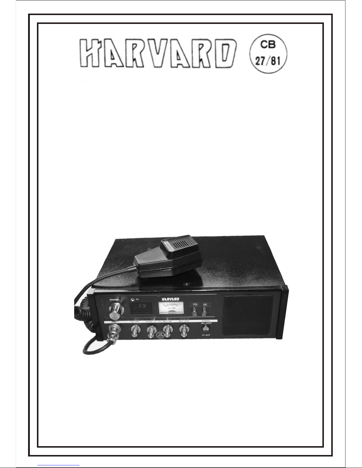
40-Channel FM Base Station
Citizenband
Transceiver
H407

GENERAL DESCRIPTION
The Harvard H407 Is an advanced solid-state 2-way CB radio. It employs the very
latest technology to provide 40 channels of operation by means of digital frequency
synthesis with phase lock loop (PLL) circuitry FM channel on the citizens band
of 27.80125 to 27.99125 MHz.
This transceiver also includes many unique features'which will provide greater
operating convenience and assure optimum communications under a wide range of
conditions.
We strongly suggest you read this operating manual carefully before operation so
that you may receive the full benefit of this transceiver.
PACKING
This unit has been especially protected for shipment. Open the carton carefully to
avoid damage. Examine the unit for any visible damage. If the transceiver has been
damaged In shipment, save the box and packing material and notify the transportation
company.
DESCRIPTION
A. GENERAL
Your new H407 combines features and innovations for all-round versatility. The
H407 will operate from 240 Volts AC (house current) qr 12 Volts DC (positive or
negative ground). The front mounted speaker projects sound forward for better
clarity. A public address circuit allows you to convert the H407 into a paging
system. Jacks are provided for external speakers and PA speakers.
B. RECEIVER
A tuned RF stage is employed to pull in even weak signals. The I.F. system is dual
conversion and a ceramic filter is employed to reduce interference from adjacent
channels. A RF Gain Control is provided to let you adjust the sensitivity level of
the receiver, A Mic Gain Control lets you adjust modulation levels to maximize
performance. A large meter monitors the incoming signal level. Other features
include Volume, Squelch, and Transmit Indicator Light.
C. TRANSMITTER
The heart of your H407 is the all new PLL oscillator. It provides full 40 channel
operation from only one crystal. Integrated circuits plus other components replace
the balance of crystal. PLL is the most accurate frequency system available for CB,
WARNING: TO PREVENT FIRE OR SHOCK HAZARD,
DO NOT EXPOSE THIS APPLIANCE TO RAIN OR MOISTURE.
D. LICENCE
You may not operate this equipment until you have obtained a C.B. Licence,
Details of the licence may be obtained from your local post office.
- 2 -
NOTE: A CB Licence is no longer a requirement for CB Radio use within the UK.
- 3 -

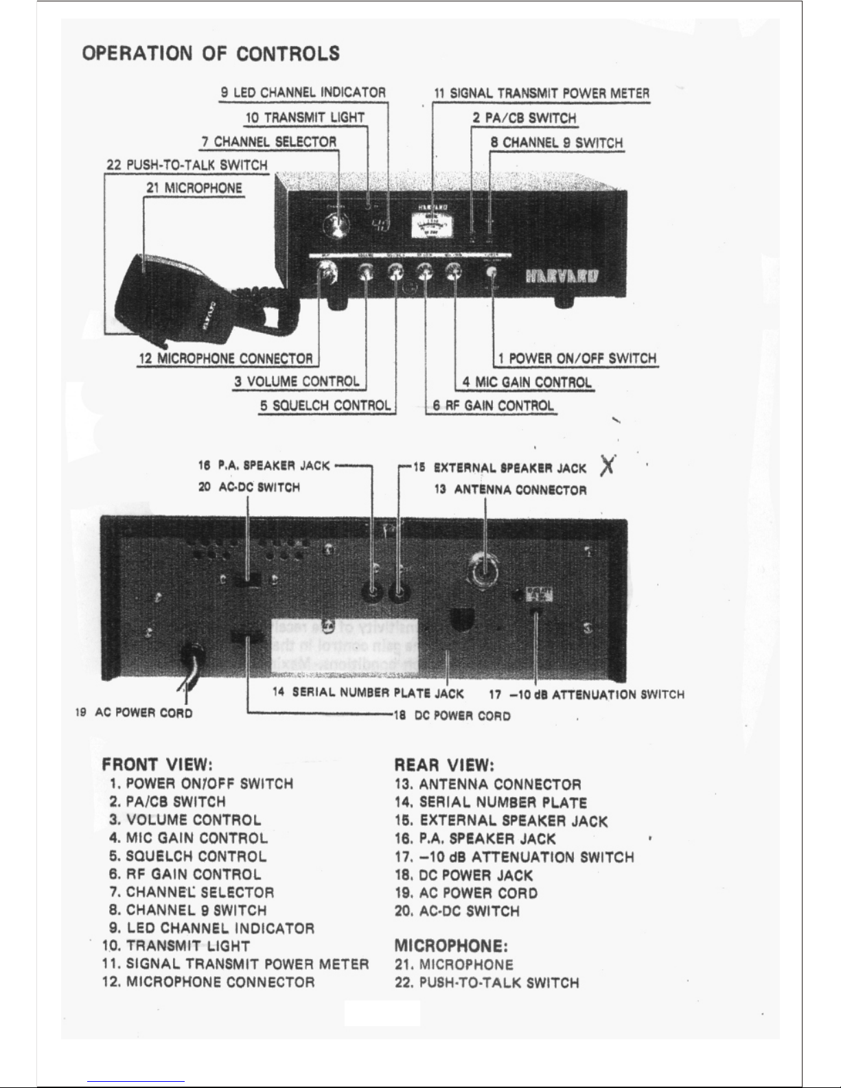
FEATURES AND CONTROLS
POWER ON/OFF SWITCH
The switch simply turns your H407 on and off.
VOLUME CONTROL
This control adjusts the receiver volume. The control should be turned clockwise
to increase the volume,
SQUELCH CONTROL
The Squelch Control Is used to eliminate background noise when there are no signals
present strong enough to overcome the noise. To adjust the Squelch Control, select a
channel where there is no signal. Turn the volume up to normal listening levels. Rotate
the squelch control clockwise until the background noise disappears.
CHANNEL SELECTOR
The channel selector switch is used to select the channel frequency. It automatically
adjusts both the transmitter and receiver frequencies, and displays your selection in
bold L.E.D. (Light Emitting Diodes) numerals.
MIC GAIN CONTROL
This control allows you to adjust microphone sensitivity or power to compensate for
different operating situations. Maximum microphone sensitivity or power is obtained at
the full clockwise position and the control should be set to this point for normal operation
and maximum range. Examples of how this control can help to maximize communications
effectiveness are as follows: When you are operating at extremely close proximity
(within 100 yards or meters) of the other station, reducing the microphone gain may
help to eliminate overload and distortion at the other station. When you are operating in
an extremely noisy environment such as may be found In the cab of certain (ergo trucks,
open sports cars, or around noisy machinery, in order to avoid or reduce the amount of
noise that goes out with your signal, you can reduce the microphone gain and by
speaking more closely and loudly into the microphone, reduce the ratio of noise to voice.
RF GAIN CONTROL
This control allows you to adjust the basic sensitivity of the receiver section of the
transceiver. It is somewhat like the microphone gain control in that it allows you to
compensate for different or varying operation conditions. Maximum RF Gain or receiver
sensitivity is obtained at the maximum clockwise position of this control, and the control
should be set to this point for normal operating and maximum range. For example,
when operating at close proximity to other strong signals, it may be helpful to reduce
the RF Gain to avoid overload or distortion or interference from adjacent channels.
PA-CB SWITCH
When the PA/CB switch is placed in the PA position, it converts your H407 into a
powerful Public Address System. The "PA" function requires an optional 8-16 ohm
paging speaker. This speaker must be connected to the "PA" jack on the back of the set.
Once this speaker has been connected, simply put the PA switch in the "PA" position
and depress the microphone Push-To-Talk switch to activate the set.
S/RF METER
The H407 is equipped with a combination S-RF Meter. In the receive position,
the meter reads the level of the incoming signals. In the transmit position, the meter
indicates relative power output.
- 4 -

- 5 -
CHANNEL 9 PRIORITY SWITCH
When this twitch It pushed, channel 9 will be displayed on LED display and set will
operate only on "Emergency Channel 9". N/B: Channel 9 is the national recognised
"Emergency Channel". Use this channel only in cases of emergency.
TRANSMIT LIGHT
This light gives you a visual indication of the transmit mode.
AC-DC SWITCH
This switch selects the power Input source. Slide to AC for 240 Volts 50 Hz
(house current). Slide to DC for 12 Volts .operation.
PA SPEAKER JACK
For attaching optional 8-16 ohm PA speaker. Use 3.5mm jack.
EXTERNAL SPEAKER JACK
You may add any 8-16 ohm external speaker. Simply plug your accessory speaker
into the jack. Inserting the 3.5mm plug will automatically disconnect the Internal speaker.
May also be used for headphones.
DC POWER CORD
To attach unit to positive or negative ground 12 Volts source, a convenient quick
disconnect is provided.
AC POWER CORD
To operate unit from 240 Volts 60 Hz (ordinary house current).
ANTENNA CONNECTOR
A standard SO-239 type connector Is supplied for attaching either mobile or base antennas.
MICROPHONE
The receiver and transmitter are controlled by the push-to-talk switch on the microphone.
To transmit, simply press in this switch. Release the switch to receive. When transmitting,
hold the microphone three to four inches from your mouth and speak clearly at normal
voice levels.
-10 dB ATTENUATION SWITCH
If your antenna is mounted at a height exceeding 7m, you must push this switch to
release into the out position. This will reduce the transmit power.
NOTE: Use of the “-10 dB ATTENUATION SWITCH” is no longer a requirement
for CB Radio use within the UK.

- 6 -
SPECIFICATIONS
GENERAL
1. Semiconductors
2. Self-Contained Speaker
3. Microphone
4. Controls, Indicators and
Connectors
18 transistors, 2 FET, 28 diodes, 4 integrated
circuits
3 inch, 8 ohms voice coil
Dynamic microphone with push-to-talk switch,
500 ohms
Volume control
Variable Mike Gain Control
Variable Squelch Control
Variable RF Gain Control
Power on-off Push Switch
Channel Selector
LED channel Indicator
TX Light (RED)
Illuminated S/RF power meter
AC-DC Slide Switch
PA-CB Slide Switch
Channel 9 Switch
Coaxial type antenna connector
Microphone connector
DC 12V Jack
External Speaker Jack
Public Address Speaker Jack
13.2 Volts DC (positive or negative ground)
AC 240V 50 Hz
Vinyl Clad Steel
210(D)x29B(W)x90(H)mm
5. Power Supply
6. Cabinet Description
7. Dimensions
RECEIVER
1. Frequency Range (MHz)
2. Sensitivity
3. Selectivity
4. Adj. Channel Rejection
5. Audio Power Output
at 8 ohms at 4 ohms
6. Audio Fidelity
(1 KHz 0 dB, 6 dB down)
7. Squelch Sensitivity
(Threshold)
8. Spurious Rejection
27.60125-27.99125 0
5MV for 20 dB S + N/N
5 KHz minimum at 6 dB down
45 dB nominal at ±10 KHz
More than 2 W at 10% distortion
More than 4 W at 10% distortio
400 Hz-2000 Hz
Less than -10 dB NQ level nominal
(approx.0.15 to 0.2^V)
More than 45 dB

SPECIFICATIONS
TRANSMITTER SECTION
a. RF Output Power
b. Freq. Deviation (@1 KHz)
c. Audio Freq. Response
4 watts (MPT-1320)
±2.5 KHz max.
+2
-5
at 0.3-3.0 Khz pre-emphasise
less than 50nw
dB per 6dB/OCT
d. Spurious Emission
80 - 86 Mhz
87.5 -118 Mhz
135-136 Mhz
174-230 Mhz
470 - 862 Mhz
Other Freq. Less than 0.25uW
e. Adjacent Channel Power less than 10uW
POWER SUPPLY
AC OPERATION
For your own safety read following instruction carefully before attempting to connect
this unit to the mains.
IMPORTANT
The wires in this mains lead are coloured in accordance with the following code:
Green-and-yellow : Earth
Blue : Neutral
Brown : Live
As the colours of the wires in the mains lead of this apparatus may not correspond with
the coloured markings identifying the terminals in your plug proceed as follows:
The wire which is coloured green-and-yellow must be connected to the terminal in the
plug which is marked by the letter E or by the safety earth symbol or coloured green or
green-and-yellow.
The wire which is coloured blue must be connected to the terminal which is marked with
the letter N or coloured black.
The wire which is coloured brown must be connected to the terminal which is marked
with the letter L or coloured red.
If a 13A plug is used, fit a 3A Fuse. If any other plug is used, protect with a 5A fuse in
the plug, adaptor, or at the distribution board.
CAUTION: TO PREVENT ELECTRIC SHOCK DISCONNECT FROM THE MAINS BEFORE
REMOVING COVER. NO USER-SERVICEABLE PARTS INSIDE.
REFER SERVICING TO QUALIFIED SERVICE PERSONNEL
SAFETY PRECAUTION:
THIS EQUIPMENT MUST BE DISCONNECTED FROM THE MAINS WHEN NOT IN USE.
*DO NOT ALLOW THIS UNIT TO BE EXPOSED TO RAIN OR MOISTURE.
WARNING: THIS APPARATUS MUST BE EARTHED.
- 7 -

- 8 -
POWER SUPPLY
DC OPERATION:
While It is highly unlikely that you will use your H407 in an automobile, you may
desire to run it off a 12 Volt battery in case of emergencies. You can do this by
attaching the DC cord to the set. Attach the red (fused) wire to the battery plus (+)
terminal. Attach the black lead to the battery minus (-) terminal.
SHOULD YOU DESIRE TO OPERATE THE H407 IN YOUR VEHICLE. IT IS EQUIPPED TO
OPERATE EITHER POSITIVE OR NEGATIVE GROUND. CAREFULLY FOLLOW THE
INSTRUCTIONS BELOW.
NO MOBILE MOUNTING BRACKET IS SUPPLIED OR AVAILABLE.
NEGATIVE - POSITIVE GROUNDING:
Almost all cars and most trucks currently manufactured are negative ground.
There are some large trucks and construction equipment which operate on
positive ground. Your Harvard H407 will operate on either. In the negative ground
systems, the minus (-) pole of the battery is attached to the car body, engine
block, etc.
NEGATIVE GROUND HOOKUP:
Attach the red (fused) wire to the fuse block terminal or any convenient plus (+)
lead. Devices operated by the Ignition key such as the radio, light etc. are best
since when you turn the ignition off, the unit will be turned off. Attach the black
lead to the car body via any convenient method.
NOTE: Many newer cars use plastic dash pieces. Make sure the screw or contact
you choose is attached to the metal framework of the car.
POSITIVE GROUND HOOKUP:
In the event that you do have a positive ground vehicle, the following hookup
must be made. Attach the red (fused) lead to the car body via any convenient
screw, bolt etc. Attach the black lead to the terminal block or any convenient wire
which goes to the minus (-) pole of the battery.
FAILURE TO MAKE THE PROPER CONNECTION COULD RESULT IN UNIT DAMAGE.
ANTENNA CONNECTION
Before operating the transceiver, you must connect a proper antenna system.
Operating the transceiver without an antenna or a dummy load may cause
damage to the expensive RF power transistors.

- 9 -
ANTENNA REQUIREMENT
This transceiver will operate with any standard 52 ohm ground-plane, vertical, mobile
whip, long wire or other CB antenna. A standard 80-239 type connector is provided on
the back panel for use with popular PL-259 antenna plug.
ANTENNA INSTALLATION
BASE STATION:
When the H-407 is used as a base station, any Citizens Band beam, dipole, ground plane
or vertical antenna may be used. A ground plane type will provide greater coverage and,
since it is essentially non-directional, It is ideal in base station to mobile operation. The
range of the transceiver depends basically on the height of the antenna and, whenever
possible, select the highest location within Home Office limits. (These limits are printed
on the C.B. Licence form).
MOBILE ANTENNAS:
A vertical whip antenna is best suited for mobile use. A non-directional antenna must be
used for best results in any case. The base loaded whip antenna will normally provide
effective communications. For greater range and more reliable operation, a full quarter-
wave whip should be used. Either of these antennas use the metal car body as a ground
plane and the shield of the base lead as well as the metal case of the transceiver should
be grounded. A standard antenna connector (type 80-239) is provided on the transceiver
for easy connection to a standard PL-259 cable termination.
NOTE: The above Home Office Limits no longer apply to CB Radio use within the UK.

- 10 -
MOBILE INSTALLATION
A location in the car or truck should be chosen carefully for convenience of operation
and non-interference with normal driving functions. Mounting may be under the dash
or instrument panel or any place a secure installation can be made, The 12-Volt cable
may be connected to any convenient terminal, but preferably to the ignition switch to
prevent unauthorized persons from operation of your unit. With this method, the unit
will only operate when your key is turned on. Engine ignition interference should not
be a problem, and vehicles equipped with standard broadcast radios will have enough
suppression to eliminate ignition interference. If interference is present, any skilled auto
radio repairman should be able to eliminate it for you.

- 11 -
OPERATING PROCEDURES
A. AC OPERATION
CHECK AND MAKE SURE THE PROPER CONNECTIONS HAVE BEEN MADE ON
THE POWER CABLE, ANTENNA, AND MICROPHONE.
B. RECEIVER
a. Plug in microphone,
b. Turn the volume and squelch controls fully counter clockwise,
c. Turn the RF Gain and the MIC Gain fully clockwise.
d. Set Channel selector to desired channel.
e. Put AC-DC switch to the AC position.
f. Plug AC cord into any convenient house outlet.
g. Place On/Off pushbutton in "On" position and increase volume to desired level.
h. With no signal present, rotate Squelch control clockwise until the rushing noise
disappears.
C. TRANSMITTER
CAUTION: NEVER OPERATE YOUR H407 WITHOUT AN ADEQUATE
ANTENNA SYSTEM OR LOAD. ANTENNA SWR SHOULD
NOT EXCEED 3:1. FAILURE TO FOLLOW THIS RECOMMENDATIONS
COULD RESULT IN UNIT DAMAGE.
A. Rotate the Channel selector to desired channel.
B. Depress the Push-To-Talk switch on the microphone. Hold the microphone 3 to 5 inches
from your mouth and talk in a normal voice level.
D. DC OPERATION
Follow all of the above except - put switch to DC position and attach DC cord to a 12 Volt
source.

- 12 -
YOU AND YOUR ANTENNA
Three main components comprise a typical Cltizens band installation. They are: the
transceiver, an antenna, and the coaxial cable which connects the antenna to the
transceiver. It is important that all three pieces are installed correctly to give he best
possible range and reliable performance. We hope this information will be helpful for
you to realize the maximum performance of your installation.
ANTENNA
For several reasons, it is impossible to exactly PRE-TUNE an antenna at the factory.
A general range of tuning is done which may suffice, but for best performance, an
antenna should be tuned after it is installed.
Most antennas have some form of tuning capability. Usually, this involves the whip section
sliding into a coil, spring, or metal section. This allows the antenna to be adjusted to the
exact frequency desired. Most antennas are the "broad band" type. When adjusted for
Channel 20, they will perform well from Channels 1-40. An untuned antenna robs you of
range and could cause, after a period of time, substantial deterioration of the performance
of an RF output transistor. We cannot stress enough the importance of tuning your antenna.
The measure of an antenna's Performance is its "SWR" (standing wave ratio).
COAXIAL CABLE
Coaxial cable is used in all Citizens band installations. This cable transfers the power
from your transceiver to the antenna. The output of your transceiver is 50 - 52 ohms.
Your antenna is designed to be 50 - 52 ohms. For this reason, RG58/U or RG8/U cable
is used because it also is 52 ohms and matches the antenna to the unit. The frequency
of the antenna is very important in this area because a mis-tuned antenna can disrupt
the system balance. If this balance is disrupted, standing waves are generated on the
coaxial cable, which results in a loss of power in your transceiver.
UNDERSTANDING SWR (Standing Wave Ratio)
In theory, your transceiver has a 50 ohm output and your antenna Is 50 ohms. If a
50 ohm cable (such as RG58/U or RQ8/U) is used, all the power from your transceiver
will be transmitted via the coaxial cable and radiated by the antenna. Under these
conditions, the SWR (standing wave ratio) of your antenna system would be 1:1. In
practice, the antenna must be 50 ohms and tuned to the exact channel. This condition
seldom exists and standing waves are set up on the cable. This SWR robs you of power
and likewise range. While 1:1 is not always possible to attain, you should tune your
antenna system so the SWR does not exceed 1.5:1 or at maximum 2:1. Here are some
examples of the power losses for various SWR ratios:

- 13 -
SWR Power Losses
1:1 = 0%
1.3:1 = 2%
1.5:1 = 3%
1.7:1 = 6%
2:1 = 11%
3:1 = 25%
4:1 = 38%
5:1 = 48%
6:1 = 55%
10:1 = 70%
TUNING YOUR ANTENNA
For optimum performance, an SWR meter should be used to tune the antenna. However,
since these meters can be EXPENSIVE, not everyone may want to invest in a purchase.
If possible, borrow one, If you are unable to borrow one, the RF output meter on your
transceiver can be used as a GUIDE to antenna tuning. While it Is not 100% accurate, it
is generally better than no tuning at all. Always tune your antenna in an open area. Wires,
metal and copper tubing if nearby can effect the tuning. Never tune an antenna inside a
garage, under a metal car port, next to a metal truck, etc.
A. USING YOUR TRANSCEIVER OUTPUT METER AS A TUNING GUIDE
After installing your antenna system, place the whip halfway into its receptacle and turn
your transceiver to Channel 20. Depress the switch on your transceiver microphone, and
make note of the reading on your RF output meter. Loosen the adjustable whip section and
move it 1/8 to 1/4 inch down. Again depress the transmit switch, if the reading is the same
or lower continue moving the whip down 1/4 inch at a time until the LOWEST reading is
obtained on your transceiver RF meter. If the reading was higher, move the whip up 1/4 to
1/2 inch the first time and 1/8 to 1/4 inch thereafter until the LOWEST reading is obtained
on the RF meter. That's right THE LOWEST READING. Your RF output mater is a voltage
sensing device. It is installed in the RF output circuit and senses the voltage near the
antenna terminal. In a perfectly tuned system all of the voltage is transferred from the
output transistor and passed to the antenna. As an example, let's use the figure 10. If
there Is SWR on the line, the forward voltage is 10 and a reverse voltage appears (let's
say it's 2). The meter circuit now sees 20 and shows a higher reading. You can see that
because of the way most RF output meters work, the LOWER your RF output meter reads
the better your antenna is tuned. Of course, if th e meter reads less than 1/2 scale, it may
indicate a problem in your set and should be checked. Similarly, an extremely high reading
may indicate a problem in your antenna.
An RF output meter can tell you much....especially if you know how to use it.

- 14 -
B. TUNING YOUR ANTENNA WITH AN SWR METER
Using an SWR meter is the most accurate way to tune an antenna. Connect the
SWR meter as close as possible to the back of the transceiver. Use a double male
connector or a very short piece of RG58/U with connectors on each end.
Place the adjustable whip halfway into its receptacle. Set your transceiver to Channel
20. Measure the SWR following instructions supplied with the meter. After the first
measurement, move the whip down 1/8 to 1/4 inch and repeat ALL the steps again.
If the SWR is lower, continue the process moving the whip down 1/8 to 1/4 Inch at a
time until'the lowest reading is obtained. If the SWR is higher, raise the whip 1/4 to ½
inch the first time and 1/8 to 1/4 inch thereafter until the lowest SWR is obtained.
Note, if the reading continues falling but you have reached farthest point down that you
can go with the whip, the whip may be too long. To verify this, put the Channel Dial to
Channel 1 and measure the SWR. Next, put the channel dial to Channel 40 and
measure the SWR.
IF THE SWR WAS LOWEST ON CHANNEL 1 AND HIGHEST ON 40 THE WHIP
SECTION IS TOO LONG.
Carefully cut 1/4 to 3/8 inch from the whip section and re-measure Channels 1, 20,
and 40. If the SWR is still lowest on Channel 1 continue trimming the whip by
removing 1/8 to 1/4 inch at a time until the lowest SWR is obtained on Channel 20.
DO NOT GET OVERANXIOUS. YOU CANNOT REPLACE A SECTION ONCE IT IS
CUT OFF.
If you exceed slightly the best tuning for Channel 20, the whip may be raised 1/8 to
1/4 inch at a time to obtain the best SWR on Channel 20.
WARNING: DO NOT CUT THE WHIP USING THE "POWER OUTPUT METER
TUNING METHOD" YOU MUST USE AN SWR METER TO ACCURATELY DETERMINE
THE SWR.
Every six months or so, re-check the SWR. Car washes, road grim, and chemicals
can effect the mechanical connections of an antenna and corrode them. This corrosion
can cause poor electrical connections and lead to high SWR. The correction of this
problem is usually accomplished by cleaning of the metal connection parts with a
wire brush.

- 15 -
HELPFUL HINTS
High SWR robs you of range and puts a strain on your output transistor.
ALWAYS TUNE A NEW ANTENNA.
Never tune your antenna in a closed area (garage, under a metal car port, etc.)
incorrect tuning may result.
MAKE SURE ALL MECHANICAL CONNECTIONS ARE TIGHT.
DON'T CRUSH OR SHARPLY BEND THE COAXIAL CABLE - it should remain
generally round to do its job properly.
TIGHTEN YOUR PL-259 CONNECTOR OCCASIONALLY - road vibration
has a tendency to loosen it which can cause output transistor problems.
PERIODICALLY (every 6 months)' re-check your SWR. Corrosion and road grime
may rob you of performance.
PERIODICALLY check your coaxial cable for wear. A broken or loose wire could
cause RF output transistor failure.
This information was produced to help you understand the installation and
maintenance of your antenna and cable feed system. Many field problems
have been traced to problems such as the above. They can lead to eventual
failure of the RF output transistor in your transceiver. Careful installation and
maintenance can prevent these problems.
Table of contents


