Ranger RCI-6900F HP User manual

- 1 -
RCI-6900F HP
RCI-6900F TB
TABLE OF
CONTENTS
PAGE
CHAPTER 1
SPECIFICATIONS
1.0 General . . . . . . . . . . . . . . . . . . . . . . . . . . . . . . . . . . . . . . . . . . . . . . . . . 2
1.1 Transmitter . . . . . . . . . . . . . . . . . . . . . . . . . . . . . . . . . . . . . . . . . . . . . . 2
1.2 Receiver . . . . . . . . . . . . . . . . . . . . . . . . . . . . . . . . . . . . . . . . . . . . . . . . 2
CHAPTER 2
OPERATION
2.0 Introduction . . . . . . . . . . . . . . . . . . . . . . . . . . . . . . . . . . . . . . . . . . . . . 3
2.1 Control & Connections . . . . . . . . . . . . . . . . . . . . . . . . . . . . . . . . . . . . . 3
2.1.1 Front Panel . . . . . . . . . . . . . . . . . . . . . . . . . . . . . . . . . . . . . . . . . . . . . . 3
2.1.2 Rear Panel . . . . . . . . . . . . . . . . . . . . . . . . . . . . . . . . . . . . . . . . . . . . . . 5
2.1.3 Frequency Chart . . . . . . . . . . . . . . . . . . . . . . . . . . . . . . . . . . . . . . . . . . 6
2.2 Microphone . . . . . . . . . . . . . . . . . . . . . . . . . . . . . . . . . . . . . . . . . . . . . 7
2.3 Operation . . . . . . . . . . . . . . . . . . . . . . . . . . . . . . . . . . . . . . . . . . . . . . . 7
2.3.1 Procedure To Receive . . . . . . . . . . . . . . . . . . . . . . . . . . . . . . . . . . . . . . 7
2.3.2 Procedure To Transmit . . . . . . . . . . . . . . . . . . . . . . . . . . . . . . . . . . .. . 7
2.4 Alternate Microphones And Installation . . . . . . . . . . . . . . . . . . . . . . . . 8
CHAPTER 3
CIRCUIT DESCRIPTION
3.0 Introduction . . . . . . . . . . . . . . . . . . . . . . . . . . . . . . . . . . . . . . . . . . . . . 9
3.1 PLL Circuit . . . . . . . . . . . . . . . . . . . . . . . . . . . . . . . . . . . . . . . . . . . . . .
9
3.2 Receiver Circuit . . . . . . . . . . . . . . . . . . . . . . . . . . . . . . . . . . . . . . . . . .
9
3.3 Transmitter Modulation Circuit . . . . . . . . . . . . . . . . . . . . . . . . . . . . . .
9
3.4 Transmitter Amplifier Circuit . . . . . . . . . . . . . . . . . . . . . . . . . . . . . . . 9
CHAPTER 4
ALIGNMENT
4.0 Required Test Equipment . . . . . . . . . . . . . . . . . . . . . . . . . . . . . . . . . . . 14
4.1 Alignment Procedures . . . . . . . . . . . . . . . . . . . . . . . . . . . . . . . . . . . . . .
14
4.1.1 PLL Alignment . . . . . . . . . . . . . . . . . . . . . . . . . . . . . . . . . . . . . . . . . . .
14
4.1.2 Transmitter Alignment . . . . . . . . . . . . . . . . . . . . . . . . . . . . . . . . . . . . .
15
4.1.3 Receiver Alignment . . . . . . . . . . . . . . . . . . . . . . . . . . . . . . . . . . . . . . .
16
CHAPTER 5
MAINTENANCE
5.0 Precautions . . . . . . . . . . . . . . . . . . . . . . . . . . . . . . . . . . . . . . . . . . . . . . 19
5.1 Periodic Inspection . . . . . . . . . . . . . . . . . . . . . . . . . . . . . . . . . . . . . . . . 19
5.2 Fuse Replacement . . . . . . . . . . . . . . . . . . . . . . . . . . . . . . . . . . . . . . . . .
19
CHAPTER 6
DIAGRAMS AND PART LIST
6.0 PCB Layout & Part List . . . . . . . . . . . . . . . . . . . . . . . . . . . . . . . . . . .. 20
RCI-6900F HP
RCI-6900F TB
CHAPTER 1
SPECIFICATIONS

- 2 -
1.0 GENERAL
Model RCI-6900F HP / RCI-6900F TB
Frequency Range 28.245 - 29.655MHz.
Emission Modes CW/FM/AM/SSB (A1/F3/A3/A3J)
Frequency Control Phase Lock Loop (PLL) synthesizer.
Frequency Tolerance ±0.005 %.
Frequency Stability ±0.001 %.
Operating Temperature Range -30°C to +50°C.
Microphone Dynamic PTT, 500 Ω
Input Voltage 13.8V DC
Current Drain: Transmit (AM full mod.) RCI-6900F HP < 5A; RCI-6900F TB < 15A.
Current Drain : Receiver (Squelched) ≤0.25A.
(Max. audio output) < 0.5A.
Antenna Connector UHF, SO239.
Dimensions : (RCI-6900F HP) 7 7/8”(W) x 10 3/4” (D) x 2 3/8”(H)
: (RCI-6900F TB) 7 7/8” (W) x 9 1/4” (D) x 3 7/8” (H)
Weight 5 lb. (RCI-6900F HP), 7lb 6 oz (RCI-6900F TB)
1.1 TRANSMITTER
AM/FM/CW ; SSB RF Power Output (RCI-6900FHP)
AM/FM/CW ; SSB RF Power Output (RCI-6900FTB)
10W ; 25W PEP
50W ; 100W PEP
RF Transmit Modes CW/FM/AM/SSB.
Modulation High and low level Class B, Amplitude Modulation.
Spurious Emissions -50 dB.
Carrier Suppression -35 dB.
Audio Frequency Response 300 to 2500 Hz
Antenna Impedance 50 Ohms.
Output Indicators Meter shows relative RF output power, receive signal
and SWR. Transmit LED glows red when transmitter
is in operation.
1.2 RECEIVER
Sensitivity For 10dB S/N (AM ; CW/SSB) < 0.5 µV ; < 0.25 µV.
Sensitivity For 20dB S/N (FM) < 0.5 µV.
IF Frequency AM: 10.695 MHz 1st IF, 455 KHz 2nd IF.
Image Rejection > 50 dB.
Adjacent Channel Selectivity > -55 dB (AM/FM) ; > -60 dB (CW/SSB)
RF Gain Control 45 dB adjustable for optimum signal reception.
Automatic Gain Control (AGC) Figure Of Merit 100 mV for 10 dB Change in Audio Output.
Squelch Adjustable; threshold less than 0.5 µV.
Noise Blanker RF type.
Audio Output Power 2.5W @ 10% THD
Audio Frequency Response 300 to 2500 Hz.
Built-in Speaker 8 Ohms, 4 Watts.
External Speaker (Not Supplied) 8 Ohms; 4 Watts.
(SPECIFICATIONS SUBJECT TO CHANGE WITHOUT NOTICE)
RCI-6900F HP
RCI-6900F TB
CHAPTER 2
OPERATION

- 3 -
Figure 2-1 Front Panel
2.0 INTRODUCTION
This section explains the basic operating procedures for the RANGER RCI-6900F HP / RCI-6900F TB
mobile transceiver.
2.1 CONTROL AND CONNECTIONS
2.1.1 FRONT PANEL
Refer to the above Figure 2-1 for the location of the following controls.
1. ON/OFF VOLUME CONTROL
This knob controls the volume and the power to the radio. To turn the radio on, rotate the knob
clockwise. Turning the knob further will increase the volume of the receiver.
2. SQUELCH CONTROL
This switch is used to eliminate background noise being heard through the receiver which can be
disturbing when no transmissions are being received. To use this feature of your radio, gently turn the
switch fully counterclockwise, and then turn clockwise until the background noise is just eliminated.
Further clockwise rotation will increase the threshold level and only strong signals will be heard.
3. MIC GAIN CONTROL
Adjusts the microphone gain in the transmit mode. This control adjusts the gain to the extent that full
talk power is available several inches away from the microphone.
4. RF GAIN CONTROL
This control is used to reduce the gain of the RF amplifier under strong signal conditions.
5. TALKBACK CONTROL
Adjust this knob for desired volume of Talkback. This is used to monitor your own voice. For example,
you could use this feature to compare different microphones.
6. RF POWER CONTROL
This control allows the user to adjust RF power output.

- 4 -
7. FR. POOL SELECTOR
This switch is used to select the frequency range of operation (1 - 6).
8. MODE SWITCH
This control allows you to select one of the following operating modes: CW/FM/AM/USB/LSB.
9. FINE/COARSE CONTROL
Allows variation of the receiver operating frequency above and below the assigned frequency.
Although this control is intended primarily to tune in SSB signal, it may be used to optimize AM/FM
signals as described in the operating procedure paragraphs. Coarse operates both TX/RX, Fine operate
in RX only.
10. CHANNEL SELECTOR
This control is used to select a desired transmit and receive channel.
11. FRONT PANEL METER
The Front Panel Meter allows the user to monitor signal strength, RF output power and SWR level.
12. TX/RX LED
The red LED indicates the unit is in the transmit mode. The green LED indicates the unit is in the
receive mode.
13. FREQUENCY COUNTER
This display indicates the frequency of operations.
14. ECHO/OFF SWITCH
This control is used for echo effect.
15. HI/LO SWITCH
This switch changes tone quality in receive only. In LO position, bass is increased and in HI position,
treble is increased.
16. S-RF/SWR SWITCH
This is a two-function switch. In the S-RF position, the meter will indicate the strength of the signal
being received, as well as the relative RF output of transmission. To use the meter to measure the
standing wave ratio, turn the switch to the SWR position.
17. NB/ANL/OFF SWITCH
In the NB/ANL position, the RF Noise Blanker and the Automatic Noise Limiter in the audio circuits
are also activated. The Noise Blanker is very effective in eliminating repetitive impulse noise such as
ignition interference.
18. R.B./OFF SWITCH
In the Roger Beep position, the radio transmits an audio tone at the end of your transmission to indicate
that transmission has ended. As a courtesy to others, use the Roger Beep only when necessary.
19. +10KHz/OFF SWITCH
When the switch is pressed the frequency is shifted 10KHz up.
20. CHANNEL DISPLAY

- 5 -
The channel display indicates the current selected channel.
2.1.2 REAR PANEL
Figure 2-2 represents the location of the following connections:
Figure 2-2 Rear Panel
1. ANTENNA
This jack accepts 50 ohms coaxial cable with a PL-259 type plug.
2. POWER
This connector accepts 13.8V DC power cable with built-in fuse. The power cord provided with the
radio has a black and red wire. The black goes to negative and the red goes to positive.
3. CW. KEY
This is used for Morse Code operation. To operate this mode, connect a CW key to this jack, and place
the MODE switch in the CW position.
4. EXT. SP.
This jack accepts 4 to 8 ohms, 4 watts external speaker. When the external speaker is connected to this
jack, the built-in speaker will be disabled.
2.1.3 FREQUENCY CHART
FR. POOL
CHANNEL
1 (MHz) 2 (MHz) 3 (MHz) 4 (MHz) 5 (MHz) 6 (MHz)
1 28.245 28.695 29.145 28.315 28.765 29.215
2 28.255 28.705 29.155 28.325 28.775 29.225
3 28.265 28.715 29.165 28.335 28.785 29.235
4 28.285 28.735 29.185 28.355 28.805 29.255
5 28.295 28.745 29.195 28.365 28.815 29.265

- 6 -
6 28.305 28.755 29.205 28.375 28.825 29.275
7 28.315 28.765 29.215 28.385 28.835 29.285
8 28.335 28.785 29.235 28.405 28.855 29.305
9 28.345 28.795 29.245 28.415 28.865 29.315
10 28.355 28.805 29.255 28.425 28.875 29.325
11 28.365 28.815 29.265 28.435 28.885 29.335
12 28.385 28.835 29.285 28.455 28.905 29.355
13 28.395 28.845 29.295 28.465 28.915 29.365
14 28.405 28.855 29.305 28.475 28.925 29.375
15 28.415 28.865 29.315 28.485 28.935 29.385
16 28.435 28.885 29.335 28.505 28.955 29.405
17 28.445 28.895 29.345 28.515 28.965 29.415
18 28.455 28.905 29.355 28.525 28.975 29.425
19 28.465 28.915 29.365 28.535 28.985 29.435
20 28.485 28.935 29.385 28.555 29.005 29.445
21 28.495 28.945 29.395 28.565 29.015 29.465
22 28.505 28.955 29.405 28.575 29.025 29.475
23 28.535 28.985 29.435 28.605 29.005 29.505
24 28.515 28.965 29.415 28.585 29.035 29.485
25 28.525 28.975 29.425 28.595 29.045 29.495
26 28.545 28.995 29.445 28.615 29.065 29.495
27 28.555 29.005 29.455 28.625 29.075 29.515
28 28.565 29.015 29.465 28.635 29.085 29.525
29 28.575 29.025 29.475 28.645 29.095 29.535
30 28.585 29.035 29.485 28.655 29.105 29.545
31 28.595 29.045 29.495 28.665 29.115 29.555
32 28.605 29.055 29.505 28.675 29.125 29.565
33 28.615 29.065 29.515 28.685 29.135 29.575
34 28.625 29.075 29.525 28.695 29.145 29.585
35 28.635 29.085 29.535 28.705 29.155 29.595
36 28.645 29.095 29.545 28.715 29.165 29.605
37 28.655 29.105 29.555 28.725 29.175 29.625
38 28.665 29.115 29.565 28.735 29.185 29.635
39 28.675 29.125 29.575 28.745 29.195 29.645
40 28.685 29.135 29.585 28.755 29.205 29.655
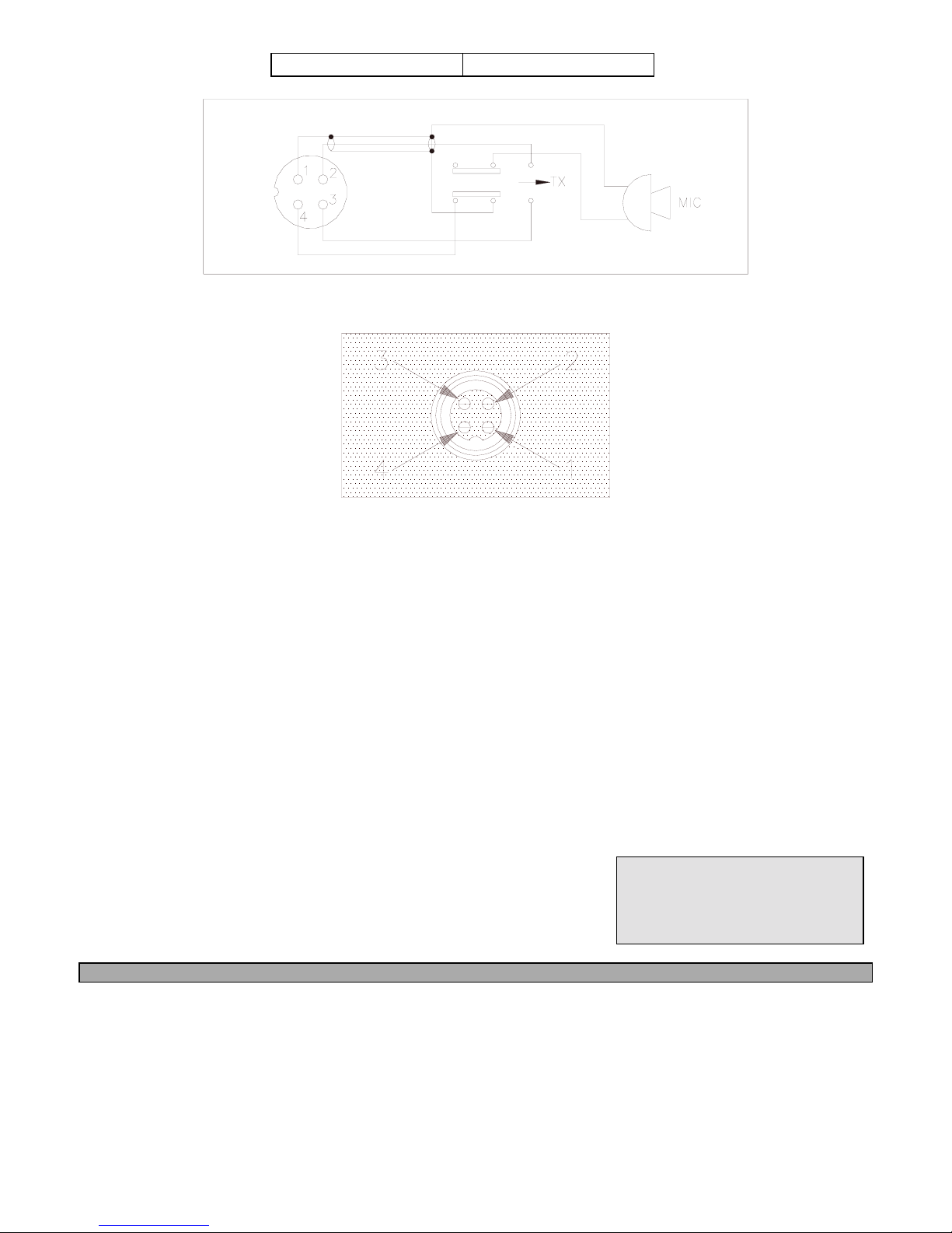
2.2 MICROPHONE
The receiver and transmitter are controlled by the push-to-talk switch on the microphone. Press the
switch and the transmitter is activated, release switch to receive. When transmitting, hold the
microphone two inches from the mouth and speak clearly in a normal voice. The radio comes complete
with a low impedance (500 ohm) dynamic microphone.
2.3 OPERATION
2.3.1 PROCEDURE TO RECEIVE
1. Be sure that power source, microphone and antenna are connected to the proper connectors before
going to the next step.

- 7 -
2. Turn VOL. knob clockwise to apply power to the radio.
3. Set the VOL. to a comfortable listening level.
4. Set the MODE switch to the desired mode.
5. Listen to the background noise from the speaker. Turn the SQ knob slowly clockwise until the noise
just disappears. The SQ is now properly adjusted. The receiver will remain quiet until a signal is
actually received. Do not advance the control too far or some of weaker signals will not be heard.
6. Set the CHANNEL selector switch to the desired channel.
7. Set the RF GAIN control fully clockwise for maximum receive gain.
8. Adjust the FINE/COARSE control to clarify the SSB signals or to optimize AM/FM signals.
2.3.2 PROCEDURE TO TRANSMIT
1. Select the desired channel of transmission
2. Set the MIC GAIN control fully clockwise.
3. If the channel is clear, depress the push-to-talk switch on the microphone and speak in a normal
voice.
2.4 ALTERNATE MICROPHONES AND INSTALLATION
For best results, the user should select a low impedance dynamic type microphone or a transistorized
microphone. Transistorized type microphones have a low output impedance characteristic. The
microphones must be provided with a four-lead cable. The audio conductor and its shielded lead
comprise two of the leads. The third lead is for transmit control and the fourth is for receiving control.
The microphone should provide the functions shown in schematic below (Figure 2-3).
4 WIRE MIC CABLE
Pin Number Mic Cable Lead
1 Audio Shield
2 Audio Lead
3 Transmit Control

- 8 -
4 Receive Control
Figure 2-3 Your Transceiver Microphone Schematic
Figure 2-5 Microphone plugs pins numbers viewed from rear of pin receptacle.
RCI-6900F HP
RCI-6900F TB
CHAPTER 3
CIRCUIT
DESCRIPTION
3.0 INTRODUCTION
This section explains the technical theory of operation for the RCI-6900F HP / RCI-6900F TB mobile
transceiver.
3.1 PLL CIRCUIT
The Phase Lock Loop (PLL) circuit is responsible for developing the receiver’s first local oscillator
signal and the transmitter’s exciter signal. The PLL circuit consists primarily of IC2, IC3, IC4, IC5

- 9 -
Q25, Q27, Q28, Q29 and Q61. The PLL circuit is programmed by the rotary channel switch GPS-0501.
The GPS-0501 communicates the correct binary data information to the programmable divider inside
of IC3. IC3 then controls the VCO (Voltage Controlled Oscillator), to oscillate on the correct
frequency. This signal is fed either into the receiver’s first mixer (for receive operation) or the
transmitter’s mixer (for transmit operation).
3.2 RECEIVER CIRCUIT
The incoming RF signal comes into the radio via the antenna and into the front-end pre-amp, Q17. The
RF signal is fed into the mixer circuit of the Q18 & Q19 and then into the AM IF section of the
receiver (depending on the mode of operation). The signal is then detected by either the AM detector or
product detector or then fed to the audio amplifier section of the receiver and finally out to the speaker.
3.3 TRANSMITTER MODULATION CIRCUIT
(i) The transmitter modulation circuit modulates the low-level RF signal from the PLL exciter circuit
with the user’s audio voice signal from the microphone. The audio from the microphone is then
amplified and fed into the transmit amplifier circuit.
(ii) If the transceiver is in the AM mode, the AF Power amplifier modulates the last RF amplifier,
which produces a true amplitude modulated RF signal.
3.4 TRANSMITTER AMPLIFIER CIRCUIT
The transmitter takes the basic exciter signal from the TX mixer and amplifies it through a series of
amplifiers consisting of Q50, Q51, Q49, Q47, Q48 and EPA010010B (only for RCI-6900F TB) where
it is sent out to the antenna connector.

- 10 -

- 11 -

- 12 -
RCI-6900F HP / RCI-6900F TB FREQUENCY COUNTER CIRCUIT DIAGRAM

- 13 -
RCI-6900F HP / RCI-6900F TB ECHO BOARD (EB-99) CIRCUIT DIAGRAM

- 14 -
RCI-6900F HP
RCI-6900F TB
CHAPTER 4
ALIGNMENT
4.0 REQUIRED TEST EQUIPMENT
!DC Power Supply (13.8VDC, 20A)
"RF Wattmeter (25~60 MHz, 100W)
#Multimeter (Digital)
$Automatic Modulation Meter
%Audio Signal Generator
&Frequency Counter (100 MHz)
'RF Signal Generator (100 MHz)
(Automatic Distortion Meter
)Oscilloscope (50 MHz)
*Sinad Meter
4.1 ALIGNMENT PROCEDURES
This transceiver has been aligned at the factory and does not require any adjustments at installation.
The required test equipment listed is used for the test setup or alignment shown in Figure 4-1
Transmitter Test Setup and Figure 4-2 Receiver Test Setup. This test setup is used in part or total
during the following adjustments and refer to Figure 4-3 for adjustment location.
4.1.1 PLL ALIGNMENT
ITEM U.U.T. SETTING ADJUST
POINT MEASUREMENT
VCO Voltage
Disconnect ‘short PCB” from TP7, TP8 and
TP9.
Set radio to Fr. Pool 6, CH 40 AM RX mode.
Set +10KHz/OFF switch to OFF position.
Connect Multimeter to TP2.
Connect Frequency Counter to TP11.
L15
VC1
6.5 VDC ±0.1
10.2400MHz ±20Hz
AM Frequency Set radio to Fr. Pool 1, CH 1 AM RX mode.
Set radio to Fr. Pool 6, CH 40 AM RX mode.
Connect Frequency Counter to TP3.
L45
L41
17.5500MHz ±20Hz
18.9600MHz ±20Hz
USB Frequency
Set radio to Fr. Pool 1, CH 1 USB RX mode.
Set radio to Fr. Pool 6, CH 40 USB RX mode.
Connect Frequency Counter to TP3.
L46
L42
17.5525MHz ±20Hz
18.9625MHz ±20Hz
LSB Frequency Set radio to Fr. Pool 1, CH 1 LSB RX mode.
Set radio to Fr. Pool 6, CH 40 LSB RX mode.
Connect Frequency Counter to TP3.
L47
L43
17.5475MHz ±20Hz
18.9575MHz ±20Hz
TX Frequency Set radio to Fr. Pool 1, CH 1 AM TX mode.
Connect Frequency Counter to TP3.
VR8 17.5500MHz ±20Hz
AM OSC Set radio to Fr. Pool 1, CH 1 AM TX mode.
Connect Frequency Counter to TP5.
L18 10.6950MHz ±10Hz
USB OSC Set radio to Fr. Pool 1, CH 1 USB TX mode.
Connect Frequency Counter to TP5.
L19 10.6925MHz ±10Hz
LSB OSC Set radio to Fr. Pool 1, CH 1 LSB TX mode.
Connect Frequency Counter to TP5.
L20 10.6975MHz ±10Hz
4.1.2 TRANSMITTER ALIGNMENT

- 15 -
ITEM U.U.T. SETTING ADJUST
POINT MEASUREMENT
TX Power Set radio to Fr. Pool 2, CH 19 AM TX mode.
Modulation Off.
Set radio to Fr. Pool 2, CH 19 USB TX mode.
AF signal 30mV, 1 KHz to microphone.
Connect Oscilloscope to TP12.
Set RF PWR Fully Clockwise.
Set FINE/COARSE Control to 12 o’clock.
L18,L37,L35,
L34
L35,L34
Maximum Output.
Maximum Output
and Balance.
AM APC
Set radio to Fr. Pool 2, CH 19 AM TX mode.
Connect Multimeter to TP8.
VR15
6VDC
SSB APC Set radio to Fr. Pool 2, CH 19 USB TX mode.
Connect Multimeter to TP8.
VR18 12.5VDC
BIAS Current Set radio to Fr. Pool 2, CH 19 USB TX mode.
Modulation Off.
Connect current meter to TP7(+) and TP9 (-)
Connect current meter to TP7 (+) and TP8 (-)
VR13
VR12 + VR11
10 mA
(50 mA + 50 mA) =
100 mA
AM TX Power Set radio to Fr. Pool 2, CH 19 AM TX mode.
Connect ‘short PCB” to TP7, TP8 and TP9.
Set RF PWR Fully Counter Clockwise.
Connect RF Power Meter to antenna jack.
VR15
VR19
10W (RCI-6900FHP)
50W (RCI-6900FTB)
2W
RF Power
Meter
Set radio to Fr. Pool 2, CH 19 AM TX mode.
Set RF PWR Fully Clockwise.
VR10 Adjust RF Power
meter needle until it
is in-between the
green and red bar on
TX PWR scale.
SSB ALC
Set radio to Fr. Pool 2, CH 19 USB TX mode.
AF signal 30mV, 1 KHz to microphone.
Set RF PWR Fully Clockwise.
VR14 25W (RCI-6900FHP)
100W (RCI-6900F
TB)
SSB Carrier
Balance
Set radio to Fr. Pool 2, CH 19 USB TX mode.
AF signal 30mV, 1 KHz to microphone.
Connect Oscilloscope to antenna jack.
VR7 Spurious Emission to
minimum.
CW TX Set radio to Fr. Pool 2, CH 19 CW TX mode.
Plug in CW key.
Disconnect the Mic Jack.
Connect AC Voltmeter to EXT SP.
VR9 200mV (Sine Wave)
SWR Meter Set radio to Fr. Pool 2, CH 19 AM TX mode.
Set SWR/S/RF switch to SWR position.
Connect 100 Ohm to antenna jack.
VR1 on
SWR P.C.B
Adjust SWR needle
until it is on the “2”
SWR scale.
AM Modulation
FM Modulation
Set radio to Fr. Pool 2, CH 19 AM TX mode.
Set radio to Fr. Pool 2, CH 19 FM TX mode.
AF signal 30mV, 1 KHz to microphone.
Set Mic Gain Fully Clockwise.
VR17 90%
4KHz
Frequency
Counter Adjust
Set radio to Fr Pool 2, CH 19 AM RX mode.
VC1 on
frequency
counter
Display should be
28.9150
4.1.3 RECEIVER ALIGNMENT

- 16 -
ITEM U.U.T. SETTING ADJUST
POINT MEASUREMENT
AM Sensitivity Set radio to Fr. Pool 2, CH 19 AM RX mode.
Set RF Gain Fully Clockwise.
Set SQ Fully Counter Clockwise.
Set VOL Control at 2 o’clock.
Set NB/ANL/OFF switch to OFF position.
Connect RF SG to antenna jack
Frequency 28.915 MHz, 1uV. Mod 30%.
Set radio to Fr. Pool 6, CH 40 AM RX mode.
RF SG setting 29.655 MHz.
Set radio to Fr. Pool 1, CH 1 AM RX mode.
RF SG setting 28.245 MHz.
L2,3,5,6,7,8,
9,10
L5,L6
L5,L6
Audio output > 2V
S/N > 10 dB.
For Balance between
CH 1 and CH 40.
USB Sensitivity
Set radio to Fr. Pool 2, CH19 USB RX mode.
Set VOL Control Fully Clockwise.
RF SG setting 28.916 MHz, 0.5uV. Mod off.
L11,L12 Audio Output >2V
S/N > 10dB.
LSB Sensitivity
Set radio to Fr. Pool 2, CH19 LSB RX mode.
Set VOL Control Fully Clockwise.
RF SG setting 28.914 MHz, 0.5uV. Mod off.
L11,L12 Audio Output >2V
S/N >10db.
FM Distortion Set radio to Fr. Pool 2, CH 19 FM RX mode.
Set MODE switch to FM mode.
RF SG setting 28.915 MHz, 1mV. Mod 3KHz.
L4 Audio output > 3V
Distortion < 10%
NB Adjust Set radio to Fr. Pool 2, CH 19 AM RX mode
RF SG setting 28.915 MHz, 100uV. Mod off.
Set NB/ANL/OFF switch to NB/ANL
position.
Connect Voltmeter to TP1.
L1 DC Voltage to max.
( > 2.0V )
AM Squelch Set radio to Fr. Pool 2, CH 19 AM RX mode.
Set SQ Control Fully Clockwise.
RF SG setting 28.915 MHz, 1 mV. Mod 30%.
VR4 Slowly Adjust very slowly
until squelch just
open
SSB Squelch Set radio to Fr. Pool 2, CH 19 USB RX mode.
Set SQ Control Fully Clockwise.
RF SG setting 28.915 MHz, 1 mV. Mod off.
VR3 Slowly Adjust very slowly
until squelch just
open
AM S/RF Meter
AM S-Meter
Set radio to Fr. Pool 2, CH 19 AM RX mode.
Set SWR/S/RF switch to S/RF position.
RF SG setting 28.915 MHz, 100uV. Mod 30%.
VR1 Meter needle to S9
on the S scale
SSB S-Meter
Set radio to Fr. Pool 2, CH 19 USB RX mode.
Set SWR/S/RF switch to S/RF position.
RF SG setting 28.916 MHz, 100uV. Mod off.
VR2 Meter needle to S9
on the S scale
Figure 4-1 Transmitter test setup

- 17 -
Figure 4-2 Receiver test setup

- 18 -
Figure 4-3 Main PCB Adjustment Location
RCI-6900F HP
RCI-6900F TB
CHAPTER 5
MAINTENANCE

- 19 -
5.0 PRECAUTIONS
The inherent quality of the solid-state components used in this transceiver will provide many years of
continuous use. Taking the following precautions will prevent damage to the transceiver.
(i) Never key the transmitter unless an antenna or suitable dummy load is connected to the antenna
receptacle.
(ii) Ensure that the input voltage does not exceed 16 VDC or fall below 11 VDC.
(iii) During alignment, do not transmit for more than 10 seconds at a time. Transmitting over long
periods can cause heat built-up and cause transmitter damage.
5.1 PERIODIC INSPECTION
This unit is aligned at the factory to deliver maximum performance. However, continued performance
cannot be expected without periodic inspection and maintenance. Important points to be checked
regularly are as follows;
Check Item Action
Whip antenna
(option)
If cracked or broken, replace it.
Coaxial cable If sheath is cracked, seal with
vinyl tape. If immersed with
water, install new coaxial cable.
Coaxial & power
plug connections
If loosened, reconnect. If
corroded, clean contacts.
Battery connection If corroded, clean power
terminals.
Ground terminal If corroded, clean terminal.
5.2 FUSE REPLACEMENT
To protect the equipment from serious damage, a fuse is provided on the power supply lines. The fuses
protect against over voltage / reverse polarity or internal fault of the equipment. If the fuse has blown,
first find out the cause of the trouble before replacing it. A fuse rated for more than the transceiver
requirement should not be used, since it may permanently damage the equipment. Damage due to over
fusing is not covered by the warranty.
RCI-6900F HP
RCI-6900F TB
CHAPTER 6
DIAGRAMS &
PARTS LIST

- 20 -
6.0 GENERAL
Information on most electrical and mechanical parts is included in the parts list. The reference
designators are in alphanumeric order.
6.1 ORDERING REPLACEMENT PARTS
Parts orders should be referred to the parts department at:
•Ranger Communications, Inc.
3377 Carmel Mountain Road
San Diego, CA 92121
Tel: 858-259-0287
Fax: 858-259-0437
This manual suits for next models
1
Table of contents
Other Ranger Transceiver manuals

Ranger
Ranger RCI-2900 User manual

Ranger
Ranger RCI-36 Series User manual

Ranger
Ranger AR-3500 User manual

Ranger
Ranger RCI-2950 User manual

Ranger
Ranger RCI-6900F25/150 User manual

Ranger
Ranger RCI-2950 User manual

Ranger
Ranger RCI-2970N4 User manual

Ranger
Ranger RCI-69FFC4 User manual

Ranger
Ranger Rcl-2970N2 User manual

Ranger
Ranger RCI-2900 User manual