Standart Horizont HX870 User manual

Page 1
HX870
HX870
6 Watt VHF/FM
Floating Marine Transceiver with DSC Class D and GPS
Owner’s Manual

Page 2
HX870
TABLE OF CONTENTS
Quick Reference Guide...............................................................................4
RADIO CARE................................................................................................5
1 GENERAL INFORMATION.....................................................................6
2 PACKING LIST.......................................................................................7
3 OPTIONAL ACCESSORIES...................................................................8
4 ONLINE WARRANTY REGISTRATION (in USA or Canada only).......8
5 ABOUT THIS RADIO..............................................................................9
5.1 PROHIBITED COMMUNICATIONS.............................................9
5.2 ABOUT VHF RADIO....................................................................9
5.3 DISTRESSAND HAILING (CHANNEL 16)..................................9
5.4 CALLINGANOTHER VESSEL (CHANNEL16 OR 9)................10
5.5 MAKING TELEPHONE CALLS..................................................11
5.6 BRIDGE CHANNELS 13AND 67..............................................11
5.7 AUTOMATED RADIO CHECK SERVICE..................................12
6 GETTING STARTED.............................................................................13
6.1 BATTERIESAND CHARGERS..................................................13
6.1.1 Battery Safety..................................................................13
6.1.2 Battery Installation/Removal............................................15
6.1.3 Battery Life Information....................................................15
6.1.4 Using the SBH-12 Charger Cradle...................................16
6.2 CONNECTINGAUSB DATATERMINALTOTHE PC...............17
6.3 CHECKING GPS SIGNAL(GPS STATUS DISPLAY)................18
6.4 CHANGING THE GPS TIME .....................................................19
6.5 CHANGING THE TIME LOCATION...........................................20
6.6 CHANGING THE TIME FORMAT..............................................20
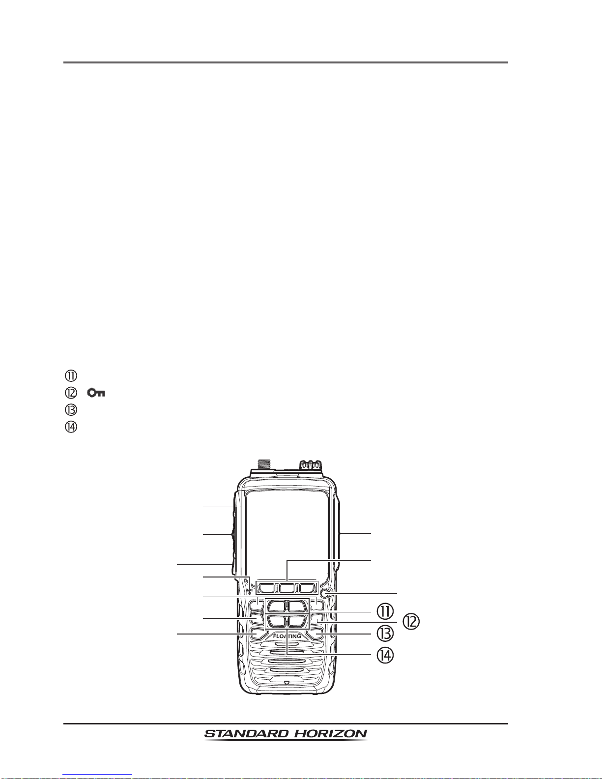
7 CONTROLS AND INDICATORS ..........................................................21
8 BASIC OPERATION.............................................................................25
8.1 INITIALSETUP..........................................................................25
8.2 RECEPTION..............................................................................25
8.3 TRANSMISSION........................................................................25
8.4 TRANSMITTIME - OUTTIMER (TOT)......................................26
8.5 SIMPLEX/DUPLEX CHANNELUSE..........................................26
8.6 USA, INTERNATIONAL,AND CANADAMODE........................26
8.7 NOAAWEATHER CHANNELS..................................................27
8.7.1 NOAAWeatherAlert........................................................27
8.7.2 NOAAWeatherAlert Testing............................................28
8.8 DUALWATCH (TO CHANNEL16)............................................28
8.9 SCANNING................................................................................28
8.9.1 Selecting the Scan Type..................................................29
8.9.2 Programming Scan Memory............................................30
8.9.3 Memory Scanning (M-SCAN)..........................................30
8.9.4 Priority Scanning (P-SCAN).............................................31
8.10 PRESET CHANNELS: INSTANTACCESS ...............................31
8.10.1 Programming.................................................................31
8.10.2 Operation.......................................................................32
8.10.3 Deletion..........................................................................32
9 GPS Operation.....................................................................................33
9.1 GPS Logger Operation..............................................................33
9.2 GPS Compass Display..............................................................33
9.3 GPS Information Display............................................................34
9.4 Numerical display with GPS status............................................34
10 DIGITAL SELECTIVE CALLING (DSC)...............................................35
10.1 GENERAL..................................................................................35
10.2 MARITIME MOBILE SERVICE IDENTITY(MMSI)....................35
10.2.1 What is an MMSI?..........................................................35
10.2.2 Programming the MMSI.................................................36
10.3 DSC DISTRESS CALL...............................................................37
10.3.1 Transmitting a DSC Distress Call...................................37
10.3.2 Receiving a DSC Distress Call......................................39
10.4 ALLSHIPS CALL.......................................................................41
10.4.1 Transmitting anAll Ships Call ........................................41
10.4.2 Receiving anAll Ships Call............................................42
10.5 INDIVIDUALCALL.....................................................................43
10.5.1 Setting up the Individual / Position Call Directory..........43
10.5.2 Setting up the Individual Call Reply...............................44
10.5.3 Enabling the Individual CallAcknowledgment ...............45
10.5.4 Transmitting an Individual Call.......................................45
10.5.5 Receiving an Individual Call...........................................48
10.5.6 Setting up the Individual Call Ringer..............................49
10.6 GROUP CALL............................................................................51
10.6.1 Setting up a Group Call..................................................51
10.6.2 Transmitting a Group Call..............................................53
10.6.3 Receiving a Group Call..................................................55
10.6.4 Setting up the Group Call Ringer...................................56
10.7 POSITION REQUEST...............................................................57
10.7.1 Setting up a Position Request Reply ............................57
10.7.2 Transmitting a Position Request toAnother Vessel.......58
10.7.3 Receiving a Position Request........................................60
10.7.4 Setting up a Position Request Ringer............................61
10.8 POSITION REPORT..................................................................61
10.8.1 Transmitting a DSC Position Report Call.......................62
10.8.2 Receiving a DSC Position Report Call...........................63
10.8.3 Navigating to a Position Report.....................................64
10.8.4 Stopping Navigation to a Position Report......................64
10.8.5 Saving a Position Report as a Waypoint........................64
10.8.6 Navigating to a Saved Waypoint....................................65
10.8.7 Setting up a Position Report Ringer...............................65
10.9 MANUALINPUT OFAGPS LOCATION (LAT/LON)..................66
10.10 AUTO POS POLLING................................................................67
10.10.1 Setting up the Polling Time Interval.............................67
10.10.2 Selecting Stations to beAutomatically Polled
(Tracked)......................................................................67
10.10.3 Enabling/DisablingAuto POS Polling...........................68
10.11 DSC TEST.................................................................................69
10.11.1 Programming MMSI into Individual Directory...............69
10.11.2 DSC Test call by using Individual/Position Directory....69
10.11.3 DSC Test Call by Manually Entering an MMSI.............70
10.12 POLLING CALL..........................................................................71
10.12.1 Transmitting a Polling Call toAnother Vessel ..............71
10.12.2 Receiving a Polling Call...............................................72
10.13 DSC LOG OPERATION.............................................................73
10.13.1 Reviewing and Resending a Transmitted Logged
Call...............................................................................73
10.13.2 Reviewing a Logged DSC Distress Call.......................74
10.13.3 Reviewing Other Logged Calls....................................75
10.13.4 Deleting a Call from the DSC Log Directory................75
11 NAVIGATION ........................................................................................77
11.1 OPERATION..............................................................................77
11.1.1 Operation .......................................................................77
11.1.2 Navigating to a Saved Waypoint....................................77
11.2 SETTING UP WAYPOINT DIRECTORY....................................78
11.2.1 Marking a Position..........................................................78
11.2.2 Adding a Waypoint .........................................................79
11.2.3 Editing a Waypoint.........................................................80
11.2.4 Deleting a Waypoint.......................................................81
11.2.5 Saving a DSC Position Call as a Waypoint....................81
11.2.6 Selecting the Waypoint Range.......................................82
11.2.7 Selecting theArrived Range...........................................82
12 CONFIGURATION................................................................................83
12.1 DIMMERADJUSTMENT............................................................83
12.2 LAMP.........................................................................................83
12.3 DISPLAY CONTRAST ...............................................................84
12.4 KEY BEEP.................................................................................84
12.5 BATTERY SAVER......................................................................85

Page 3
HX870
TABLE OF CONTENTS
12.6 STROBE LED............................................................................85
12.6.1 EMARGENCY LED........................................................85
12.6.2 WATER HAZARD LED...................................................86
12.7 SOFT KEYS...............................................................................87
12.7.1 KeyAssignment.............................................................87
12.7.2 Key Timer.......................................................................87
13 CHANNEL FUNCTION SETUP............................................................89
13.1 CHANNELGROUP....................................................................89
13.2 SCAN MEMORY........................................................................89
13.3 SCAN TYPE...............................................................................89
13.4 SCAN RESUME.........................................................................89
13.5 PRIORITY CHANNEL................................................................90
13.6 WEATHERALERT.....................................................................90
13.7 CHANNELNAME.......................................................................91
13.8 SUMMARY OF THE CANNEL FUNCTION SETUP...................92
14 DSC SETUP..........................................................................................93
14.1 INDIVIDUALDIRECTORY.........................................................93
14.2 INDIVIDUALREPLY..................................................................93
14.3 INDIVIDUALACKNOWLEDGMENT..........................................93
14.4 INDIVIDUALRINGER................................................................93
14.5 GROUP DIRECTORY................................................................93
14.6 POSITION REPLY.....................................................................94
14.7 AUTO POS POLLING................................................................94
14.8 AUTO POS INTERVAL..............................................................94
14.9 AUTO CH CHANGE..................................................................94
14.10 NOACT TIMER..........................................................................95
14.11 DSC BEEP.................................................................................95
14.12 SUMMARY OF THE DSC SETUP MENU..................................96
15 GPS SETUP..........................................................................................97
15.1 GPS ON/OFF.............................................................................97
15.2 POWER SAVE...........................................................................97
15.3 LOCATION FORMAT.................................................................98
15.4 TIME OFFSET...........................................................................98
15.5 TIMEAREA................................................................................99
15.6 TIME FORMAT...........................................................................99
15.7 UNIT OF MEASURE..................................................................99
15.8 PINNING..................................................................................100
15.9 SBAS (Satellite BasedAugmentation System)........................100
15.10 OUTPUT SENTENCES...........................................................101
15.11 LOGGER INTERVAL...............................................................101
15.12 LOG ERASE............................................................................102
15.13 SUMMARY OF THE GPS SETUP...........................................102
16 MAINTENANCE..................................................................................103
16.1 REPLACEMENT PARTS .........................................................103
16.2 FACTORY SERVICE ...............................................................104
16.3 TROUBLESHOOTING CHART................................................104
17 CHANNEL ASSIGNMENTS................................................................105
18 WARRANTY........................................................................................ 111
19 INSTALLATION OF THE SBT-13.......................................................115
20 SPECIFICATIONS ..............................................................................116
20.1 GENERAL................................................................................116
20.2 TRANSMITTER.......................................................................116
20.3 RECEIVER (for Voice and DSC)..............................................117
20.4 GPS.........................................................................................117
20.5 NMEAOUTPUT.......................................................................117
21 FCC RADIO LICENSE INFORMATION..............................................118
21.1 STATION LICENSE..................................................................118
21.2 RADIO CALLSIGN..................................................................118
21.3 CANADIAN SHIP STATION LICENSING.................................118
21.4 FCC / INDUSTRYCANADAINFORMATION...........................118
22 RF EXPOSURE SAFETY STATEMENT.............................................119
23 FCC NOTICE ......................................................................................120

Page 4
HX870
Quick RefeRence Guide
The HX870 is equipped with the E2O (Easy-To-Operate) system. Basic opera-
tion may be accomplished by following the procedure below:
POWER: Press and hold to turn on/off the transceiver.
PTT (Push-To-Talk):Activates the transmitter when pressed.
SQL: Press to display the SQL level setting screen, then press the CH▲
key to squelch or press the CH▼ to un-squelch the radio.
MIC: Speak slowly and clearly into the MIC hole having it about 1/2 to 1
inch (1.2 to 2.5 cm) away from your mouth while pressing the PTT key.
◄/►: Press to toggle the on-screen menus to right/left.
CLR: Press to cancel a function or menu selection.
MENU: Press to access MENU.
DISTRESS: Sends a DSC distress call. Lift the red cover, press the
DISTRESS once, then press and hold until the radio alarms.
Soft keys: These three programmable keys can be customized through
the setup menu mode. By pressing one of these keys briey, display the
key functions at the bottom of the display.
TX/BUSY Indicator: Press to toggle the on-screen menus up/down.
CH▲/CH▼: Press to change the operating channel.
: Press and hold to lock and unlock the keypad.
16/S: Press to recall channel 16. Press and hold to recall channel 9.
VOL−/VOL+: Press to adjust the speaker audio volume.

Page 5
HX870
Congratulations on your purchase of the HX870! Whether this is your rst
portable marine VHF transceiver, or if you have other STANDARD HORIZON
equipment, the STANDARD HORIZON organization is committed to ensuring
yourenjoymentof thishighperformance transceiver, which shouldprovide you
with many years of satisfying communications even in the harshest of envi-
ronments. STANDARD HORIZON technical support personnel stands behind
every product sold, and we invite you to contact us by phone (800) 767-2450.
We appreciate your purchase of the HX870, and encourage you to read this
manual thoroughly, so as to learn and fully understand the capabilities of the
HX870.
RADIO CARE
Before using the radio:
1. Itisrecommended the batterybe charged.Please see section“6.1.4 Using
the SBH-12 Charger Cradle” for details.
2. Insure the speaker microphone jack, antenna and battery are in place and
rmly tightened.
3. Care must be taken if the radio was dropped and a close inspection may
be needed to insure the radio case and gaskets are in adequate condition.
NOTE
This is to keep the rubber switches and speaker grill clean and in top
operating condition after exposure to water: Clean the radio with fresh
waterafterexposureto saltwaterbyrinsingtheradiounderasink faucet
or by dunking the radio in a bucket of fresh water. After washing, use
a soft cloth and thoroughly dry all parts of the radio.

Page 6
HX870
1 GENERAL INFORMATION
The STANDARD HORIZON HX870 Portable Marine transceiver is designed
to be used in USA, International, and Canadian Marine bands. The HX870 can
be operated from 11 to 16 VDC and has a switchable RF output power of 1 watt,
2 watts or 6 watts.
TheHX870 is capable of DSC(Digital Selective Calling)ITUClassD operation.
ClassD operation allows continuousreceiving of DigitalSelectiveCalling func-
tions on channel 70 even if the radio is receiving a call. The HX870 operates
on all currently-allocated marine channels which are switchable for use with
USA, International, or Canadian regulations. Emergency channel 16 can be
immediately selected from any channel by pressing the red 16/S key. NOAA
weather channel can also be accessed immediately by selecting [WX] on the
main menu screen.
With the internal high-performance GPS receiver, WASS and QZSS satellites
can be received.

Page 7
HX870
2 PACKING LIST
When the package containing the transceiver is rst opened, please check it
for the following contents:
HX870 Transceiver
CAT460*Antenna
SBR-13LI 7.4V 1800mAh Li-ion Battery Pack
SBH-12 Charger Cradle for HX870
SAD-11B 120VAC Wall Charger for SBH-12
E-DC-19A DC Cable with 12 V Cigarette Lighter Plug for SBH-12
SBT-13 Alkaline Battery Case forAAA x 5 pcs
Clip-22 Belt Clip
YS-05-01 Hand Strap
T9101606 USB Cable (Type USB “A” plug to Type USB mini “B” plug)
Owner’s Manual
* Antenna gain: -1.5 dBi
Impedance: 50 ohms

Page 8
HX870
3 OPTIONAL ACCESSORIES
MH-73A4B ...................................................Submersible Speaker/Microphone
MH-57A4B ................................................................Mini Speaker/Microphone
VC-24 ........................................................................................VOX Headset
SSM-55A .......................................................................Earpiece/Microphone
SSM-10 ..................... Submersible Speaker/Microphone with Earphone Jack
SEP-10 .........................................................................Earphone for SSM-10
CN-3 ........................................................... Radio-to-Ship’s-Antenna Adapter
SBH-12 ................................................................................... Charger Cradle
SBR-13 LI .................................................7.4V 1800mAh Li-ion Battery Pack
SBT-13 ...................................................Alkaline Battery Case (AAA x 5 pcs)
E-DC-19A .....................................DC Cable with 12 V Cigarette Lighter Plug
SAD-11B/C/U..................................................Wall Charger for the SBH-12
E-DC-6 .............................................................. DC Cable; plug and wire only
:“B” sufx is for use with 120 VAC (Type-A plug), “C” sufx is for use with 230
VAC (Type-C plug), and “U” sufx is for use with 230 VAC (Type-BF plug).
4 ONLINE WARRANTY REGISTRATION
(in USA or Canada only)
Please visit www.standardhorizon.com to register the HX870 Marine VHF. It
should be noted that visiting the website from time to time may be benecial
to you, as new products are released they will appear on the STANDARD
HORIZON website.
PRODUCT SUPPORT INQUIRIES
If you have any questions or comments regarding the use of the HX870, you
can visit the STANDARD HORIZON website to send an E-Mail or contact the
Product Support team at (800) 767-2450 M-F 8:00-5:00 PST.

Page 9
HX870
5 ABOUT THIS RADIO
5.1 PROHIBITED COMMUNICATIONS
The FCC prohibits the following communications:
• False distress or emergency messages:
• Messages to “any boat” except in emergencies and radio tests;
• Messages to or from a vessel on land;
• Transmission while on land;
• Obscene, indecent, or profane language (potential ne of $10,000).
5.2 ABOUT VHF RADIO
The radio frequencies used in the VHF marine band lie between 156 and 158
MHzwithsome shore stations available between 161and163MHz.Themarine
VHF band provides communications over distances that are essentially “line of
sight” (VHF signals do not travel well through objects such as buildings, hills
or trees). Actual transmission range depends much more on antenna type,
gain and height than on the power output of the transmitter. On a xed mount
25W radio transmission expected distances can be greater than 15 miles, for
a portable 6W radio transmission the expected distance can be greater than
5 miles in “line of sight”.
5.3 DISTRESS AND HAILING (CHANNEL 16)
Channel 16 is known as the Hail and Distress Channel. An emergency may
be dened as a threat to life or property. In such instances, be sure the
transceiver is on and set to CHANNEL 16. Then use the following procedure:
1. Pressthe PTT (Push-To-Talk)buttonand say “Mayday,Mayday,Mayday.
This is , , ” (your vessel’s name).
2. Then repeat once: “Mayday, ” (your vessel’s name).
3. Nowreportyourpositionin latitude/longitude, orbygivingatrueormagnetic
bearing (state which) to a well-known landmark such as a navigation aid
or geographic feature such as an island or harbor entry.
4. Explain the nature of your distress (sinking, collision, aground, re, heart
attack, life-threatening injury, etc.).
5. State the kind of assistance your desire (pumps, medical aid, etc.).
6. Report the number of persons aboard and condition of any injured.
7. Estimate the present seaworthiness and condition of your vessel.
8. Giveyourvessel’sdescription: length, design (power orsail),colorandother
distinguishing marks. The total transmission should not exceed 1 minute.
9. End the message by saying “OVER”. Release the PTT button and listen.
10. Ifthereisnoanswer, repeattheaboveprocedure.Ifthereis stillnoresponse,
try another channel.

Page 10
HX870
NOTE
The HX870 has the DSC Distress calling, that can transmit a distress
call digitally to all ships with compatible DSC radios. Refer to section
“10 DIGITAL SELECTIVE CALLING (DSC)”.
5.4 CALLING ANOTHER VESSEL (CHANNEL 16 OR 9)
Channel 16 may be used for initial contact (hailing) with another vessel.
However, its most important use is for emergency messages. This channel
must be monitored at all times except when actually using another channel.
It is monitored by the U.S. and Canadian Coast Guards and by other vessels.
Use of channel 16 for hailing must be limited to initial contact only. Call-
ing should not exceed 30 seconds, but may be repeated 3 times at 2-minute
intervals. In areas of heavy radio trafc, congestion on channel 16 resulting
from its use as a hailing channel can be reduced signicantly in U.S. waters
by using channel 9 as the initial contact (hailing) channel for non-emergency
communications. Here, also, calling time should not exceed 30 seconds but
may be repeated 3 times at 2-minute intervals.
Prior to making contact with another vessel, refer to the channel charts in this
manual, and select an appropriate channel for communications after initial
contact. For example, Channels 68 and 69 of the U.S. VHF Charts are some
of the channels available to non-commercial (recreational) boaters. Monitor
your desired channel in advance to make sure you will not be interrupting
other trafc, and then go back to either channel 16 or 9 for your initial contact.
When the hailing channel (16 or 9) is clear, press the PTT button and state the
name of the other vessel you wish to call and then “this is” followed by the
name of your vessel and your Station License (Call Sign) then release the PTT
button. When the other vessel returns your call, immediately request another
channel by pressing the PTT button and saying “go to”, the number of the
other channel, say “over” and release the PTT button. Then switch to the new
channel. When the new channel is not busy, call the other vessel.
Afteratransmission, say “over”, andreleasethe PTT button. When allcommu-
nicationwith the other vessel is completed, endthe last transmissionby stating
your Call Sign and the word “out”. Note that it is not necessary to state your
Call Sign with each transmission, only at the beginning and end of the contact.
Remember to return to Channel 16 when not using another channel. Some
radios automatically monitor Channel 16 even when set to other channels or
when scanning.

Page 11
HX870
5.5 MAKING TELEPHONE CALLS
To make a radiotelephone call, use a channel designated for this purpose.
The fastest way to learn which channels are used for radiotelephone trafc
is to ask at a local marina. Channels available for such trafc are designated
Public Correspondence channelson the channel chartsinthismanual.Some
examples for USAuse are Channels 24, 25, 26, 27, 28, 84, 85, 86, and 87. Call
the marine operator and identify yourself by your vessel’s name. The marine
operator will then ask you how you will pay for the call (telephone credit card,
collect, etc.) and then link your radio transmission to the telephone lines.
Themarine telephone company managingthe VHF channel youareusing may
charge a link-up fee in addition to the cost of the call.
5.6 BRIDGE CHANNELS 13 AND 67
Channel 13 is used at docks, bridges and by vessels maneuvering in port.
Messages on this channel must concern navigation only, such as meeting and
passing in restricted waters.
Channel 67 is used for navigational trafc between vessels.
Byregulation,power is normally limitedto1 Watt on thesechannels.Yourradio
is programmed to automatically reduce power to this limit on these channels.
However, in certain situations it may be necessary to temporarily use a higher
power. See Page xx for means to temporarily override the low-power limit on
these two channels.

Page 12
HX870
5.7 AUTOMATED RADIO CHECK SERVICE
In areas across the country, Sea Tow offers boaters a way to conduct radio
checks. To use Sea Tow’s free Automated Radio Check service, simply tune
your VHF radio to the appropriate channel for your location and conduct a
radio check as you typically would. Upon releasing your radio’s microphone,
the system will play an automated message and relay your transmission back
to you, thereby letting you know how your signal will sound to other boaters.
The Automated Radio Check Service is currently available in the areas listed
below.
West Coast Sea Tow Newport/LA - Ch. 27
Sea Tow San Diego - Ch. 27
Northeast Sea Tow Portland-Midcoast (Maine) - Ch. 27
Sea Tow Boston - Ch. 27
Sea Tow South Shore (Mass.) - Ch. 28
Sea Tow Rhode Island - Ch. 24
Sea Tow Eastern Long Island - Ch. 27
Sea Tow Huntington (N.Y.) - Ch. 27
Sea Tow Manasquan (N.J.) - Ch. 28
Mid-Atlantic Sea Tow Northern Chesapeake (Md.) - Ch. 28
Sea Tow Central Chesapeake (Md.) - Ch. 27
Sea Tow Hampton Roads (Va.) - Ch. 28
North Carolina Sea Tow Wrightsville Beach - Ch. 28
Sea Tow Ocean Isle Beach - Ch. 28
Florida Sea Tow Sebastian - Ch. 28
Sea Tow Fort Lauderdale - Ch. 27
Sea Tow Charlotte Harbor - Ch. 24
Sea Tow Tampa Bay - Ch. 27
Sea Tow Horseshoe Beach - Ch. 27
Sea Tow Carrabelle/St. Marks - Ch. 27
Sea Tow Pensacola/Orange Beach (Ala.) - Ch. 27

Page 13
HX870
6 GETTING STARTED
NOTE
Before operating the HX870 for the rst time, it is recommended that
the battery be charged. Please see section “6.1.4 Using the SBH-12
Charger Cradle” for details.
6.1 BATTERIES AND CHARGERS
If the radio has never been used, or its charge is depleted, it may be charged
by connecting the SBH-12 Charger Cradle with the SAD-11B battery charger,
as shown in the illustration. If 12V DC power is available, the E-DC-19A DC
Cable with 12 V Cigarette Lighter Plug or the optional E-DC-6 DC Cable may
be used for charging the battery. The SAD-11B, E-DC-19A and E-DC-6 will
charge a completely discharged SBR-13LI battery pack in about 3 hours.
The SBR-13LI is a high performance Li-ion battery providing high capacity in
a compact package.
SBR-13LI Rechargeable Battery Pack
Capacity 1800 mAh
Nominal Voltage 7.4 V
Temperature Range Minimum Maximum
°C °F °C °F
Charge 5 41 35 95
Discharge –20 –4 60 140
Storage –10 14 35 95
CAUTION
To avoid risk ofexplosionandinjury, SBR-13LI batterypack should only
be removed, charged or recharged in non-hazardous environments.
6.1.1 Battery Safety
Battery packs for your transceiver contain Li-ion batteries. This type of battery
stores a charge powerful enough to be dangerous if misused or abused,
especially when removed from the transceiver. Please observe the following
precautions:
DO NOT SHORT BATTERY PACK TERMINALS: Shorting the terminals that
powerthetransceivercancausesparks,severeoverheating,burns,andbattery
cell damage. If the short is of sufcient duration, it is possible to melt battery
components. Do not place a loose battery pack on or near metal surfaces or

Page 14
HX870
objects such as paper clips, keys, tools, etc. When the battery pack is installed
on the transceiver, the terminals that transfer current to the transceiver are not
exposed.Theterminalsthatareexposed on the battery pack when it is mounted
on the transceiver are charging terminals only and do not constitute a hazard.
DO NOT INCINERATE: Do not dispose of any battery in a re or incinerator. The
heat of re may cause battery cells to explode and/or release dangerous gases.
Battery Maintenance
For safe and proper battery use, please observe the following:
Battery packs should be charged only in non-hazardous environments;
Use only STANDARD HORIZON-approved batteries;
Use only a STANDARD HORIZON, (a Marine Division of YAESU USA)
approved charger. The use of any other charger may cause permanent
damage to the battery.
Follow charging instructions provided with the chargers.
Keep the battery contacts clean.
Battery Storage
Store the batteries in a cool place to maximize storage life. Since batteries are
subject to self-discharge, avoid high storage temperatures that cause large
self-discharge rates.After extended storage, a full recharge is recommended.
Battery Recycling
DO NOT PLACE USED BATTERIES IN YOUR REGULAR TRASH!
LI-ION BATTERIES MUST BE COLLECTED, RECYCLED OR DISPOSED
OF IN AN ENVIRONMENTALLY SOUND MANNER.
The incineration, land lling or mixing of Li-ion batteries with
the municipal solid waste stream is PROHIBITED BY LAW
in most areas.
Return batteries to an approved Li-ion battery recycler. This
may be where you purchased the battery.
Contact your local waste management ofcials for other
information regarding the environmentally sound collection,
recycling and disposal of Li-ion batteries.

Page 15
HX870
6.1.2 Battery Installation/Removal
1. To install the battery pack, slide the battery cover lock switch to the
“UNLOCK” position, then press “PUSH” to open the battery cover. Install
the battery pack aligning it to the battery contacts until it clicks. Attach the
battery cover, then slide the battery cover lock switch to the “LOCK” posi-
tion.
2. Toremovethe battery pack, turnthe transceiver off,openthe battery cover,
then remove the battery pack.
NOTE
Thebatterylockmustbe setto“LOCK”positiontoensurewater integrity
and from the battery coming loose.
6.1.3 Battery Life Information
When the battery charge is almost depleted, a “ ” icon
will appear on the display. When the “ ” icon appears, it
is recommended that you charge the battery soon.
HIUSA
LAT/LON
23°
56.890E
123°
56.890W
Oct/25 09:56AM
DATE
STATUS
SEARCH
65
A
BUSY
: Full battery power
: Enough battery power
: Low battery power
: Poor battery power
: Charge (or replace) the battery

Page 16
HX870
6.1.4 Using the SBH-12 Charger Cradle
1. Turn the transceiver off.
2. Insert the DC plug from the SAD-
11B intotheDC jackontheSBH-12
bottom panel, then plug the SAD-
11B into the AC line outlet.
3. Insert the HX870 (with the battery
pack)intothe SBH-12; the antenna
shouldbeattheleftsidewhenview-
ing the charger from the front.
4. If the HX870 is inserted correctly,
the HX870’s LCD display will show
the battery charging icon. A fully-
discharged pack will be charged
completely in approximately 3
hours.
5. When charging is completed, the battery charging icon will disappear.
CAUTION
The SBH-12 is NOT designed to be waterproof. Charge the radio in
a dry location.
NOTE
The SBH-12 is only designed for the charging of the HX870’s battery,
and is not suitable for other purposes. The SBH-12 may contribute
noise to TV and radio reception in the immediate vicinity, so we do not
recommend its use adjacent to such devices.

Page 17
HX870
6.2 CONNECTING A USB DATA TERMINAL TO THE PC
The HX870 outputs the following NMEA 0183 sentences 9600: GLL, GGA,
GSA, GSV, RMC, DSC and DSE.
If you have further inquires, please feel free to contact Product Support at:
Phone: (800) 767-2450
Email: [email protected]
To connect a PC, use the supplied USB cable to connect the HX870 to the
USB jack of the PC.
NOTE
When mounting the HX870 inside of a cabin where GPS reception is
limited, choose a place where GPS satellite reception is good enough
referring to the GPS status display.

Page 18
HX870
6.3 CHECKING GPS SIGNAL (GPS STATUS DISPLAY)
TheHX870 hasa GPS status display whichshowsthesatellites currently being
received,alongwithagraphical(bar-graph)representationofthe relative signal
strengths from the satellites.
When the HX870 receives the GPS signal through the
internal GPS, a small satellite icon or “ ” will appear
on the top right corner of the display and your current
location (latitude/longitude) is shown on the display.
(GPS StatuS DiSPlay moDe)
HIUSA
LAT/LON
23°
56.890E
123°
56.890W
Oct/25 09:56AM
DATE
STATUS
FIX 3D
65
A
BUSY
1. PresstheMENU keytodisplay“MENU”, then
select “GPS” with the CH▲/CH▼/◄/►key.
GPS INFO
COMPASS
ENTER
GPS
GPS STATUS
BACK
HIUSA
LAT/LON
23°
56.890E
123°
56.890W
Oct/25 09:56AM
DATE
STATUS
SEARCH
65
A
BUSY
2. Press the [SELECT] soft key, then select
“GPS STATUS” with the CH▲/CH▼ key.
3. Press the [ENTER] soft key to display the
GPS status currently being received.
4. Press the CLR key to return to radio opera-
tion.
NOTE
When the HX870 is rst turned on, it may take several minutes to
compute a x of your position. This is normal, as the HX870 is down-
loading “almanac” information from the GPS satellites.

Page 19
HX870
6.4 CHANGING THE GPS TIME
From the factory the HX870 shows GPS satellite time or UTC (Universal Time
Coordinated) time.Atime offset is needed to show the local time in your area.
The time offset must be changed in order for the radio to display the current
time in your area. See the Offset Time Table below.
offSet time table
1. Pressthe MENU key to display“MENU”,then
select “SETUP” with the CH▲/CH▼/◄/►
key.
DSC SETUP
GM SETUP
BACK
SETUP
WAYPOINT SETUP
CH SETUP
GPS SETUP
ATIS SETUP
SELECT
GPS ON/OFF
POWER SAVE
DIRECTION
LOCATION FORMAT
TIME OFFSET
TIME AREA
TIME FORMAT
GPS SETUP
BACK SELECT
ON
+09:00
BACK
GPS SETUP
+09:30
+10:00
+10:30
+11:00
ENTER
TIME OFFSET
2. Select“GPS SETUP”with theCH▲/CH▼ key.
3. Press the [SELECT] soft key, then select
“TIME OFFSET” with the CH▲/CH▼ key.
4. Pressthe[SELECT] softkey, then press the
CH▲/CH▼ key to select time offset of your
location. See illustration above to nd your
offset time. If “00:00” is assigned, the time
is the same as UTC or GPS satellite time.
5. Pressthe[ENTER] softkeytostorethetime
offset.
6. Press the CLR key to return to radio operation.

Page 20
HX870
6.5 CHANGING THE TIME LOCATION
This menu selection allows the radio to show UTC time or local time with the
offset.
1. Pressthe MENU key to display“MENU”,then
select “SETUP” with the CH▲/CH▼/◄/►
key.
DSC SETUP
GM SETUP
BACK
SETUP
WAYPOINT SETUP
CH SETUP
GPS SETUP
ATIS SETUP
SELECT
GPS ON/OFF
POWER SAVE
DIRECTION
LOCATION FORMAT
TIME OFFSET
TIME AREA
TIME FORMAT
GPS SETUP
BACK SELECT
ON
UTC
BACK
GPS SETUP
LOCAL
ENTER
TIME AREA
2. Select“GPS SETUP”with theCH▲/CH▼ key.
3. Press the [SELECT] soft key, then rotate
the CH▲/CH▼ key to “TIME AREA”.
4. Press the [SELECT] soft key.
5. Press the CH▲/CH▼ key to select “UTC” or
“LOCAL”.
6. Press the [ENTER] soft key to store the
selected setting.
7. Press the CLR key to return to radio opera-
tion.
6.6 CHANGING THE TIME FORMAT
This menu selection allows the radio to setup to show time in 12-hour or
24-hour format.
1. Pressthe MENU key to display“MENU”,then
select “SETUP” with the CH▲/CH▼/◄/►
key.
DSC SETUP
GM SETUP
BACK
SETUP
WAYPOINT SETUP
CH SETUP
GPS SETUP
ATIS SETUP
SELECT
GPS ON/OFF
POWER SAVE
DIRECTION
LOCATION FORMAT
TIME OFFSET
TIME AREA
TIME FORMAT
GPS SETUP
BACK SELECT
ON
24hour
BACK
GPS SETUP
12hour
ENTER
TIME FORMAT
2. Select“GPS SETUP”with theCH▲/CH▼ key.
3. Pressthe[SELECT] softkey,then rotatethe
CH▲/CH▼ key to select “TIME FORMAT”.
4. Press the [SELECT] soft key.
5. Press the CH▲/CH▼ key to select “12
HOUR” or “24 HOUR”.
6. Press the [ENTER] soft key to store the
selected setting.
7. Press the CLR key to return to radio opera-
tion.
Table of contents
Other Standart Horizont Transceiver manuals

Standart Horizont
Standart Horizont HX407 User manual

Standart Horizont
Standart Horizont HX500S User manual

Standart Horizont
Standart Horizont Eclipse DSC+ GX1150 User manual

Standart Horizont
Standart Horizont GX2100 User manual

Standart Horizont
Standart Horizont HX250S User manual

Standart Horizont
Standart Horizont C520 User manual

Standart Horizont
Standart Horizont HX380 User manual