Harvia WHP1500 Guide

07032006H
Instructions for installation of Steel Chimney
Èíñòðóêöèÿ ïî ìîíòàæó ñòàëüíîãî äûìîõîäà
Steel Chimney
Ñòàëüíîé äûìîõîä
EN
RU
Harvia Oy
PL12
40951 Muurame
Finland
www.harvia.fi

WHP1000
Length: 1.0 m
Length of isolated
component: 970 mm
Äëèíà 1,0 ì
Äëèíà èçîëèðîâàííîãî
÷àñòè 970 ìì
Rain cap
Îãîëîâîê Rain flange
Äîæäåâîé ôëàíåö
WHP1500
Standard delivery
Ñòàíäàðòíàÿ êîìïëåêòàöèÿ
Steel Chimney extensions
Äîïîëíèòåëüíûå ìîäóëè
WHP500
Length: 0.5 m
Length of isolated
component: 470 mm
Äëèíà 0,5 ì
Äëèíà èçîëèðîâàííîãî
÷àñòè 470 ìì
Steel Chimney 1.5 m
Äûìîõîä ñòàëüíîé 1,5 ì
Smoke pipe 1.0 m
(stainless steel)
Äûìîâàÿ òðóáà 1,0 ì
(ïîëèðîâàííàÿ íåðæàâåþùàÿ ñòàëü)
Lead-through flange
Ïðîõîäíîé ôëàíåö
Note! Extensions increase the total length of the steel
chimney by the length of their isolated component.
Âíèìàíèå! Äîïîëíèòåëüíûå ìîäóëè óâåëè÷èâàþò ïîëíóþ
äëèíó ñòàëüíîãî äûìîõîäà íà äëèíó ñâîåé èçîëèðîâàííîé
÷àñòè.

Product description
Îïèñàíèå èçäåëèÿ
Standard number
Íîìåð ñòàíäàðòà èçäåëèÿ
Temperature level (max. nominal chimney gas temperature of fireplace 600 °C)
Òåïëîâîé êëàññ (íîìèíàëüíàÿ òåìïåðàòóðà äûìîâûõ ãàçîâ ìàêñ. 600 °C)
Pressure level (N1: low pressure chimney)
Êëàññ äàâëåíèÿ (N1: òðóáà íèçêîãî äàâëåíèÿ)
Condensate (condensation) resistance rating
(D: dry operating conditions, chimney gas temperature is above water condensation level)
Êëàññ óñòîé÷èâîñòè ê êîíäåíñàòó
(D: ñóõèå óñëîâèÿ, òåìïåðàòóðà äûìîâîãî ãàçà ïðåâûøàåò òî÷êó êîíäåíñàöèè âîäû)
Corrosion resistance (Vm-L20: based on the material rating AISI304)
(070: thickness of smoke-pipe walling)
Êëàññ óñòîé÷èâîñòè ê êîððîçèè (Vm-L20: îñíîâàí íà êëàññèôèêàöèè ìàòåðèàëîâ AISI304)
(070: òîëùèíà ñòåíêè òðóáû äûìîõîäà)
Sootfire resistance (G: sootfire resistant) and distance to combustible material (in millimetres)
Êëàññ óñòîé÷èâîñòè ê ïðîãîðàíèþ (G: óñòîé÷èâ) è ðàññòîÿíèå äî âîñïëàìåíÿþùèõñÿ ìàòåðèàëîâ (â ìèëëèìåòðàõ)
CONTENTS
1. General information ................................................... 4
2. Protective distances .................................................. 5
3. Connecting the parts of the Steel Chimney................... 6
4. Installing the rain flange............................................. 7
5. Installing the rain cap ................................................ 8
6. Installing the lead-through flange................................. 8
ÎÃËÀÂËÅÍÈÅ
1. Îáùàÿ èíôîðìàöèÿ.................................................................... 4
2. Áåçîïàñíîå ðàññòîÿíèå .............................................................. 5
3. Ñîåäèíåíèå ýëåìåíòîâ äûìîõîäà ìåæäó ñîáîé........................ 6
4. Óñòàíîâêà äîæäåâîãî ôëàíöà .................................................... 7
5. Óñòàíîâêà îãîëîâêà äûìîõîäà .................................................... 8
6. Óñòàíîâêà ïðîõîäíîãî ôëàíöà ................................................... 8
EN RU
0809
Harvia Oy, PL 12, 40951 Muurame, Finland
06
0809-CPD-0548
EN 1856-1
Steel Chimney
Multi-wall
T600 - N1 - D - VmL20070 - G100
Compressive strength
Maximum load: 5.0 m of chimney elements
Flow resistance
NPD
Thermal resistance
NPD
Sootfire resistance: Yes
Flexural strength
Tensile strength: 5.0 m
Non-vertical installations: not allowed.
Wind load:
Free standing height: 2.0 m above last support.
Maximum spacing of lateral supports:
3.0 m
Freeze thaw resistance: Yes
0809
Harvia Oy, PL 12, 40951 Muurame, Finland
06
0809-CPD-0548
EN 1856-1
Äûìîõîä ñòàëüíîé
Ìíîãîñëîéíûé
T600 - N1 - D - VmL20070 - G100
Ïðî÷íîñòü ïðè ñæàòèè
Ìàêñèìàëüíàÿ íàãðóçêà 5,0 ì ýëåìåíòîâ ñòàëüíîãî äûìîõîäà
Ñîïðîòèâëåíèå ïîòîêó
NPD
Òåðìîèçîëÿöèîííûå ñâîéñòâà
NPD
Ñòîéêîñòü ê ïðîãîðàíèþ: Óñòîé÷èâ
Ïðî÷íîñòü ïðè èçãèáå
Ïðî÷íîñòü ïðè ðàñòÿæåíèè: 5,0 ì
Èíîé, êðîìå âåðòèêàëüíîãî ìîíòàæà: Íå äîïóñêàåòñÿ
Âåòðîâàÿ íàãðóçêà:
Âûñîòà ñâîáîäíî ñòîÿùåãî ýëåìåíòà: 2,0 ì îò ïîñëåäíåé
îïîðû
Ìàêñèìàëüíîå ðàññòîÿíèå ìåæäó ïîïåðå÷íûìè
îïîðàìè â ïîìåùåíèè: 3,0 ì
Ñòîéêîñòü ê öèêëó «çàìåðçàíèå-îòòàèâàíèå»: Óñòîé÷èâ
Steel Chimney / Äûìîõîä ñòàëüíîé EN 1856-1 - T600 - N1 - D - VmL20070 - G100
NPD = no performance determined NPD = íå íîðìèðóåòñÿ

4
EN RU
The steel chimney is a CE-standardised chimney
for removal of chimney gas in solid fuel run
saunas and iron stoves and fireplaces using solid
fuel for heating. Maximum nominal chimney gas
temperature of the furnace joint is 600 oC. The
cross-section of the chimney is round and the
diameter 220 mm. The outer casing material is 0.5
mm stainless steel. The diameter of the smoke pipe
is 115 mm and it is made out of 0.7 mm stainless
steel. The insulation material is mineral wool.
Openings need to be made to the intermediate
floor and the roof and their minimum size is defined
by the protective distances. When the fireplace is
used a considerable heating takes place and the
chimney needs to be protected with e.g. steel
mesh in case it is exposed to touch. The protection,
however, should not interfere with the ventilation
around the pipe. There is no need for protection if
the chimney is installed in a sauna. The chimney
shouldn’t be encapsulated.
The maximum height of the steel chimney is five
metres while the permissible maximum for the self-
supporting element (e.g. the element above the
roof) is two metres. The steel chimney can only be
mounted in a vertical position. The chimney should
stand to the height of maximum 800 mm at the
ridge of the roof. Refer to pictures 1 and 2.
Figure 1. Cross profile of the Steel Chimney installation
Ðèñóíîê 1. ×åðòåæ ïîïåðå÷íîãî ðàçðåçà ìîíòàæà ñòàëüíîãî äûìîõîäà
A Rain cap Îãîëîâîê
B Upper end Âåðõíèé òîðöîâûé ýëåìåíò
C Steel Chimney extension 1 m Äîïîëíèòåëüíûé ìîäóëü 1 ì
D Rain flange (rubber) Äîæäåâîé ôëàíåö (ìàòåðèàë – ðåçèíà)
E Minimum distance 100 mm Ìèíèìàëüíîå ðàññòîÿíèå 100 ìì
F
100 mm fire resistance rated
mineral wool (pack the wool so
that it supports the chimney)
100 ìì îãíåñòîéêàÿ ìèíåðàëüíàÿ
âàòà (óêëàäûâàåòñÿ òàê, ÷òîáû îíà
ôèêñèðîâàëà äûìîõîä)
G Lead-through flange Ïðîõîäíîé ôëàíåö
H Steel Chimney 1.5 m Îñíîâíîé ìîäóëü 1,5 ì
I
Smoke pipe 1.0 m,
stainless steel (cut to the
appropriate length)
Äûìîâàÿ òðóáà 1,0 ì, ïîëèðîâàííàÿ
íåðæàâåþùàÿ ñòàëü (ïðè íåîáõîäèìîñòè
îáðåçàåòñÿ äî òðåáóåìîé äëèíû)
Verify the protective distances required for the furnace from the installation instructions!
Òðåáîâàíèÿ ê áåçîïàñíûì ðàññòîÿíèÿì òîïêè íåîáõîäèìî óòî÷íèòü â èíñòðóêöèè ïî
åå ìîíòàæó!
Ñòàëüíîé äûìîõîä ñ ìàðêèðîâêîé ÑÅ ïðåäíàçíà÷åí
äëÿ îòâîäà äûìîâûõ ãàçîâ èç êàìåíîê è êàìèíîâ,
èñïîëüçóþùèõ òâåðäûå âèäû òîïëèâà. Íîìèíàëüíàÿ
òåìïåðàòóðà äûìîâûõ ãàçîâ òîïêè, ïîäñîåäèíåííîé ê
äûìîõîäó, íå äîëæíà ïðåâûøàòü 600 oC.  ïîïåðå÷íîì
ñå÷åíèè äûìîõîä èìååò êðóãëóþ ôîðìó ñ äèàìåòðîì 220
ìì. Íàðóæíàÿ ðóáàøêà èçãîòîâëåíà èç íåðæàâåþùåé
ñòàëè òîëùèíîé 0,5 ìì. Äèàìåòð âíóòðåííåé òðóáû
ñîñòàâëÿåò 115 ìì, è îíà èçãîòîâëåíà èç íåðæàâåþùåé
ñòàëè òîëùèíîé 0,7 ìì.  êà÷åñòâå èçîëÿöèîííîãî
ìàòåðèàëà ïðèìåíÿåòñÿ ìèíåðàëüíàÿ âàòà. Îñíîâíîé
ìîäóëü äëèíîé 1,5 ì êîìïëåêòóåòñÿ îãîëîâêîì, äîæäåâûì
è ïðîõîäíûì ôëàíöàìè, íåèçîëèðîâàííîé òðóáîé äëèíîé
1 ì. Äîïîëíèòåëüíûå ìîäóëè äëèíîé 0,5 ì è 1,0 ì ñëóæàò
äëÿ óâåëè÷åíèÿ äëèíû äûìîõîäà äî òðåáóåìîé.
Äëÿ ïðîâåäåíèÿ äûìîõîäà â ìåæýòàæíîì ïåðåêðûòèè
è êðîâëå íåîáõîäèìî ïðîäåëàòü îòâåðñòèÿ, ÷üè
ðàçìåðû äîëæíû áûòü ðàññ÷èòàíû ñ ó÷åòîì áåçîïàñíûõ
ðàññòîÿíèé. Âî âðåìÿ èñïîëüçîâàíèÿ òîïêè äûìîõîä
çíà÷èòåëüíî ðàçîãðåâàåòñÿ, è åñëè äî íåãî ìîæíî
äîòðîíóòüñÿ, îí äîëæåí áûòü çàùèùåí. Çàùèòà íå
äîëæíà, òåì íå ìåíåå, ïðåïÿòñòâîâàòü öèðêóëÿöèè
âîçäóõà âîêðóã äûìîõîäà. Â ïîìåùåíèè ñàóíû çàùèòû
íå òðåáóåòñÿ. Äûìîõîä íåëüçÿ çàøèâàòü ïîëíîñòüþ.
Ìàêñèìàëüíàÿ äëèíà äûìîõîäà ñîñòàâëÿåò ïÿòü
ìåòðîâ, à âûñîòà ñâîáîäíî ñòîÿùåãî (íàïðèìåð, íàä
óðîâíåì êðîâëè) äûìîõîäà íå äîëæíà ïðåâûøàòü äâóõ
ìåòðîâ. Äûìîõîä ðàçðåøàåòñÿ ìîíòèðîâàòü òîëüêî â
âåðòèêàëüíîì ïîëîæåíèè. Âûñîòà äûìîõîäà äîëæíà
ïðåâûøàòü òî÷êó êîíüêà êðûøè íå ìåíåå, ÷åì íà 800
ìì. Ñì. ðèñóíêè 1 è 2.
The template in the utility box can be used for
sizing the openings.
 êà÷åñòâå âñïîìîãàòåëüíîãî ñðåäñòâà ïðè
èçìåðåíèè îòâåðñòèé ìîæíî èñïîëüçîâàòü øàáëîí
íà óïàêîâêå óñòàíîâî÷íîãî êîìïëåêòà.
1. Îáùàÿ èíôîðìàöèÿ
1. General information

5
EN RU
Figure 4.
Ðèñóíîê 4.
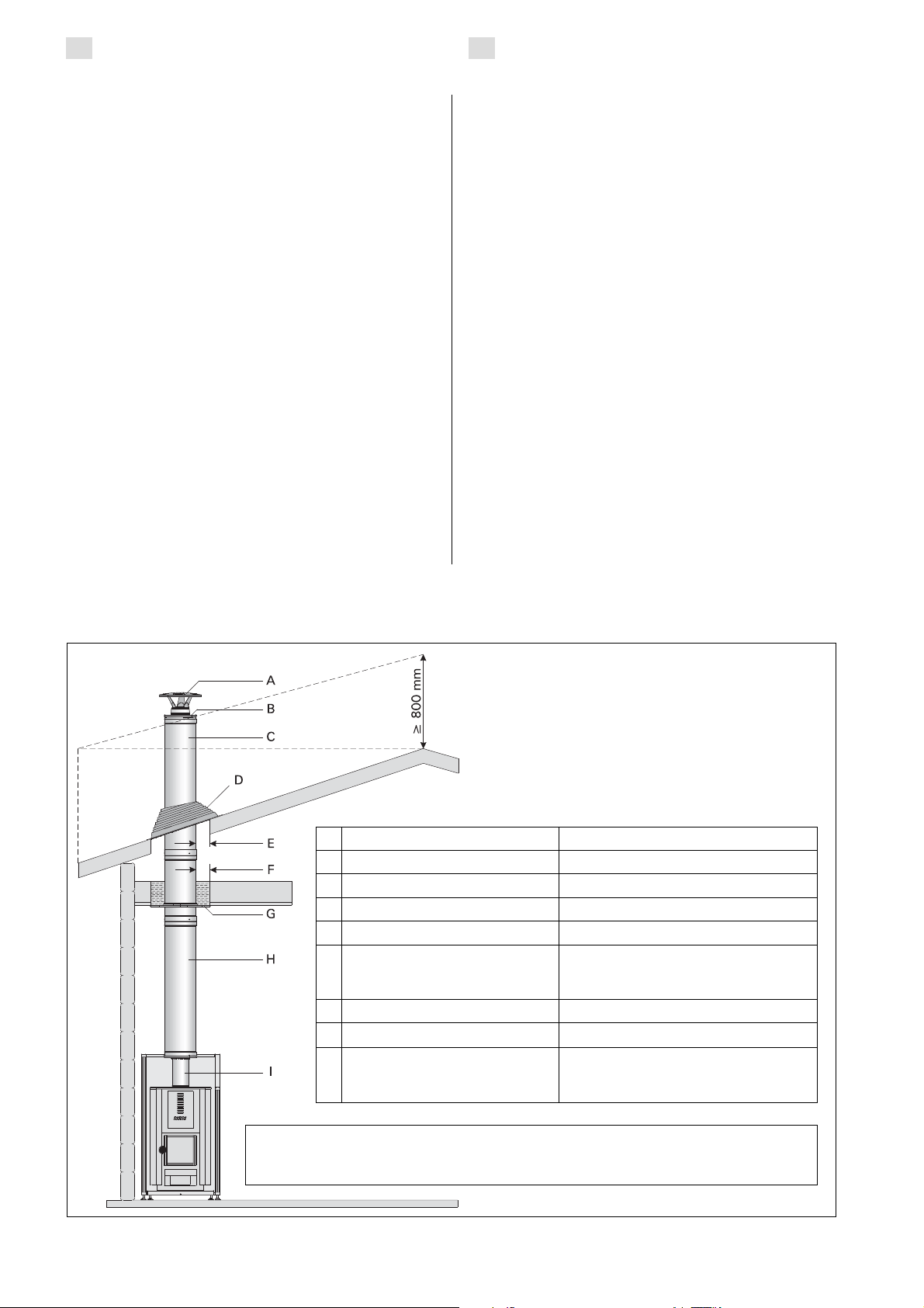
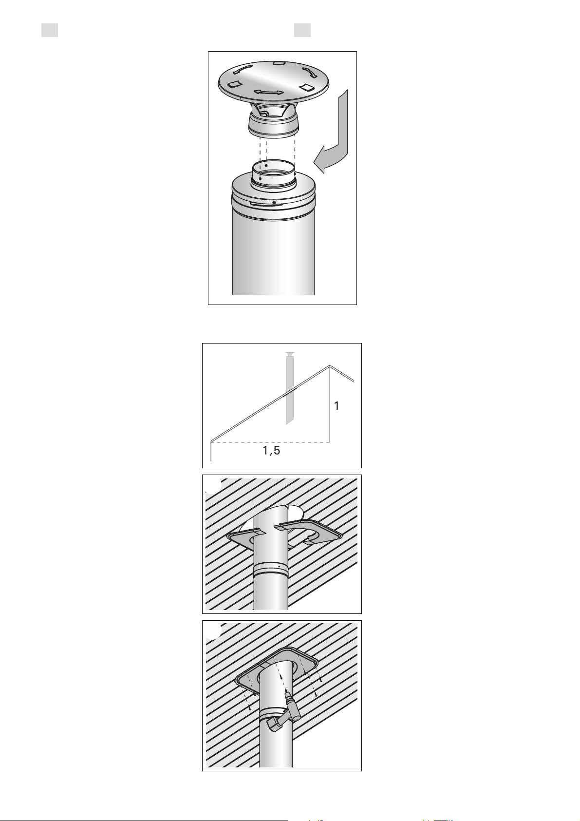
Figure 2. Examples of chimney heights required for fire safety regulations.
Ðèñóíîê 2. Ïðèìåðû òðåáîâàíèé ïîæàðíîé áåçîïàñíîñòè ê âûñîòå äûìîõîäà.
2. Protective distances
The protective distance between the inflammable
structures and the chimney outer casing must be
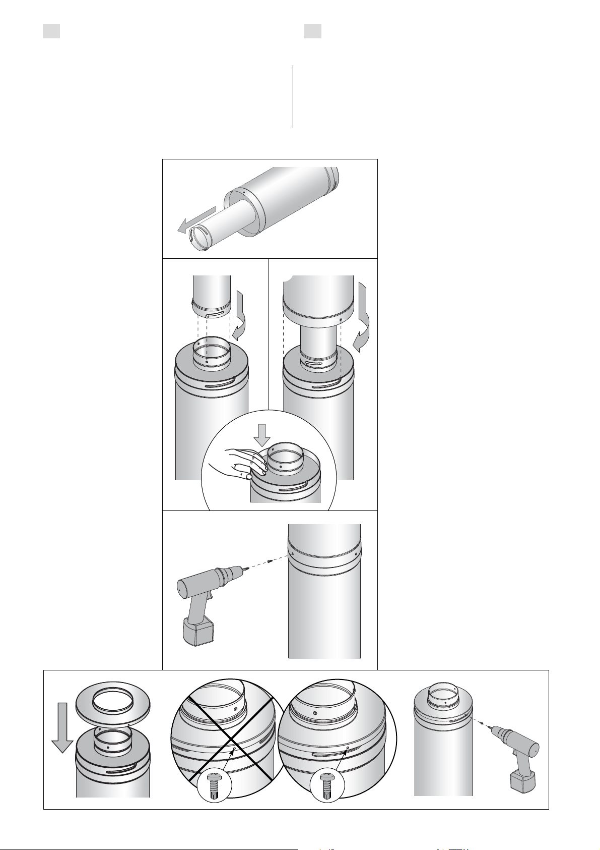
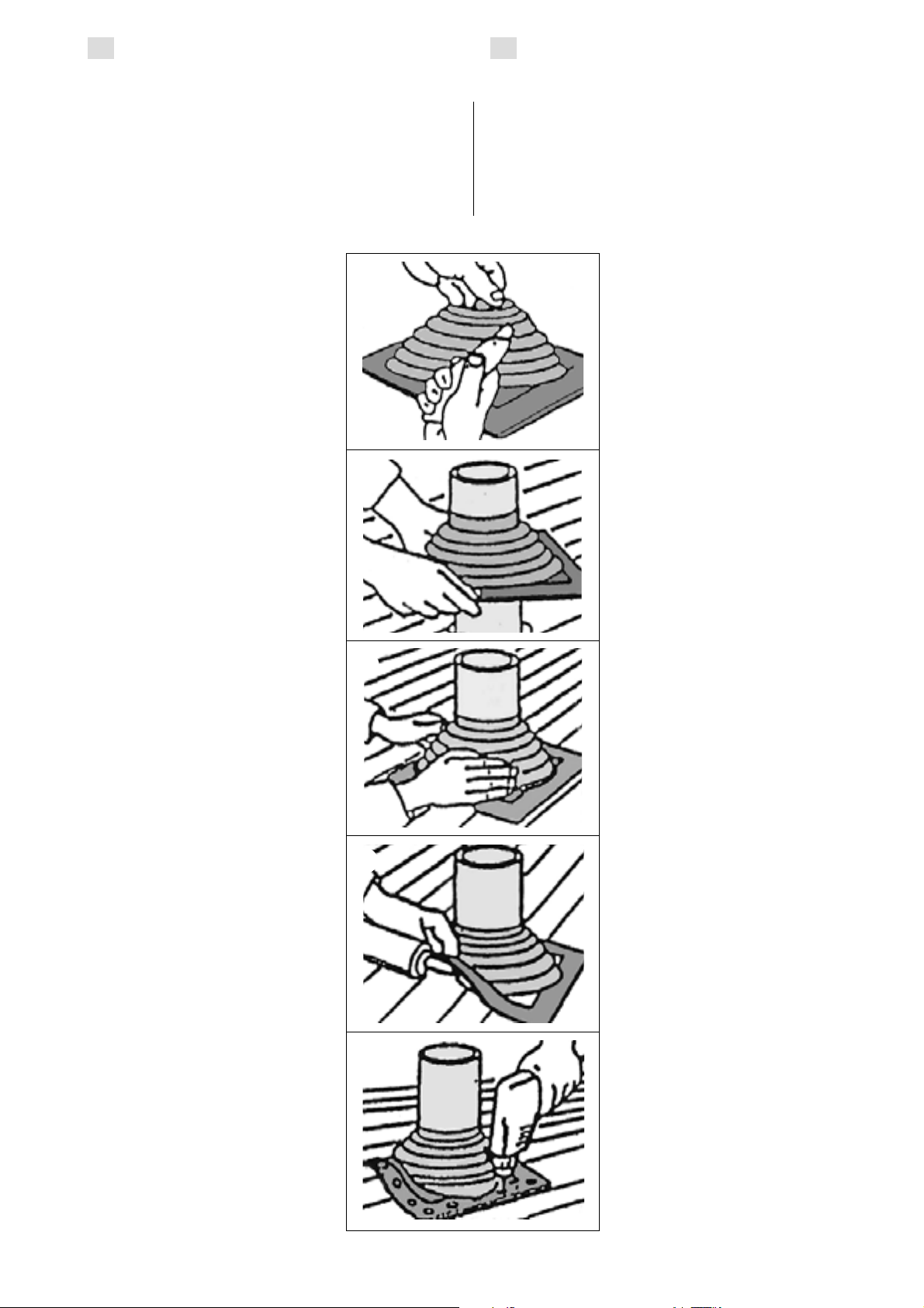
minimum 100 mm. In lead-through the chimney
and the roof structures have to be filled with fire-
resistance rated mineral wool. If the connecting
pipe in the forward end is of non-isolated
material, the protective distance from this pipe
to inflammable construction materials needs to
be 1000 mm. Furthermore, the isolated chimney
should be visible up to a minimum
of 430 mm (figure 3).
If the chimney is connected to a
sauna stove equipped with a pipe-
model water tank, the bare part of
the smoke pipe must be equipped
with a radiation cover (figure 4).
The water tank installation should
follow the protective distances
from the mounting instructions.
In case the protective distance
requirements for the furnace
are higher than for the chimney
the distance can be reduced
by installing non-flammable
protective plates. The protective
distance requirements are
specified in the installation
manual. A single flange halves the
protective distance and a double
flange to a quarter. Either a 7.0
mm non-flammable wallboard or a
minimum 1.0 mm metal sheet can
be used for such light protection.
The board or sheet gap from the
protected, inflammable material
must be minimum 30 mm and
the air circulation secured in
the gap through the lower and
upper end of the protecting
construction. If a double flange
protective plate is used, a 30 mm
gap should be constructed using
bushing manufactured out of non-
flammable materials allowing free
air circulation through the upper
and lower end of the plates.
More detailed instructions
available from the local fire
authorities.
2. Áåçîïàñíîå ðàññòîÿíèå
Áåçîïàñíîå ðàññòîÿíèå ìåæäó âîñïëàìåíÿþùèìèñÿ
êîíñòðóêöèÿìè è âíåøíåé ñòàëüíîé ðóáàøêîé
äûìîõîäà äîëæíî ñîñòàâëÿòü íå ìåíåå 100 ìì. Ïðè
ïðîâåäåíèè ïðîõîäà ðàññòîÿíèå ìåæäó äûìîõîäîì
è êîíñòðóêöèÿìè êðûøè äîëæíî áûòü çàïîëíåíî
îãíåñòîéêîé ìèíåðàëüíîé âàòîé. Åñëè â íà÷àëüíîé
÷àñòè äûìîõîäà áûëà èñïîëüçîâàíà ïðîìåæóòî÷íàÿ
òðóáà áåç èçîëÿöèè, áåçîïàñíîå ðàññòîÿíèå ìåæäó
äàííûì ó÷àñòêîì äûìîõîäà è âîñïëàìåíÿþùèìèñÿ
êîíñòðóêöèÿìè, ñîãëàñíî òðåáîâàíèÿì
ïîæàðíîé áåçîïàñíîñòè, âîçðàñòàåò äî 1000
ìì. Íåîáõîäèìî ó÷èòûâàòü, ÷òî â ïîìåùåíèè
ó÷àñòîê âèäèìîé èçîëèðîâàííîé òðóáû
äîëæåí ñîñòàâëÿòü íå ìåíåå 430 ìì (ðèñ. 3).
Åñëè äûìîõîä ïîäñîåäèíÿåòñÿ ê êàìåíêå,
îñíàùåííîé âîäîíàãðåâàòåëåì òðóáíîãî
òèïà, òî íåèçîëèðîâàííóþ ÷àñòü âíóòðåííåé
òðóáû íåîáõîäèìî çàùèòèòü ýêðàíîì
òåïëîâîãî èçëó÷åíèÿ (ðèñ. 4). Ïðè ìîíòàæå
ðåçåðâóàðà äëÿ âîäû íåîáõîäèìî ó÷èòûâàòü
òðåáîâàíèÿ ê áåçîïàñíûì ðàññòîÿíèÿì.
Åñëè òðåáîâàíèÿ ê áåçîïàñíîìó ðàññòîÿíèþ
òîïêè âûøå, ÷åì ó äûìîõîäà, òî áåçîïàñíîå
ðàññòîÿíèå ìîæíî óìåíüøèòü ñ ïîìîùüþ
çàùèòíîé ïëàñòèíû, èçãîòîâëåííîé èç
íåãîðþ÷èõ ìàòåðèàëîâ. Òðåáîâàíèÿ ê
áåçîïàñíûì ðàññòîÿíèÿì òîïêè óêàçàíû
â èíñòðóêöèè ïî åå ìîíòàæó. Îäèíàðíàÿ
çàùèòà ñîêðàùàåò áåçîïàñíîå ðàññòîÿíèå
âïîëîâèíó, à äâîéíàÿ çàùèòà – äî îäíîé
÷åòâåðòîé ÷àñòè. Îäèíàðíóþ çàùèòó ìîæíî
èçãîòîâèòü èç íåãîðþ÷åãî ñòðîèòåëüíîãî
ëèñòà, ïîäõîäÿùåãî äëÿ ýòèõ öåëåé,
òîëùèíîé íå ìåíåå 7,0 ìì è ìåòàëëè÷åñêîãî
ëèñòà òîëùèíîé íå ìåíåå 1,0 ìì. Ìåæäó
âîñïëàìåíÿþùèìñÿ ìàòåðèàëîì è çàùèòíûì
ýëåìåíòîì íåîáõîäèìî îñòàâèòü çàçîð íå
ìåíåå 30 ìì, îáåñïå÷èâàþùèé ñâîáîäíóþ
öèðêóëÿöèþ âîçäóõà ìåæäó âåðõíèìè è
íèæíèìè ïëàñòèíàìè çàùèòíîãî ýëåìåíòà.
Ïðè èñïîëüçîâàíèè äâóõñëîéíîé çàùèòû
ìåæäó ëèñòàìè íåîáõîäèìî, ñ ïîìîùüþ,
íàïðèìåð, ðàñïîðíûõ âòóëîê èç íåãîðþ÷åãî
ìàòåðèàëà, îñòàâèòü çàçîð íå ìåíåå 30 ìì,
îáåñïå÷èâàþùèé ñâîáîäíóþ öèðêóëÿöèþ
âîçäóõà ìåæäó îáåèìè ïëàñòèíàìè çàùèòíîãî
ýëåìåíòà.
Çà áîëåå ïîäðîáíûìè èíñòðóêöèÿìè ìîæíî
îáðàòèòüñÿ â ìåñòíûå îðãàíû ïîæàðíîé
áåçîïàñíîñòè.
Radiation cover
Çàùèòà îò òåïëîâîãî
èçëó÷åíèÿ
Figure 3.
Ðèñóíîê 3.
min. 430 mm
ìèí. 430 ìì

6
EN RU
Ýëåìåíòû äûìîõîäà ñîåäèíÿþòñÿ ìåæäó ñîáîé ñïîñîáîì,
óêàçàííûì íà ñåðèè ðèñóíêîâ. Ïðåäâàðèòåëüíî ñ
îñíîâíîãî ìîäóëÿ ñíèìàåòñÿ âåðõíèé òîðöîâûé ýëåìåíò,
êîòîðûé â êîíöå ìîíòàæà óñòàíàâëèâàåòñÿ íà âåðõíèé
äîïîëíèòåëüíûé ìîäóëü. Ìîíòàæ îñóùåñòâëÿåòñÿ
ñëåäóþùèì îáðàçîì: âíóòðåííÿÿ ÷àñòü äûìîõîäà
ïðèêðó÷èâàåòñÿ ê ïðåäûäóùåìó ýëåìåíòó, çàòåì íà íåå
óñòàíàâëèâàåòñÿ è ïðèæèìàåòñÿ âíåøíÿÿ ðóáàøêà ñ
èçîëÿöèîííûì ìàòåðèàëîì, è â êîíöå
âíåøíÿÿ ðóáàøêà çàêðåïëÿåòñÿ ñ
ïîìîùüþ øóðóïîâ.
A. Âíóòðåííÿÿ ÷àñòü ïðèñîåäèíÿåìîãî
ìîäóëÿ èçâëåêàåòñÿ èç èçîëÿöèîííîãî
ñëîÿ è âíåøíåé ðóáàøêè.
B. Ïàçû ñîåäèíÿåìîé âíóòðåííåé
òðóáû ïîäãîíÿþòñÿ ïîä øèïû
âíóòðåííåé ÷àñòè, íàõîäÿùåéñÿ âíèçó.
Ýëåìåíò ïðîêðó÷èâàåòñÿ ïî ÷àñîâîé
ñòðåëêå äî ïîëíîãî çàòÿãèâàíèÿ ìåñòà
ñîåäèíåíèÿ è äî ïîëíîé îñòàíîâêè.
C. Âíåøíÿÿ ðóáàøêà ñ èçîëÿöèîííûì
ìàòåðèàëîì óñòàíàâëèâàþòñÿ íà
âíóòðåííþþ ÷àñòü. Ïàçû ñîåäèíÿåìîé
âíåøíåé ðóáàøêè ïîäãîíÿþòñÿ ïîä
øèïû âíåøíåé ðóáàøêè, íàõîäÿùåéñÿ
âíèçó. Ýëåìåíò ïðîêðó÷èâàåòñÿ
ïî ÷àñîâîé ñòðåëêå äî ïîëíîãî
çàòÿãèâàíèÿ ìåñòà ñîåäèíåíèÿ è äî
ïîëíîé îñòàíîâêè.
D. Äëÿ óïëîòíåíèÿ âîçìîæíûõ çàçîðîâ
ìåæäó ñëîÿìè èçîëÿöèè ðàçíûõ
ýëåìåíòîâ íà èçîëÿöèîííûé ìàòåðèàë
íåîáõîäèìî íàäàâèòü ñâåðõó.
E. Âíåøíÿÿ ðóáàøêà çàêðåïëÿåòñÿ
òðåìÿ øóðóïàìè-ñàìîðåçàìè.
Øóðóïû óñòàíàâëèâàþòñÿ â ðóáàøêó â
ìåñòå óãëóáëåíèé.
F. Âåðõíèé òîðöîâûé ýëåìåíò
çàêðåïëÿåòñÿ òðåìÿ øóðóïàìè-
ñàìîðåçàìè. Øóðóïû ïðîõîäÿò ñêâîçü
ðóáàøêó.
ÂÍÈÌÀÍÈÅ! Âåðõíèé òîðöîâûé
ýëåìåíò äîëæåí áûòü óñòàíîâëåí
òàêèì îáðàçîì, ÷òîáû øóðóïû
ïîïàëè â ðåáðî æåñòêîñòè,
îáðàçóåìîå ïàçàìè âåðõíåé
ðóáàøêè.
A. Pull the smoke pipe
of the component/
extension out of the
insulation and the outer
casing.
B. Join the pipe by
slotting it to the studs
of the smoke pipe
below. Turn clockwise
until the joint tightens
and the pipe is fixed.
C. Press the outer
casing with the
insulation on the smoke
pipe. Slot the studs in
the outer casing below.
Turn clockwise until the
joint tightens and the
pipe is fixed.
D. Any gaps between
the insulation sheets
should be sealed
by pressing them
downwards in the pipe.
E. Lock the outer casing
in place with three self-
boring screws. Bore
the screws through the
metal sockets.
F. Join the upper end
with three self-boring
screws. Bore the
screws through the
plate.
NOTE! The upper end
should be installed in
a position where the
screws will meet with
the slot-braced outer
casing.
3. Connecting the parts of the Steel Chimney
The components of the steel chimney are joined
by following the instructions in the pictures. The
leading principle is to lock the smoke pipe to the
former component by winding it in place, then
pressing the outer casing with insulation on the
smoke pipe and finally locking the casing in place
with screws.
F
A
B
E
C
D
3. Ñîåäèíåíèå ýëåìåíòîâ äûìîõîäà ìåæäó ñîáîé

7
EN RU
4. Installing the rain flange
The rubber rain flange prevents water and snow
entering through the chimney lead-through hole.
If the profile of the roofing material is very high
or brick is used, an integral, uniform and stiffened
metal sheet covering the chimney hole should be
installed. This ensures the flange is fixed firmly in
the damper.
A. Cut an opening in the rain
flange with the diameter of 175-
180 mm i.e. approx. 20 % less
than the chimney diameter.
B. Mount the flange from the
upper end of the chimney on
the surface of the roof. Soap
solution can be used as a
lubricant if needed.
C. Mould the brims of the rain
flange carefully fitting it to the
roof profile.
D. Spread some silicone
underneath the flange and press
the flange into place on the roof
covering. Smooth out the excess
silicone against the edge of the
rain flange.
E. Fix the flange to the damper
with screws. The recommended
spacing is max. 35 mm. Finally
check that there are no gaps in
the sealing.
NOTE! A special snow barrier is
needed to prevent snow from
sliding against the rain flange. The
amassed snow should be removed
occasionally thus preventing the
snow accumulating and clumping
on the flange.
A
E
B
C
D
Äîæäåâîé ôëàíåö èç ðåçèíû ïðåïÿòñòâóåò
ïðîíèêíîâåíèþ äîæäåâîé âîäû è ñíåãà ñêâîçü ïðîõîä
äûìîõîäà. Åñëè êðîâåëüíîå ïîêðûòèå èìååò âûñîêèé
ïðîôèëü, ëèáî â êà÷åñòâå êðîâåëüíîãî ìàòåðèàëà
èñïîëüçîâàíà ÷åðåïèöà, â òàêîì ñëó÷àå ñ êîíüêà êðûøè
íåîáõîäèìî óñòàíîâèòü ðîâíûé ëèñò æåñòêîé æåñòè,
çàõîäÿùèé çà îòâåðñòèå äûìîõîäà. Ýòî ïîçâîëèò
ïðî÷íî çàêðåïèòü äîæäåâîé ôëàíåö íà îñíîâàíèè.
A. Â îòâåðñòèè äîæäåâîãî ôëàíöà
ïðîðåçàåòñÿ îòâåðñòèå äèàìåòðîì
îêîëî 175-180 ìì, òî åñòü
ïðèìåðíî íà 20 % ìåíüøå äèàìåòðà
äûìîõîäà.
B. Äîæäåâîé ôëàíåö ïðîòÿãèâàåòñÿ
ñêâîçü îòâåðñòèå ïî òðóáå äûìîõîäà
è ïðèæèìàåòñÿ ê ïîâåðõíîñòè
êðûøè. Äëÿ óìåíüøåíèÿ òðåíèÿ ïðè
ïðîòÿãèâàíèè ìîæíî èñïîëüçîâàòü,
íàïðèìåð, ìûëüíûé ðàñòâîð.
C. Êðàÿ äîæäåâîãî ôëàíöà
òùàòåëüíî ïîäãîíÿþòñÿ ïîä
ïðîôèëü êðîâëè.
D. Íà íèæíþþ ÷àñòü äîæäåâîãî
ôëàíöà íàíîñèòñÿ ñèëèêîí, è
ôëàíåö ïëîòíî ïðèæèìàåòñÿ
íà ìåñòî, ê ïîâåðõíîñòè êðîâëè.
Ëèøíèé ñèëèêîí, âûäàâëåííûé
èç-ïîä ôëàíöà, ðàçðàâíèâàåòñÿ ïî
êðàþ.
E. Ôëàíåö êðåïèòñÿ øóðóïàìè ê
îñíîâàíèþ. Ðåêîìåíäóåìûé øàã
ìåæäó øóðóïàìè íå ïðåâûøàåò 35
ìì. Íå çàáóäüòå ïðîâåðèòü, ÷òî â
óïëîòíèòåëå íå îñòàëîñü ùåëåé.
ÂÍÈÌÀÍÈÅ! Äîæäåâîé ôëàíåö
íåîáõîäèìîçàùèòèòüñíåãîâûì
áàðüåðîì îò ñêîïëåíèé ñíåãà.
Åñëè çèìà îñîáåííî ñíåæíàÿ,
ðåêîìåíäóåòñÿ óäàëÿòü âðåìÿ
îò âðåìåíè ñíåã îò îñíîâàíèÿ
äûìîõîäà, íå äîïóñêàÿ åãî
ñêîïëåíèÿ íà äîæäåâîì
ôëàíöå.
4. Óñòàíîâêà äîæäåâîãî ôëàíöà

8
EN RU
5. Installing the rain cap
Slot in the damper with the smoke
pipe of the lower module. Lock the
rain cap in place by gently turning
it clockwise.
NOTE! Be careful not to turn and
lock the rain cap too tight! The cap
needs to be removed for chimney
sweeping.
6. Installing the lead-through flange
The two-piece lead-through
flange fixed in horizontal or
pitched ceilings trims the edges
of the opening. The lead-through
flange is best suited for roof
pitches of under 1:1.5.
A. Install the two halves of the
flange around the chimney. The
straighter the roof, the more the
components will overlap.
B. Fix the lead-through flange
in place with screws. Be careful
and tighten the screws only so
much as not to bend the metal
sheet.
5. Óñòàíîâêà îãîëîâêà äûìîõîäà
6. Óñòàíîâêà ïðîõîäíîãî ôëàíöà
Ïàçû îãîëîâêà äûìîõîäà ïîäãîíÿþòñÿ
ïîä øèïû âíóòðåííåé ÷àñòè ýëåìåíòà,
íàõîäÿùåãîñÿ âíèçó. Îãîëîâîê
äûìîõîäà çàêðåïëÿåòñÿ ëåãêèì
ïîâîðîòîì ïî ÷àñîâîé ñòðåëêå.
ÂÍÈÌÀÍÈÅ! Íå ðåêîìåíäóåòñÿ
çàòÿãèâàòü îãîëîâîê äûìîõîäà
ñëèøêîì ïëîòíî. Åãî íåîáõîäèìî
óäàëÿòü âî âðåìÿ ïðî÷èñòêè
òðóáû äûìîõîäà.
Ñîñòîÿùèé èç 2-õ ÷àñòåé ïðîõîäíîé
ôëàíåö, óñòàíàâëèâàåìûé íà
ãîðèçîíòàëüíûõ è íàêëîííûõ
ïîòîëêàõ, ïðèäàåò àêêóðàòíûé âèä
êðàÿì îòâåðñòèÿ.Ïðîõîäíîé ôëàíåö
ëó÷øå âñåãî ïîäõîäèò äëÿ êðîâåëü ñ
íàêëîíîì 1:1,5.
A. Ïîëîâèíêè ôëàíöà
óñòàíàâëèâàþòñÿ âîêðóã òðóáû
äûìîõîäà. ×åì ìåíüøå íàêëîí
ñêàòà, òåì áîëüøå íàëîæåíèå
äåòàëåé ïðîõîäíîãî ôëàíöà.
B. Ïðîõîäíîé ôëàíåö êðåïèòñÿ
ïî ìåñòó íà øóðóïàõ. Øóðóïû
ðåêîìåíäóåòñÿ çàòÿãèâàòü
îñòîðîæíî, ÷òîáû èçáåæàòü
ïîâðåæäåíèÿ æåñòè ôëàíöà.
A
B
Other manuals for WHP1500
3
Table of contents
Other Harvia Ventilation Hood manuals
Popular Ventilation Hood manuals by other brands

KitchenAid
KitchenAid KICU265HBT0 parts list

Cata
Cata ASOMA 600 Installation, use and maintenance instructions

GeekChef
GeekChef GBI-F30A user manual

ELICA
ELICA Space EDS Instruction on mounting and use

Trade-wind
Trade-wind 7236 Installation instructions & use & care guide

GE
GE Monogram ZV1050 owner's manual

Zanussi
Zanussi ZHC 600 Installation, use and maintenance handbook

Zanussi
Zanussi ZFVX19K user manual

Viking
Viking BVWH83678SS manual

Blanco
Blanco BRCS9810X Instructions for Use and Care and Installation

Zephyr
Zephyr Brisas BMI-E36AG Use, care and installation guide

Bellini
Bellini BDRA603TBX Installation & operation instructions