SECTION II. – INSTALLATION PROCEDURE
This equipment shall be installed and wired in accordance with regulations of the National
Board of Fire Underwriters, National Electric Code, Gas Burning Appliance and Equipment,
CGA B.149.1 & 2, applicable Provincial Regulations for the class, and local governing bodies
which should be carefully followed in all cases. The following recommendations are not
intended to supplant any requirements of federal, state, or local codes having jurisdiction.
Authorities having jurisdiction should be consulted before installations are made. Local codes
may require additional safety controls and/or interlocks.
The installer must identify the emergency shut-off devices after completion of the installation.
A. HANDLING THE EQUIPMENT
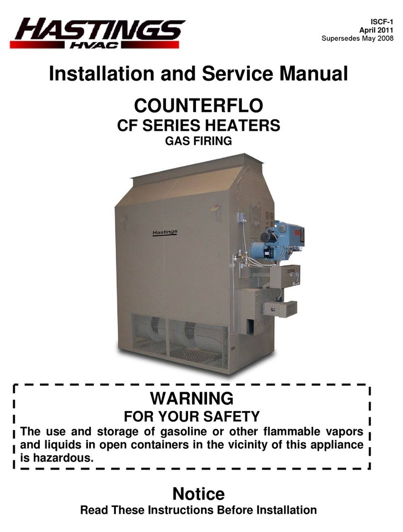
The Counterflo heater has been designed for rigging and handling through the use of special
lifting lug hooks installed on the sides of the unit. As explained previously, the standard unit is
designed for shipping in one piece. Optional accessories must be field mounted. Figure 1
depicts a typical Counterflo heater for vertical floor mounting.
When unloading and setting the heater, use the lifting lugs provided or move the heater on
rollers. Hooks, jacks, or chains must not be used around the casing, exhaust fan, or main
control panel – DO NOT LIFT UNIT USING COMBUSTION CHAMBER BRACKETS.
To be properly set, the Counterflo heater should be placed on a solid foundation and set
exactly as detailed later.
During transit, unloading, and setting of the unit, bolts and nuts may have become loosened,
particularly in the pillow block ball bearing assemblies in the fan section. It is recommended
that all nuts and set screws be tightened. Turn fan shaft by hand to make certain that blower
does not rub against blower housing, and that bearing lock rings are tight.
Open the cover on the electrical control box located near the middle on the side of the burner
section. Box can be opened by turning main disconnect switch to the “off” position. Inspect all
wire terminals and wiring terminations to ensure that all connections are tight.
B. POSITIONING THE HEATER
Locate the heater exactly level, making certain the minimum clearance is maintained between
the heater, and any unprotected combustible material. The clearances are: 48” from main
control panel located at the burner end, 18” at the rear, both sides and top. The exhaust stack
clearance must be 18”. See page 9 for stack details. Units must be installed on non-
combustible flooring.
For convenient access for maintenance, provide 24” clearance at the right side, as seen when
facing the burner, and 36” at the rear. Position the heater, if practical, with the left hand side
(as seen from burner end) next to any adjacent wall.
Special attention should be given to the exhaust duct connections, electrical power and control
hookup points, and fuel connection points. This information should be cross-checked with the
position of support beams and stand pipes to insure that clearance dimensions coincide with
those of the unit.
-3-

