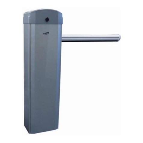
HATO 535Y User manual

HATO 535Y
AUTOMATIC BARRIER
OPERATING MANUAL

Spis treści
RECOMMENDATIONS AND PRECAUTIONS...............................................................3
DECLARATION OF CONFORMITY..............................................................................4
BARRIER..................................................................................................................4
SPECIFIACTION........................................................................................................4
LIST OF ELEMENTS...................................................................................................5
DIMENSIONS...........................................................................................................5
ASSEMBLY AND ADJUSTMENT.................................................................................
E HELB11SZ ELECTRONICS......................................................................................11
SAFETY RECOMMENDATIONS................................................................................12
DEVICE DESCRIPTION.............................................................................................13
SPECIFICATION (electronics)..................................................................................14
DIMENSIONS.........................................................................................................14
DRIVER ASSEMBLY.................................................................................................15
CONNECTION DIAGRAM........................................................................................18
SETTINGS PROGRAMMING....................................................................................19
1.WARRANTY CONDITIONS....................................................................................24
Congratulations on your purchase of HATO 535Y automatic barrier and welcome to the
users of HATO products. Declarations of conformity and manuals for HATO TRADE SP. ZOO
products can be downloaded from our website: http://www.hato.com.pl
Before assembling and using the barrier for the first time, read the manual carefully and

eep them for future reference.
In accordance with the provisions of the Machinery Directive 2006/42 / WE, it is declared
that the product may not be put into operation until the final machine, into which it is built or a
subassembly of which it is built, obtains a declaration of compliance with the directives and
relevant regulations, which the final machine must meet.
RECOMMENDATIONS AND PRECAUTIONS
Before installing and using the drive, carefully read all warnings and safety rules. Incorrect
installation and non-compliance with the standards contained in the manual may result in serious
accidents.
All installation wor should be carried out in accordance with applicable regulations and
standards.
The driver installation may only be performed by qualified and authorized personnel.
Installation should be carried out with basic ESD protection.
Be especially careful during assembly! The controller uses 230Vac voltage (life and health
threatening).
All wor s related to the proper functioning of the device (connection, start-up, operation)
must be carried out in accordance with the applicable regulations in the field of electrical
equipment operation and in accordance with health and safety regulations.
Do not connect the drive to the power supply earlier than specified in the manual, failure
to do so may result in electric shoc .
Before starting the installation, chec the mechanical condition of the barrier: it should not
sway excessively, it should move easily and smoothly.
Before installation, remove unnecessary items and secure accessories, such as loc s.
During assembly, children, handicapped persons and motor vehicles must not be in the
vicinity of the barrier.
All fixed control elements should be located near the barrier, but away from moving parts
and out of the reach of outsiders.
Before repairing or removing any parts of the barrier, disconnect power.
Children and people with intellectual disabilities cannot control the barrier on their own.
Configuration of overload and thrust settings may only be performed by qualified
personnel.
Fluorescent lamps must not be used as traffic lights.
AUTOMATIC BARRIER IS NOT
INTENDED FOR PEDESTRIAN TRAFFIC
This product may only be used for its intended purpose. Improper use is improper and
dangerous. The manufacturer of the product is not liable for any damage caused by improper or
negligent use.

Failure to follow the instructions above may result in serious
injury or equipment damage. The manufacturer is not liable for
damage and malfunctions resulting from failure to observe these
installation and operating instructions.
In accordance with the regulations in force on the disposal of
waste equipment by private users in the European Union, items
bearing this symbol MUST NOT be disposed of with other rubbish. In
this case, the user is responsible for proper disposal by delivering the
device to a designated point, or to the manufacturer who will ta e
care of its further disposal. Separate collection and recycling of
unnecessary devices helps to protect the environment and ensures
that disposal is done in a way that protects human health and the
environment. This note also applies to waste batteries and
accumulators.
DECLARATION OF CONFORMITY
The HATO 535Y automatic barrier meets the requirements set out in the following regulations:
Complies with the conditions of the Machinery Directive 2006/42 / EC Annex II Section B as
amended.
Complies with the conditions of the following EU directives:
Directive on electromagnetic compatibility EMC 2014/30 / EU
Low Voltage Directive LVD 2014/35 / EU
The following harmonized standards have been applied:
EN60335-1: 2012, EN 60335-2-103: 2015-3, EN 55014-1: 2012,
EN 55014-2: 2015-06,
EN 61000-3-2-2014-10, EN 61000-3-3: 2013-10
the current declaration can be downloaded from the manufacturer's website www.hato.com.pl
BARRIER
SPECIFIACTION

Model HATO 535Y
Power supply 220×(1±10%)V 50Hz
Engine power 180W
Lowering/lifting time 3.5s
Wor ing range of time 30m
Noise ≤62dB
Operating temperaturę -20ºC~+45ºC
Dimensions 360﹡230﹡1050
Max. arm length 5m
Weight 60 g
Number of cycles per hour 200
LIST OF ELEMENTS
No
.
Description Quantity
1 Barrier 1
2 Mounting plate for the barrier arm 1
3 Barrier mounting cover 1
4 Handle 1
5 Remote control 1
6 M12 dowel pin 4
7 M10 x 16 the bolt securing the barrier 4
8 M4 x 5 cover fixing bolt 3
9 M12 washer 4
10 Key 2
11 Manual 1
DIMENSIONS


The LEFT barrier is shown in the diagram above.
ASSEMBLY AND ADJUSTMENT
REQUIRED TOOLS:
- set of eys
- set of screwdrivers
- drill
CORDS:
- power cord 1,5mm2
- signal cord 0,5mm2
FOUNDATION:
When the foundation is poured under the barrier, a PVC pipe should be placed in it (min. 12mm
diameter). This way we can secure the cords brought to the barrier in front of the mechanical
device. Diagram above. Power and signal cord should always be separated.

BARRIER (fastening):
Four M12 fixing bolts can be inserted into the foundation during pouring or alternatively you can drill holes in the
foundation and use expansion plugs (supplied).
Hole spacing: 150mm x 260mm. To do this, place the barrier on the foundation and mar the holes. Then move the
barrier and drill the holes. Put expansion plugs into the drilled holes or instert the screws into the still wet concrete.
Place barrier over the bolts and tighten using the washers and nuts provided.
BARRIER ARM:
Fit the barrier arm to the barrier and fasten it with four M10x16 screws.

Then mount the barrier cover with three M4x5 screws.
EMERGENCY OPENING:
In case of a power failure, use the handle to manually open or close the barrier.
Before starting manual operation of the barrier, it is necessary to:
- disconnect the power supply to avoid accidental activation of the barrier.
- put the handle in the designated place, covered with a plastic cover.
- turn the handle in the appropriate direction to open or close.
- pull out the handle before turning on the power
LIMIT SWITCH (normally open)
Regulowane wyłączni i rańcowe służą do zatrzymania szlabanu w pozycji otwartej lub zam niętej.
INITIAL ADJUSTMENT
- Use the handle to manually set the barrier in the opening position. Loosen the M4 screw of the opening cam and
turn the cam until the green indicator light for limit switch open comes on, then tighten the M4 screw.
- Use the handle to manually set the barrier to the closed position. Loosen the M4 screw of the closing cam and turn
the cam until the red indicator light for limit switch closed is on, then tighten the M4 screw.
FINAL ADJUSTMENT
- After adjusting the cams of the limit switch, activate the barrier and chec that the pre-adjustment of the position is
correct. In a situation when the end positions deviate from the desired ones, already on the attached barrier, it is
necessary to precisely adjust the limit switches.
SPRING BALANCING:

Correct adjustment of the balancing spring is crucial for the proper operation of the barrier. The barrier is
adjusted in the open position, when the balance spring is loose.
Dźwignia napędu posiada cztery otwory Ø15, szlaban oryginalnie dostarczany jest z sprężyna balansującą
zamontowaną w pierwszym otworze (5-6m), w sytuacji gdy szlaban jest rótszy niż 5m., należy zamontować
sprężynę w odpowiedni otwór.
To do this you need to;
• Loosen the spring, bringing the barrier to the open position.
• Loosen the nut and the turnbuc le (turn cloc wise)
• Pull out the cotter pin and disassemble the spring mount to the drive lever.
• Select the appropriate hole corresponding to the length of the barrier, install the spring mount and the
cotter pin.
• Final adjustment is done with a turnbuc le.
• Tighten the nut

E HELB11SZ ELECTRONICS
SIMPLIFIED EU DECLARATION OF CONFORMITY
PRODUCENT/HEREBY,
HATO TRADE SP. ZOO
Żeromskiego 1, 41-205 Sosnowiec
hereby declares that the device type HELB11SZ complies with the directives:
EMC 2014 30 UE, LVD 2014 35 UE, RED 2014 53 UE, ROHS 2011 65 UE, MD 2006 42 UE
declares that the equipment type HELB11 is in compliance with Directives:
EMC 2014 30 UE, LVD 2014 35 UE, RED 2014 53 UE, ROHS 2011 65 UE, MD 2006 42 UE
The full text of the EU declaration of conformity is available at the following internet address:
hato.com.pl

SAFETY RECOMMENDATIONS
Before assembling and using the controller for the first time, read the manual carefully
and keep it for future reference.
MARKING OF THE SYMBOLS
IMPORTANT SAFETY INSTRUCTIONS!
INFORMATION!
In accordance with the applicable European regulations, the
motorized gate must be made in accordance with the Directive
2006/42 / EC. It must also meet, inter alia, standard requirements: EN
13241-1; EN 12445; EN 12453 and EN 12635.
In accordance with the provisions of the Machinery Directive 2006/42 / EC, it is declared
that the product may not be put into operation until the final machine, into which it is built or a
subassembly of which it is built, obtains a declaration of compliance with the directives and
relevant regulations, which the final machine must meet.
GENERAL RECOMMENDATIONS
The installer, maintenance person and all users of the drive must read the Assembly and Operating
Manual.
Keep this installation and operating manual in an accessible place.
Use the product in accordance with its intended use.
Observe and comply with the health and safety regulations and standards in force in the respective
countries.
Installation, connection, and initial start-up of the drive may only be performed by qualified
personnel.
Only install the drive in correctly fitted gates.
Before carrying out any wor on the drive, disconnect the power supply and secure it against being
switched on accidentally. This also applies to battery operation.
During any welding wor close to the gate, disconnect the gate from the power supply and
disconnect the electronic circuits.
The methods of electrical installation as well as its protection against electric shoc are defined by
the applicable standards and legal regulations.
Install the safety devices (photocells, safety edges, etc.).
Install a warning sign - Gate in automatic movement on the gate.
The manufacturer is not liable for any damage and malfunctions resulting from failure to comply
with these installation and operating instructions.

Follow all installation instructions. Incorrect assembly can lead
to serious personal injury.
EXPLOITATION
Only use the drive if it is installed in accordance with applicable standards and guarantees the user's
safety.
The barrier may only be used by trained personnel.
Children and mentally disabled persons cannot control the drive.
Do not put your hands or other body parts into the moving barrier or its moving parts.
Do not put any objects or mechanical elements into the moving barrier or its moving parts.
Only drive through the gate when it is fully opened.
In the event of automatic closing of the barrier, the edges and the entire wor ing space must be
secured in accordance with the applicable standards.
When the gate is moving, there must be no children, adults, animals or any objects in its wor area.
Regularly chec the operation of safety elements.
Defects that may affect safe use must be repaired immediately.
The distance between the end of the arm and the nearest object should be more than 0.5 m.
Under no circumstances should the device be used without the arm or spring fitted.
For safety, remove cran before reconnecting the power to the machine.
Use the drive in a non-explosive atmosphere.
Fluorescent lamps must not be used as traffic lights.
Do not use the drive in a room with an aggressive atmosphere.
Carry out inspection and maintenance wor at least every 6 months.
INSTALLATION
Gates (barriers) that are automatically opened with a drive must meet the requirements of
applicable standards and directives.
Use only a technically efficient drive, in accordance with its intended purpose, ta ing into account
the safety and hazard rules and observing the installation and operating instructions.
The barrier, when opening or closing, must not be located on tilted or not level foundations.
The barrier must be able to move correctly throughout the entire operating range so that the drive
can react precisely and switch the door off in the event of a fault.
The barrier must not bend or twist when opening and closing.
Comply with BPH regulations during installation.
Carry out the installation in accordance with the applicable standards.
The driver installation may only be performed by qualified and authorized personnel.
Installation should be carried out with basic ESD protection.
Do not connect the drive to the power supply earlier than specified in the manual, failure to do so
may result in electric shoc .
SAFETY NOTES
It is forbidden to wal or drive under a moving barrier.
It is forbidden to lift or shift objects or people with the drive.
The command transmitter should be ept out of the reach of children as they may use it for play.
The drive may only be started when the entire movement area of the gate is clearly visible and free
from obstacles.
DEVICE DESCRIPTION

PURPOSE
The HELB11SZ controller is designed for barrier drives using 230Vac motors with a power of up to
500W. Perfect for continuous operation, it can be used on private properties and in companies. The applied
system of variable coding of Microchip transmitters ma es it unavailable to an unauthorized person.
CONTROLLER ADVANTAGES
Sterowanie za pomocą nadajni ów zdalnego sterowania (28 szt.) na częstotliwość 433,92MHz z o-
dem dynamicznie zmiennym Keeloq.
Control by means of remote control transmitters (28 pcs.) On the frequency of 433.92 MHz with a
dynamic Keeloq code.
Control on bell buttons.
AUTO CLOSE function.
ONLY OPEN function.
Traffic lights with flashing option.
The function of shortening the auto-closing time after detecting a passage - PHOTO CLOSE.
Support for NC and NO limit switches.
Possibility to install an infrared barrier.
Simple installation and programming procedure.
MODE OF ACTION
The drive is controlled by means of a transmitter button programmed in eLB11SZ or a bell button of
the SBS sequence control. In both cases, the operation consists in carrying out the step-by-step OPEN-STOP-
CLOSE-STOP commands or, when the OPEN ONLY function is enabled, only opening the barrier - after the
auto-closing time has elapsed, the controller will automatically close it. After turning on the power, the first
command is to open, if we give the next command while the barrier is moving, we will stop it, and then we
can run it towards closing.
ATTENTION. When auto-closing is on, if after turning on the power, the barrier is at the opening limit
switch, it will close after a programmed time.
SPECIFICATION (electronics)
Power supply A 230V+/-10% 50Hz
Operating temperaturę range -20 do +70°C
Standby power consumption <3 W
Radio receiver 433.92MHz OOK
Reception do 200m
Memory of transmitters 28 pcs
Motor supply voltage AC 230V+/-10% 50Hz
Maximum engine power 500W
Auto-closing time 0s-25min
Maximum operating time 120s
Fuse type 5A/230V, ø5x20
Case IP54
Weight 898g
DIMENSIONS

DRIVER ASSEMBLY
Before starting the installation, make sure that all safety
recommendations are met.
Any installation work may only be performed by qualified
personnel. Electrical installation and connection of electronic devices
may only be performed by persons with appropriate electrical
qualifications.

1. Turn off the power.
2. Install the controller mechanically.
3. Pull out the quick couplings.
4. Connect the cables to the quick couplers according to the description or connection diagram:
4.1. Connecting the limit switch for opening and closing.
The controller works as a standard with electromagnetic switches
supplied with 5Vdc voltage and with 5Vdc voltage output signal (PNP type).
The limit switch for opening and closing is used to precisely stop the gate in the closed or
open position. Adjust their position so that the gate opens and closes accurately.
24 +5VDC – „+” power supply for sensors (yellow wire),
16 OL — signal from the opening limit switch (green wire),
17 CL — signal from the closing limit switch (red wire),
23 COM — power supply for sensors "-" (white wire).
4.2. Connecting photocells.
The infrared barrier is an essential security element that must be connected to the
controller. It prevents the gate from hitting a vehicle, person or object in its light. Photocells are
necessary for the correct operation of the device and ensure safety. It is required to connect a
safety curtain or other additional protection against crushing in the door clearance. They must be
connected in series with the photocells
Photocells
12 +24VDC – plus power for photocell
13 COM – minus power for photocell
13 COM – photocell COM output
14 FOTO – NC contact of the photocell
The power supply of the 24V connector is <450mA, therefore make
sure that the total power load does not exceed this current value. An
exemplary photocells connection diagram is shown in fig. 2.
4.3. Connection of manual control.
Connection of the manual control should be made with a 2x 0.5mm cable (the cable type
should be in accordance with CEI 20-22; CEI EN50267-2-1 standards), the maximum length of the
manual control cable depends on its electrical parameters, therefore it should be assumed the
following rule that with the required cable length, its resistance should not exceed 100ohm. As a
standard, the use of a cable with a cross-section of 0.5 mm and a length of not more than 20 m is
sufficient for the correct operation of the controller, for required greater distances, 4x0.5 (mm)
cables can be used by connecting the wires in parallel - in pairs, or by increasing the cross-section
of the cable (2x 1mm).
15 SBS – bell button
18 COM
Next, make the electrical connections of the connector on the left side
as shown in fig. 2.

4.4. Capacitor connection.
Connect a capacitor to connector numbers 9 and 10, polarity does not matter.
4.5. Connecting the motor..
The motor connection should be made in accordance with the description:
COM – common engine wire
11 OPEN – motor cable to activate it in the opening direction
8 CLOSE – motor cable to actuate it in the closing direction
1 PE – PE protective conductor
4.6. Connection of signal lighting.
Connecting the bulb with a power not exceeding 15W / 230V should be made to connectors
5 and 6:
5 – the neutral wire of the lamp
6 – lamp phase wire
When using the flashing light function, do not connect the signaling
device with the built-in internal circuit breaker. This can damage the driver.
When using a signaling device with a built-in circuit breaker, make sure that
the light function is set to continuous mode before connecting it.
Fluorescent lamps must not be used as traffic lights.
4.7. Power connection.
The last stage of connection is to connect the controller power supply, connect in turn the
wires:
2 PE – protective conductor
3 L – the phase conductor
4 N – the neutral conductor
Protect the controller power supply by using a residual current circuit
breaker.
5. Put the quick connectors back into the controller.
Before starting the device, check the power supply, grounding and
wiring. The cables should not be too long, it is not allowed to wind the
remaining cable in the so-called "loops", simultaneous routing of the
controller power cables, motor and control cables.
6. Place the barrier in the middle by hand.
. Turn on the power.
8. Check the opening direction.
Pressing the manual control button or the transmitter that has been programmed activates
the door in the opening direction, if otherwise, swap the wires connected to the OPEN (11) and
CLOSE (8) connectors, after disconnecting the power supply first.
9. Program the remote control trasmitter.

10. Check the correct operation of the entire automatic unit and all connected safety, signaling and
control elements (limit switches, photocells, edge strip, light signaling etc.).
11. Set the available additional functions.
12. Train all users of the gate.
CONNECTION DIAGRAM

SETTINGS PROGRAMMING
Programming the controller is done using the "SETUP", "LEARN" buttons, LED diodes and 4
function switches located on the controller board.
Programming can only take place when the gate is in stop state. If we start programming
the controller during the auto-closing time countdown, the countdown will be stopped and to
close the gate, press the SBS button or the remote control transmitter.
AUTOCLOSE FUNCTION
After stopping the gate, after the OPEN signal, the time set by the user is counted, after
which the CLOSING will ta e place. The light shines during the countdown. For the user's
safety, photocells are required (so that the gate does not close when there is an obstacle in
its light!). Additionally, when the PHOTO CLOSE function is on, the photocells will shorten
the auto-closing time and after detecting the passage, the gate will close after 5 seconds.
Each detected trip will countdown this time again. If the gate is in the fully open position,
each signal trying to activate it in the opening direction will start the countdown of the auto-
closing time.
ATTENTION! Stopping the gate with a transmitter or control button during closing stops
the countdown and to close the gate, press the control button again - you can use it when
you need to leave the gate open for some time.
To turn on the function, set the AUTO CL
switch to the ON position.
To disable the function, set the AUTO CL
switch to the OFF position.
SET THE AUTO-CLOSE TIME
We set it in the range from 15s to 25 minutes in steps of 15s. By default: 6min
Hold down the SETUP button for less than
3s. When the button is pressed, the LED
lights up.
Release the SETUP button.
The LED will flash rapidly.
Within 5s, start setting the time.
Press SETUP x times. One press corresponds
to 15s. Each press is signaled by the lighting
of the diode. If the button is not pressed
within these 5 seconds, the controller will
set the default time.
After 3s from the last press, the LED will
flash 3 times. The controller will remember
the settings and return to normal operation.
TRAFFIC LIGHTS
While the gate is moving, the light signaling can wor in two modes: as a movement signal
(it flashes slowly when the gate opens, and quic ly when the gate closes) or a signal for full
opening (DEFAULT SETTINGS). Additionally, it lights up during the countdown of the auto-

closing time and when the warning signal is on, it blin s 3 seconds before starting the
movement.
ATTENTION! When the motion signaling function is switched off, the function of signaling
full opening is active. When the motion signaling is on, the signal of full opening is
disabled.
SIGNALING OF BARRIER MOVEMENT
Hold down the SETUP button.
The LED will turn on and then turn off.
Release the SETUP button.
The LED will blin rapidly for 2s.
After the flashing is finished, the LED will
show the status of the function. The lighted
on means active function, and off the
function inactive.
turned on
disabled
To change the state of the function to the
opposite, press the SETUP button briefly
within 3 seconds.
After 3s from the last press, the LED will
flash 3 times. The controller will remember
the settings and return to normal operation.
WARNING SIGNALS
The warning signal function consists in flashing the lamp for 3 seconds before activating the
barrier in the opening or closing direction.
Hold down the SETUP button.
The LED will turn on, then turn off and on
again.
Release the SETUP button.
The LED will blin rapidly for 2s.
After blin ing, the LED will show the current
status of the function. The lighted on means
active function, and off the function inactive.
turned on
disabled
To change the state of the function to the
opposite, press the SETUP button briefly
within 3 seconds.
After 3s from the last press, the LED will
flash 3 times. The controller will remember
the settings and return to normal operation.
Table of contents
Popular Automatic Barrier manuals by other brands

Keyautomation
Keyautomation ALT6K Series Instructions and warnings for installation and use

Tiso
Tiso RB343-21 Operation manual

Chamberlain
Chamberlain LiftMaster Professional 475M manual

DoorKing
DoorKing 1601-235 Installation

BFT
BFT Maxima Ultra 68 Instructions for installation, use and maintenance

SEA
SEA VERG 24V manual

Politec
Politec ALES Series Installation and mounting manuals

Roger Technology
Roger Technology BIONIK4 Brushless Instruction and warnings for the installer

PERCo
PERCo ST-02 Series Assembly and operation manual

tau
tau RBLO Series Use and maintenance manual

Delta
Delta AG812 instruction manual

Vimar
Vimar ELVOX EBR1 Installer manual