Haug AG 35 User manual

Operating instructions
AG 35
Charge Line
Operating instructions
AG 35
V0
1


Operating instructions AG 35
AG35 v01gb Page 3
Types: AG 35 positive 115 / 230 V
AG 35 negative 115 / 230 V
Keep in a safe place for future reference!
Contents
1. Notes on operating instructions 6. Remedy of defects
2. Safety 7. Maintenance and repairs
3. Design, operating elements 8. Technical data
4. Installation
5. Application
1Notes on operating instructions
In these operating instructions, the AG 35 is also referred to as "the unit".
1.1 Pictorial markings used
In these operating instructions
Caution!
Important instructions!
Danger!
High voltage!
Danger of fatal accidents!
Do not open unit!
Only plug in/unplug coaxial connector
when the unit is switched off!
In the operating instructions and on the unit
Danger!
High voltage!
Danger of fatal accidents!
Do not open unit!
Only plug in/unplug coaxial connector
when the unit is switched off!

Operating instructions AG 35
AG35 v01gb
Page 4
2Safety
The charging generator AG 35 is operationally safe, provided that it is operated in accordance
with its intended use.
In case of misuse, dangers may result:
-for life and limb of the operator,
-for the unit and other assets.
Also note Chapter 4.1 (Important installation instructions).
2.1 Intended use
The charging generator AG 35 is intended exclusively for the high voltage supply of HAUG
charging electrodes. It generates an adjustable direct high voltage of 0...40 kV, with positive or
negative polarity, depending on the unit type.
The direct high voltage is intended for charging material webs in industrial production processes.
The charging generator must not be installed or used
in areas subject to explosion hazards.
For reasons of safety, unauthorized conversions and modifications of the unit are not permitted.
The installation and operating conditions indicated in these Operating Instructions must be
adhered to.
2.2 Danger sources
Defective high voltage terminals and cables may lead to danger of electric shocks. Shut down the
unit immediately in case of visible damage and suspected electrical defects.
The charging electrodes connected to the charging generator conduct high voltage during
operation. Any contact may lead to injury and consequential accidents. The operator must
provide protective equipment against direct contact when installing the charging electrode!
Danger!
High voltage!
Danger of fatal accidents!
Do not open unit!
Only plug in/unplug coaxial connector
when the unit is switched off!

Operating instructions AG 35
AG35 v01gb Page 5
2.3 Installer qualifications
The unit may be installed by trained electricians only. The above mentioned person must have
read the operating instructions and must follow the instructions, notes and safety advice.
2.4 Operator qualifications
The unit may be maintained and put into operation by trained electricians only or by authorized
persons instructed in the potential dangers. The above mentioned persons must have read the
operating instructions and must follow the instructions, notes and safety advice.
3Design, operating elements
Figure 1
1. Measuring instrument of charging (kVDC)
2. High voltage potentiometer (charging element)
Figure 1
kV
1
2

Operating instructions AG 35
AG35 v01gb
Page 6
Figure 2
Operating elements charging
3. Fuse (for replacement see
„Maintenance and repairs“)
4. On/Off switch; green lamp lights up
when unit is switched on.
Operating elements discharging
Figure 2
5. Fuse (for replacement see
„Maintenance and repairs“)
6. Indicator lamp flashes in case of defect.
7. On/Off switch; green lamp lights up
when unit is switched on.
Figure 3
8. 4 High voltage connection, discharging
9. Mains cable
10. Ground connection
11. 2 High voltage connection, charging
Figure 3
AC 250 VM
AC 250 VM
X, XA X, XA
3
4
5
6
7
8
9
10
11

Operating instructions AG 35
AG35 v01gb Page 7
4Installation
The unit may be installed and put into operation by trained electricians only. The above
mentioned person must have read the operating instructions and must follow the instructions,
notes and safety advice.
4.1 Important installation instructions
The charging electrodes connected to the charging generator carry high voltage during
operation. Any contact may lead to injury and consequential accidents. The operator must
provide protective equipment against direct contact when installing the charging
electrodes!
The operation of the charging generator is not affected by the position in which it is installed.
However, we recommend installing the unit so that the high voltage terminal points downwards
(to protect it from humidity, oil and dirt).
Do not place the charging generator on a surface generating or radiating heat. Avoid installation
positions exposed to direct sunlight.
4.2 Setting up, connecting
1. Before connecting always check that the unit is suitable for the local mains voltage (the
voltage is indicated on the name plate). The unit will be destroyed if used with wrong mains
voltage.
2. Attach unit at the desired location using the enclosed retaining plates.
3. Ensure that the charging generator is switched off (mains switch).
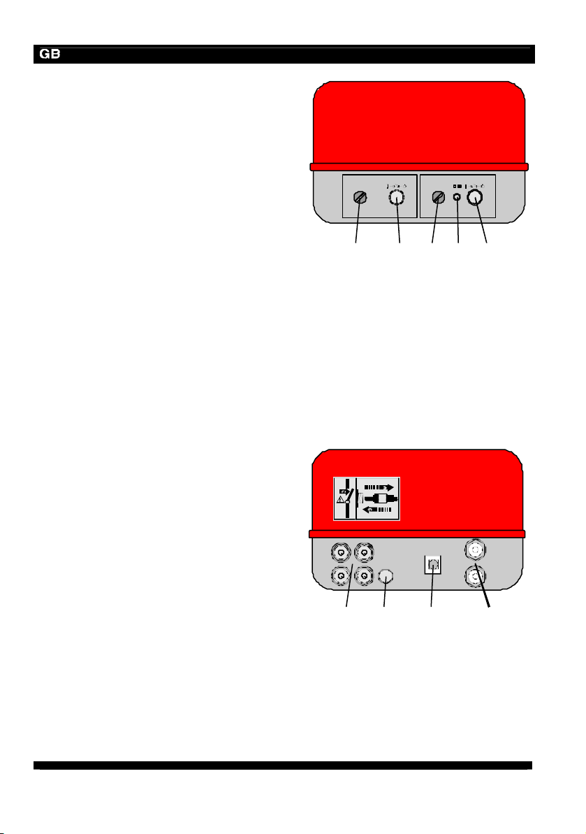
4. Make the cable connections between the charging electrodes and the high voltage
connection socket.
5. Connect the PE conductor (green-yellow) with the protective earth of the mains. Connecting
the PE conductor via parts of a machine body is insufficient.
6. Connect the charging generator to the mains.
7. Put unit into operation.
Please note in general:
Only plug in/unplug coaxial connector
when the unit is switched off!

Operating instructions AG 35
AG35 v01gb
Page 8
5Application
Preconditions:
The charging generator and the charging electrode must be connected correctly.
Protective equipment against direct contact with the charging electrode must be provided.
The unit may be put into operation by trained electricians only or by authorized persons
instructed in the potential dangers. The above mentioned persons must have read the operating
instructions and must follow the instructions, notes and safety advice.
5.1 Putting into operation
1. Turn high voltage potentiometer to the extreme left (minimum).
2. Switch on the charging and discharging units by switching the On/Off switch to On. The
green control lamp in the switch lights up.
3. Set high voltage potentiometer to desired value. The voltage measuring instrument (Fig. 2)
will indicate the voltage set.
5.2 Instructions for setting the high voltage
The output voltage depends on the current load. This is why the voltage increases if an existing
counter-electrode is covered with insulating material.
If spark-over occurs, please set a lower voltage or increase the distance between the charging
electrode and the counter-electrode or the opposing metal parts.
6Remedy of defects
Any remedy of defects must be carried out by trained electricians only. The above mentioned
persons must have read the operating instructions and must follow the instructions, notes and
safety advice.
In case of malfunctions in connection with the charging generator, first check its correct
installation and fusing (for replacement refers to Section 7.1). If this does not solve the problem,
please return the charging generator and the charging electrodes for a check-up.

Operating instructions AG 35
AG35 v01gb Page 9
7Maintenance and repairs
Danger!
High voltage!
Danger of fatal accidents!
Do not open unit!
This unit does not include any parts which can be maintained or repaired by the operator. HAUG
only is authorized to repair or calibrate the unit.
Should the unit prove defective or if a defect is suspected, switch off unit immediately and secure
against subsequent reuse.
7.1 Changing the fuse
1. Switch off unit.
2. Determine and remove the cause of the blown fuse.
3. Detach the fuse holder using a screwdriver and lift out.
4. Replace fuse and reattach fuse holder.
Use the following fuses only:
Unit type Fuse charging Fuse discharging
115 V pos./neg. 0,50 A slow; 5x20 mm 0,50 A slow; 5x20 mm
230 V pos./neg. 0,25 A slow; 5x20 mm 0,25 A slow; 5x20 mm
The unit type and the rated voltage are indicated on the nameplate.
Only use fuses of the type indicated.

Operating instructions AG 35
AG35 v01gb
Page 10
8Technical data
8.1 Characteristics and specification
Reference temperature 23 °C
Charging
High voltage terminals 2 HAUG high voltage terminals (standard)
High voltage U= approx. 40 kVDC (no load), positive or
negative
Short-circuit current Ik≤0,8 mA
Discharging
High voltage terminals 4 HAUG X-2000 terminals
High voltage U= 7 kVAC
Connected load max. 18 m (ionization device including high
voltage cable).
Short-circuit current Ik< 5 mA
8.2 Supply voltage
Type Nominal value Operating range
Frequency range Power input
AG 35 pos./neg. 115 V / 230 V ±10 %50 -60 Hz Pmax
= 100 VA

Operating instructions AG 35
AG35 v01gb Page 11
8.3 Ambient conditions
Ambient temperature:
Rated application range +5 °C to +45 °C
Extreme range for storage and transport -15 °C to +60 °C
Humidity:
Rated application range 20 % to 65 % RH
Extreme range for storage and transport 0% to 85 % RH
Air pressure:
Rated application range 800 mbar to 1060 mbar
Vibrations:
Extreme range for storage and transport max. 1,5 g (10 to 55 Hz), 1 h
Shock: max. 15 g in each direction
Recommended service position vertical, supply cable downwards
8.4 Housing
Degree of protection IP 54
Protection class I
Connection to supply voltage approx. 2,6 m fixed on unit
Dimensions:
Height approx. 348 mm
Width approx. 280 mm
Depth approx. 195 mm
Weight approx. 14 kg

D
–
0237
06.07.05
made by
HAUG GmbH & Co.KG
Friedrich-List-Straße 18
D-70771 Leinfelden-Echterdingen
Telefon 07 11 / 94 98 - 0
Telefax 07 11 / 94 98 - 298
www.haug.de
E-Mail: [email protected]
HAUG Biel AG
Postfach
CH-2500 Biel/ Bienne 6
Johann-Renfer-Strasse 60
CH-2500 Biel/ Bienne 6
Telefon 0 32 / 3 44 96 96
Telefax 0 32 / 3 44 96 97
www.haug.de
E-Mail: [email protected]
Table of contents
Other Haug Batteries Charger manuals